SkyTraq PX1120S User manual

1
SkyTraq Technology, Inc. Preliminary Draft www.skytraq.com.tw
Features
⚫230 acquisition/tracking channels
⚫Support global GPS, Beidou, Galileo, GLONASS
⚫Supports regional QZSS, SBAS
⚫16 million time-frequency hypothesis testing
per sec
⚫-148dBm cold start sensitivity
⚫-165dBm tracking sensitivity
⚫29 second cold start TTFF
⚫3.5 second TTFF with AGPS
⚫1 second hot start
⚫2.0m CEP accuracy
⚫Multipath detection and suppression
⚫Jamming detection and mitigation
⚫AGPS Support
⚫Contains LNA, SAW Filter, TCXO, RTC Xtal
⚫Works with active and passive antenna
⚫On board active antenna short protection
⚫On board active antenna detection
⚫Complete receiver in 12.2mm x 16.0mm size
⚫Operating temperature -40 ~ +85ºC
⚫Pb-free RoHS compliant
Applications
⚫Navigation and asset tracking
⚫Timing reference
L1 Quad Constellation
GNSS Receiver Module
The PX1120S is a satellite navigation receiver capable of
using GPS, Beidou, Galileo, GLONASS, QZSS, SBAS signal to
provide 3D navigation in a single compact SMD module. The
PX1120S can track all in-view GPS, Beidou, Galileo,
GLONASS, QZSS satellites. It is fully autonomous such that
once power is applied, the receiver automatically searches,
acquires and tracks satellite signals. When a sufficient
number of satellites are tracked with valid measurements,
the receiver produces 3D position and velocity outputs.
Global quad-constellation signal receiving capability enables
using greater number of satellite signal than GPS/GLONASS
dual-constellation receivers. The increased satellite number
offers superior performance in challenging urban canyon
and multipath environments.
Single-chip Phoenix positioning engine is inside the receiver
module. It features high sensitivity and fast TTFF. PX1120S
can acquire, track, and get position fix autonomously in
difficult weak signal environment. Its high sensitivity allows
continuous position coverage in nearly all outdoor
application environments. The high performance signal
parameter search engine is capable of testing 16 million
time-frequency hypotheses per second, offering superior
signal acquisition and TTFF speed.
The receiver module contains SAW filter and a notch filter
to remove out-band interference and LTE B13 signal at the
RF input prior to the first stage LNA. This configuration
allows normal operation even under strong RF interference
when cellular modem is near the PX1120S.
PX1120S is backward pin-to-pin compatible with earlier
SkyTraq 12mm x 16mm form factor GNSS module, allowing
very easy migration.

2
SkyTraq Technology, Inc. Preliminary Draft www.skytraq.com.tw
TECHNICAL SPECIFICATIONS
Receiver Type L1 frequency, 230-channel Phoenix engine
Supported Satellites GPS, Beidou, Galileo, GLONASS, QZSS
Augmentation System QZSS, WAAS, EGNOS, MSAS, GAGAN
Accuracy Position 2.0m CEP
Velocity 0.1m/sec
Time 10ns
Startup Time 1 / 28 / 29 second hot / warm / cold start under open sky average
Reacquisition 1s
Sensitivity -148dBm cold-start*1
-160dBm re-acquisition*1
-165dBm tracking*1
Multi-path Mitigation Advanced multi-path detection and suppression
A-GPS Server-based AGPS
Update Rate 1 / 2 / 4 / 5 / 8 / 10 / 20 / 25 Hz (default 1Hz)
50 / 100 Hz (PX1120S-H only)
Dynamics 4G (39.2m/sec2)
Operational Limits Altitude < 80,000m and velocity < 515m/s
Serial Interface 3.3V LVTTL level
Protocol NMEA-0183 V4.1, SkyTraq binary, 115200 baud, 8, N, 1
Datum Default WGS-84, User definable
Input Voltage 3.3V DC +/-10%
Current Consumption Acquisition 75mA @ 3.3V, Tracking 65mA @ 3.3V
Dimension 16.0mm L x 12.2mm W x 2.9mm H
Weight: 1.6g
Operating Temperature -40oC ~ +85oC
Storage Temperature -55 ~ +100oC
Humidity 5% ~ 95%
*1 : Using a good external LNA

3
SkyTraq Technology, Inc. Preliminary Draft www.skytraq.com.tw
BLOCK DIAGRAM
The PX1120S is a high performance L1 quad constellation capable satellite navigation receiver in a compact surface
mount package. It is based on the latest single-chip Phoenix GNSS receiver technology, providing high performance
signal acquisition and tracking. The simple UART serial interface and the standard NMEA-0183 protocol make usage of
PX1120S very easy and straightforward.
The PX1120S module performs all the necessary system initialization, signal acquisition, signal tracking, data
demodulation, and calculation of navigation solution autonomously.
MODELS
4
SkyTraq Technology, Inc. Preliminary Draft www.skytraq.com.tw
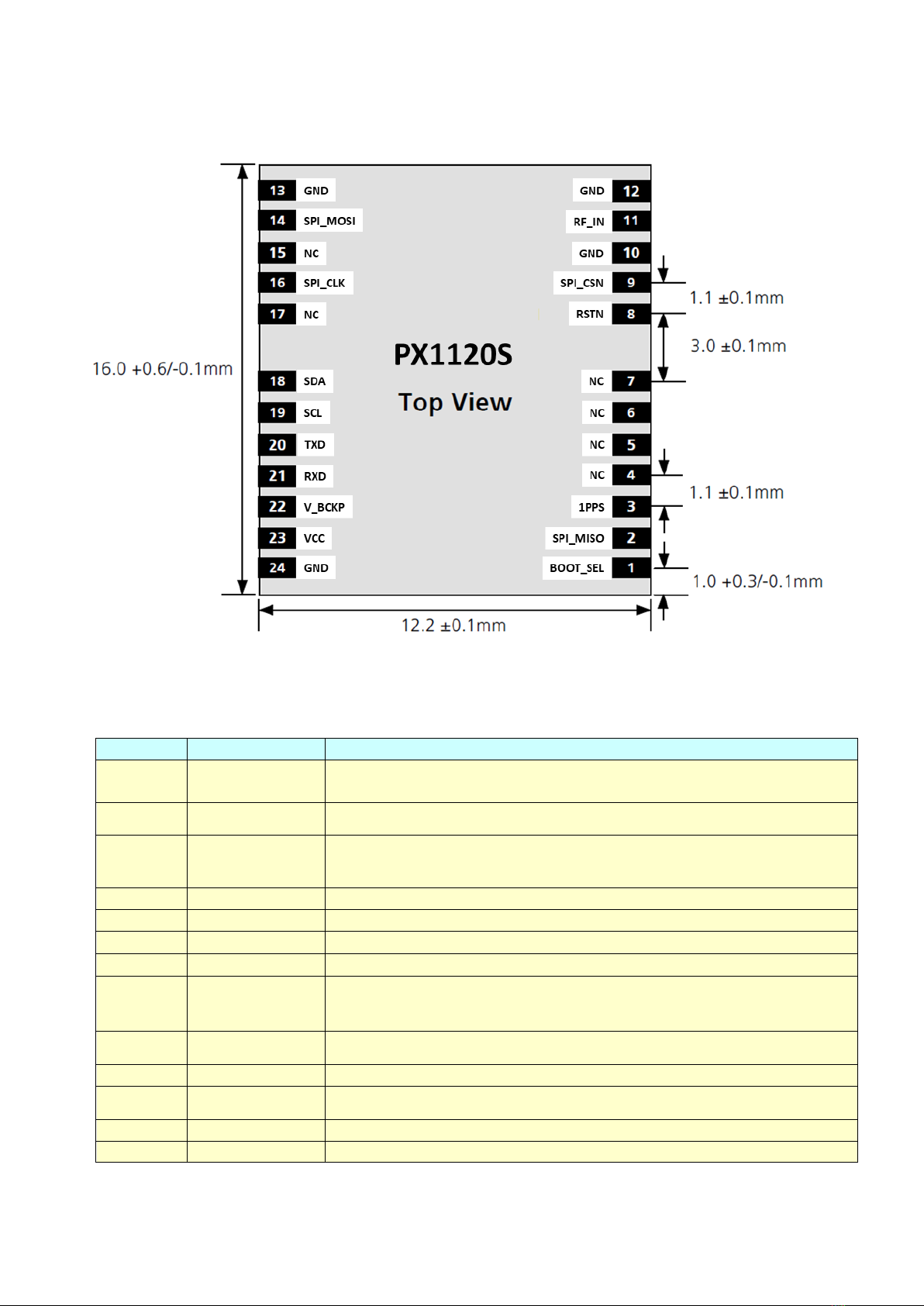
MECHANICAL CHARACTERISTICS
PINOUT DESCRIPTION
Pin No.
Name
Description
1
BOOT_SEL
No connection for normal use. Pull-low for loading firmware into empty or
corrupted Flash memory from ROM mode.
2
SPI_MISO
Not used. Leave unconnected
3
1PPS
One-pulse-per-second (1PPS) time mark output, 3.3V LVTTL. The rising edge
synchronized to UTC second when getting 3D position fix. The pulse duration is
about 100msec at rate of 1 Hz.
4
NC
No connection, empty pin
5
NC
No connection, empty pin
6
NC
No connection, empty pin
7
NC
No connection, empty pin
8
RSTN
External active-low reset input to the baseband.
Only needed when power supply rise time is very slow or software controlled
reset is desired.
9
SPI_CSN
Not used. Leave unconnected
10
GND
Ground
11
RF_IN
RF signal input, connect to L1 GNSS antenna.
3.2V active antenna bias on RF_IN.
12
GND
Ground
13
GND
Ground

5
SkyTraq Technology, Inc. Preliminary Draft www.skytraq.com.tw
14
SPI_MOSI
Not used. Leave unconnected
15
NC
No connection, empty pin
16
SPI_CLK
Not used. Leave unconnected
17
NC
No connection, empty pin
18
SDA
I2C data
19
SCL
I2C clock
20
TXD
UART serial data output, 3.3V LVTTL.
One full-duplex asynchronous serial UART port is implemented. This UART
output is normally used for sending position, time and velocity information
from the receiver in NMEA-0183 format. When idle, this pin output HIGH.
21
RXD
UART serial data input, 3.3V LVTTL.
One full-duplex asynchronous serial UART port is implemented. This UART input
is normally for sending commands or information to the receiver in SkyTraq
binary protocol. In the idle condition, this pin should be driven HIGH. If the
driving circuitry is powered independently of PX1120S, ensure that this pin is
not driven to HIGH when primary power to PX1120S is removed, or a 10K-ohm
series resistor can be added to minimize leakage current from application to
the powered off module.
22
V_BCKP
Backup supply voltage for internal RTC and backup SRAM, 1.3V ~ 3.6V. V_BCKP
must be applied whenever VCC is applied. This pin should be powered
continuously to minimize the startup time. If VCC and V_BCKP are both
removed, the receiver will be in factory default mode upon power up, all user
configuration set is lost. For applications the does not care cold starting every
time, this pin can be connect to VCC.
23
VCC
Main power supply, 3.3V +/- 10%
24
GND
Ground

6
SkyTraq Technology, Inc. Preliminary Draft www.skytraq.com.tw
ELECTRICAL SPECIFICATIONS
ABSOLUTE MAXIMUM RATINGS
Parameter
Minimum
Maximum
Condition
Supply Voltage (VCC)
-0.5
3.6
Volt
Backup Battery Voltage (V_BCKP)
-0.5
3.6
Volt
Input Pin Voltage
-0.5
VCC+0.5
Volt
Input Power at RF_IN
+5
dBm
Storage Temperature
-40
+100
degC
OPERATING CONDITIONS
Parameter
Min
Typ
Max
Unit
Supply Voltage (VCC)
3
3.3
3.6
Volt
Acquisition Current (exclude active antenna current)
75
mA
Tracking Current (exclude active antenna current)
65
mA
Backup Voltage (V_BCKP)
1.3
3.6
Volt
Backup Current (VCC voltage applied)
54
uA
Backup Current (VCC voltage off)
13
uA
Output Low Voltage
0.4
Volt
Output HIGH Voltage
2.4
Volt
Input LOW Voltage
0.8
Volt
Input HIGH Voltage
2
Volt
Input LOW Current
-10
10
uA
Input HIGH Current
-10
10
uA
RF Input Impedance (RFIN)
50
Ohm
7
SkyTraq Technology, Inc. Preliminary Draft www.skytraq.com.tw
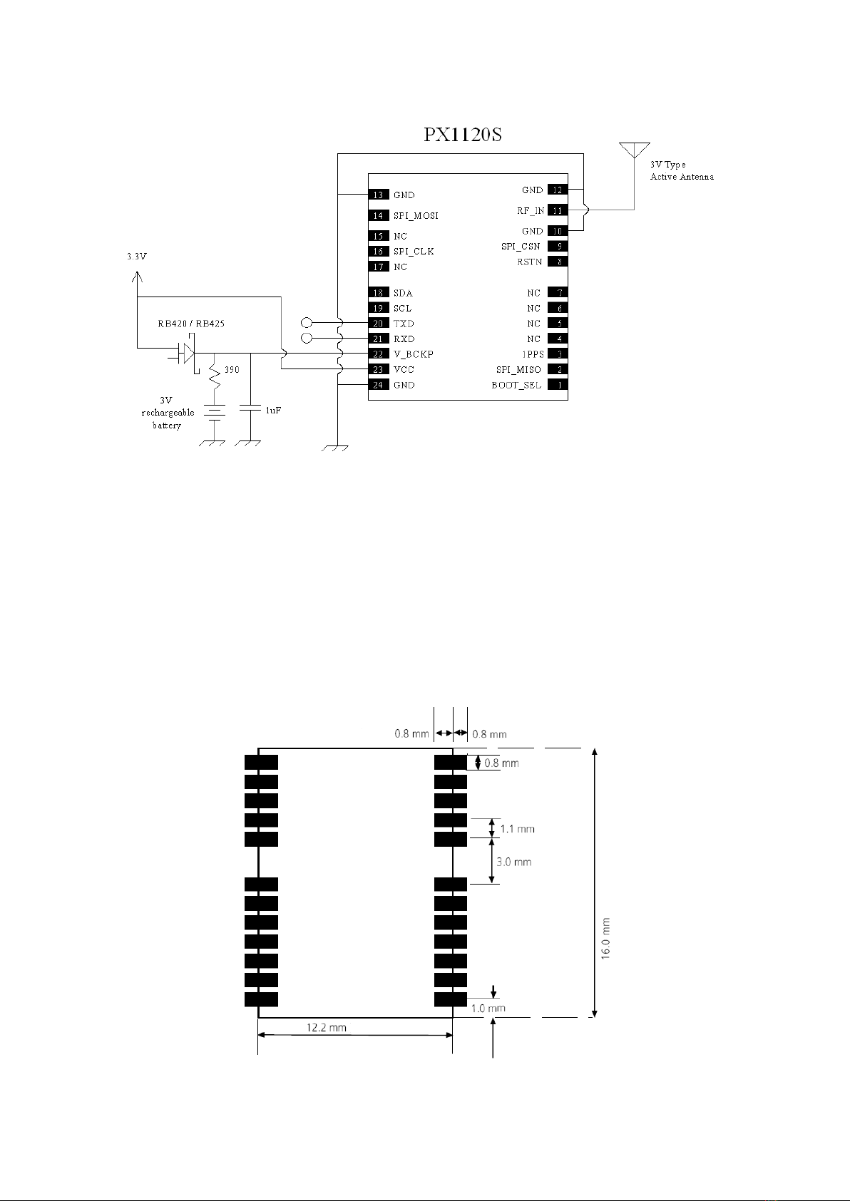
APPLICATION CIRCUIT
When PX1120S has previously been used within 2 hour, for faster time to first fix powering up without needing to
decoded ephemeris data from signal, V_BCKP should be connected to non-volatile supply; above figure with V_BCKP
connected to rechargeable battery is an example implementation. If cold starting every time powering up is not an
issue, V_BCKP can be connect to VCC.
PRECOMMENDED LAYOUT PAD
8
SkyTraq Technology, Inc. Preliminary Draft www.skytraq.com.tw
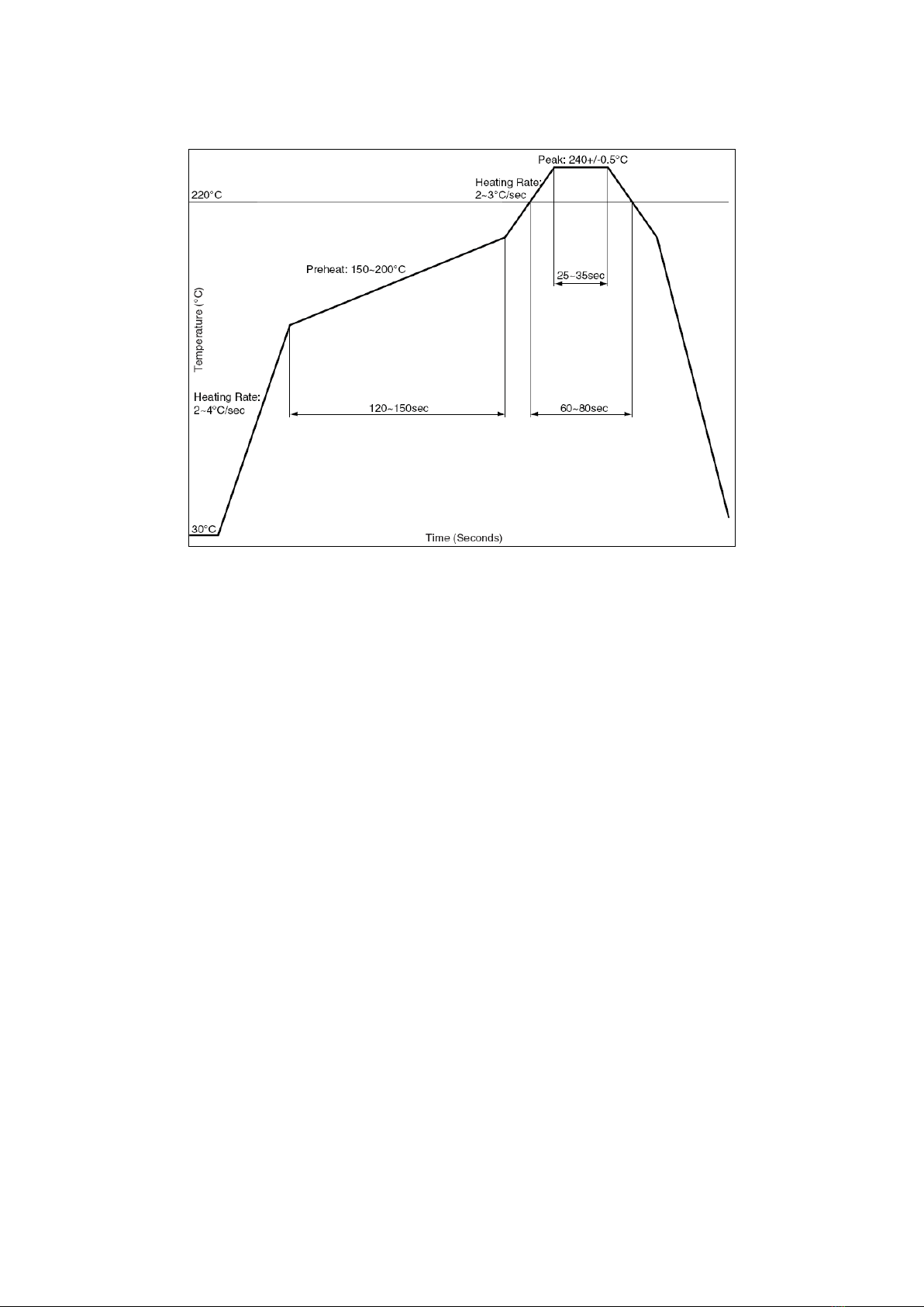
RECOMMANDED REFLOW PROFILE
The reflow profile shown above should not be exceeded, since excessive temperatures or transport times during
reflow can damage the module. Cooling temperature fall rate: max 3°C / sec
ANTENNA CONSIDERATIONS
The PX1120S can work with active antenna or passive antenna.
Passive ceramic patch antenna is low-cost and provides good sensitivity. 50-ohm output larger size ceramic patch
antenna with higher antenna gain can be connected directly to RF input of the module. Usually the ceramic patch
antenna and PX1120S are mounted on opposite side of the PCB to reduce possibility of picking up digital noise. To
improve signal reception performance, use larger ground plane under the patch antenna if possible; larger the ground
plane, larger the overall antenna gain. The center frequency of the ceramic patch antenna changes with ground plane
size. For optimal L1 quad constellation signal reception, the frequency bandwidth of the antenna needs to cover
1559MHz ~ 1605MHz when mounted on the PCB. It is usual to ask the ceramic patch antenna vendor to select or tune
a patch antenna that best matches the customer PCB.
Active antenna is essentially a passive antenna with built-in LNA and a coaxial cable to connect the antenna to the
module. It has the flexibility of being located remotely from the module, but requires antenna power. Active antenna
usually costs more than passive patch antenna, but the performance in low signal environments is usually better.
Active antenna with gain of 10 ~ 20dB and noise figure less than 1.5dB can be used with PX1120S.

9
SkyTraq Technology, Inc. Preliminary Draft www.skytraq.com.tw
Antenna Type
Passive
Active
L1 GNSS Frequency (MHz)
1558 ~ 1606
1558 ~ 1606
VSWR
< 2 (typical)
< 2 (typical)
Polarization
RHCP
RHCP
Antenna Gain
> 0dBi
> -2dBi
LNA Gain
17dB (typical)
Noise Figure
< 1.5dB
Total Gain
> 15dB
POWER SUPPLY REQUIREMENT
PX1120S requires a stable power supply, avoid ripple on VCC pin (<50mVpp). Power supply noise can affect the
receiver’s sensitivity. Bypass capacitors of 10uF and 0.1uF is recommended to be placed close to the module VCC pin;
the values could be adjusted according to the amount and type of noise present on the supply line.
BACKUP SUPPLY
The purpose of backup supply voltage pin (V_BCKP) is to keep the SRAM memory and the RTC powered when the
module is powered down. This enables the module to have a faster time-to-first-fix when the module is powered on
again. The backup current drain is less than 15μA. In normal powered on state, the internal processor access the SRAM
and current drain is higher in active mode
1PPS OUTPUT
A 1 pulse per second signal (100msec HIGH duration) is generated on 1PPS pin when the receiver has 3D position fix
using 4 or more satellites. The rising edge of the pulse is aligned with UTC second, with accuracy of about 10nsec. It
outputs constant LOW when no position fix is available initially.

10
SkyTraq Technology, Inc. Preliminary Draft www.skytraq.com.tw
LAYOUT GUIDELINES
Separate RF and digital circuits into different PCB regions.
It is necessary to maintain 50-ohm impedance throughout the entire RF signal path. Try keeping the RF signal path as
short as possible.
Do not route the RF signal line near noisy sources such as digital signals, oscillators, switching power supplies, or other
RF transmitting circuit. Do not route the RF signal under or over any other components (including PX1120S), or other
signal traces. Do not route the RF signal path on an inner layer of a multi-layer PCB to minimize signal loss.
Avoid sharp bends for RF signal path. Make two 45-deg bends or a circular bend instead of a single 90-degree bend if
needed.
Avoid vias with RF signal path whenever possible. Every via adds inductive impedance. Vias are acceptable for
connecting the RF grounds between different layers. Each of the module’s ground pins should have short trace tying
immediately to the ground plane below through a via.
The bypass capacitors should be low ESR ceramic types and located directly adjacent to the pin they are for.
HANDLING GUIDELINE
The PX1120S modules are rated MSL4, must be used for SMT reflow mounting within 72 hours after taken out from
the vacuumed ESD-protective moisture barrier bag in factory condition < 30degC / 60% RH. If this floor life time is
exceeded, or if the received ESD-protective moisture barrier bag is not in vacuumed state, then the device need to be
pre-baked before SMT reflow process. Baking is to be done at 85degC for 8 to 12 hours. Once baked, floor life counting
begins from 0, and has 72 hours of floor life at factory condition < 30degC / 60% RH. Do not bake the module in
tape-on-reel form; for baking, place parts individually onto oven tray
PX1120S module is ESD sensitive device and should be handled with care.

11
SkyTraq Technology, Inc. Preliminary Draft www.skytraq.com.tw
NMEA Output Description
The output protocol supports NMEA-0183 standard. The implemented messages include GGA, GLL, GSA, GSV, VTG,
RMC, and ZDA messages. The NMEA message output has the following sentence structure:
$aaccc,c–c*hh<CR><LF>
The detail of the sentence structure is explained in Table 1.
Table 1: The NMEA sentence structure
character
HEX
Description
“$”
24
Start of sentence.
Aaccc
Address field. “aa” is the talker identifier. “ccc” identifies the sentence type.
“,”
2C
Field delimiter.
C–c
Data sentence block.
“*”
2A
Checksum delimiter.
Hh
Checksum field.
<CR><LF>
0D0A
Ending of sentence. (carriage return, line feed)
Table 2: Overview of SkyTraq receiver’s NMEA messages
$GPGGA
Time, position, and fix related data of the GPS receiver.
$GNGLL
Position, time and fix status.
$GNGSA
Used to represent the ID’s of satellites which are used for position fix. When GPS satellites are used for
position fix, $GNGSA sentence is output with system ID 1. When GLONASS satellites are used for
position fix, $GNGSA sentence is output with system ID 2. When Galileo satellites are used for position
fix, $GNGSA sentence is output with system ID 3. When BDS satellites are used for position fix,
$GNGSA sentence is output with system ID 4.
$GPGSV
$GLGSV
$GAGSV
$GBGSV
Satellite information about elevation, azimuth and CNR, $GPGSV is used for GPS satellites, while
$GLGSV is used for GLONASS satellites, while $GAGSV is used for GALILEO satellites, while $GBGSV is
used for BEIDOU satellites.
$GNRMC
Time, date, position, course and speed data.
$GNVTG
Course and speed relative to the ground.
$GNZDA
UTC, day, month and year and time zone.

12
SkyTraq Technology, Inc. Preliminary Draft www.skytraq.com.tw
The formats of the supported NMEA messages are described as follows:
GGA –Global Positioning System Fix Data
Time, position and fix related data for a GPS receiver.
Structure:
$GPGGA,hhmmss.sss,ddmm.mmmmm,a,dddmm.mmmmm,a,x,xx,x.x,x.x,M,x.x,M,x.x,xxxx*hh<CR><LF>
1 2 3 4 5 6 7 8 9 10 11 12 13
Example:
$GNGGA,052315.000,2447.09094,N,12100.52369,E,2,12,0.6,97.9,M,19.6,M,,0000*6B<CR><LF>
Field
Name
Example
Description
1
UTC Time
025315.000
UTC of position in hhmmss.sss format, (000000.000 ~ 235959.999)
2
Latitude
2447.09094
Latitude in ddmm.mmmm mformat
Leading zeros transmitted
3
N/S Indicator
N
Latitude hemisphere indicator, ‘N’ = North, ‘S’ = South
4
Longitude
12100.52369
Longitude in dddmm.mmmmm format
Leading zeros transmitted
5
E/W Indicator
E
Longitude hemisphere indicator, ‘E’= East, ‘W’= West
6
Quality Indicator
2
GPS quality indicator
0: position fix unavailable
1: valid position fix, SPS mode
2: valid position fix, differential GPS mode
3: GPS PPS Mode, fix valid
4: Real Time Kinematic. System used in RTK mode with fixed integers
5: Float RTK. Satellite system used in RTK mode., floating integers
6: Estimated (dead reckoning) Mode
7: Manual Input Mode
8: Simulator Mode
7
Satellites Used
12
Number of satellites in use, (00 ~ 12)
8
HDOP
0.6
Horizontal dilution of precision, (0.0 ~ 99.9)
9
Altitude
97.9
mean sea level (geoid), (-9999.9 ~ 17999.9)
10
Geoidal Separation
19.6
Geoidal separation in meters
11
Age pf Differential
GPS data
Age of Differential GPS data
NULL when DGPS not used
12
DGPS Station ID
0000
Differential reference station ID, 0000 ~ 1023
13
Checksum
6B

13
SkyTraq Technology, Inc. Preliminary Draft www.skytraq.com.tw
GLL –Latitude/Longitude
Latitude and longitude of current position, time, and status.
Structure:
$GNGLL,ddmm.mmmmm,a,dddmm.mmmmm,a,hhmmss.sss,A,a*hh<CR><LF>
1 2 3 4 5 6 7 8
Example:
$GNGLL,2447.09094,N, 12100.52369,E, 052315.000,A,D*4A<CR><LF>
Field
Name
Example
Description
1
Latitude
2447.09094
Latitude in ddmm.mmmmm format
Leading zeros transmitted
2
N/S Indicator
N
Latitude hemisphere indicator
‘N’ = North
‘S’ = South
3
Longitude
12100.52369
Longitude in dddmm.mmmmm format
Leading zeros transmitted
4
E/W Indicator
E
Longitude hemisphere indicator
‘E’= East
‘W’= West
5
UTC Time
052315.000
UTC time in hhmmss.sss format (000000.000 ~ 235959.999)
6
Status
A
Status, ‘A’ = Data valid, ‘V’ = Data not valid
7
Mode Indicator
D
Mode indicator
‘A’ = Autonomous mode
‘D’ = Differential mode
‘E’ = Estimated (dead reckoning) mode
‘M’ = Manual input mode
‘S’ = Simulator mode
‘N’ = Data not valid
8
Checksum
4A

14
SkyTraq Technology, Inc. Preliminary Draft www.skytraq.com.tw
GSA –GNSS DOP and Active Satellites
GNSS receiver operating mode, satellites used in the navigation solution reported by the GGA or GNS sentence and
DOP values.
Structure:
$GNGSA,A,x,xx,xx,xx,xx,xx,xx,xx,xx,xx,xx,xx,xx,x.x,x.x,x.x,x*hh<CR><LF>
1 2 3 3 3 3 3 3 3 3 3 3 3 3 4 5 6 7 8
Example:
$GNGSA,A,3,10,12,14,20,21,24,25,31,32,193,,,1.1,0.6,0.9,1*01<CR><LF>
$GNGSA,A,3,69,70,73,79,80,,,,,,,,1.1,0.6,0.9,2*3C<CR><LF>
$GNGSA,A,3,01,02,03,06,09,10,14,16,21,22,26,,1.1,0.6,0.9,4<CR><LF>
Field
Name
Example
Description
1
Mode
A
Mode
‘M’ = Manual, forced to operate in 2D or 3D mode
‘A’ = Automatic, allowed to automatically switch 2D/3D
2
Mode
3
Fix type
1 = Fix not available
2 = 2D
3 = 3D
3
Satellite used 1~12
10, 12, 14, 20,
21, 24, 25, 31,
32, 193
01 ~ 32 are for GPS; 33 ~ 64 are for WAAS (PRN minus 87); 193
~ 197 are for QZSS; 65 ~ 88 are for GLONASS (GL PRN) ; 01 ~ 36
are for GALILEO (GA PRN); 01 ~ 37 are for BDS (BD PRN). GPS,
GLONASS, GALILEO and BDS satellites are differentiated by the
GNSS system ID in table 3. Maximally 12 satellites are included
in each GSA sentence.
4
PDOP
1.1
Position dilution of precision (0.0 to 99.9)
5
HDOP
0.6
Horizontal dilution of precision (0.0 to 99.9)
6
VDOP
0.9
Vertical dilution of precision (0.0 to 99.9)
7
GNSS System ID
1
GNSS system ID*
1 = GPS
2 = GLONASS
3 = GALILEO
4 = BDS
5 = IRNSS
8
Checksum
01
*GNSS System ID identifies the GNSS system ID according to Table 3.

15
SkyTraq Technology, Inc. Preliminary Draft www.skytraq.com.tw
Table 3: GNSS Identification Table for GSA, GSV
System
System ID (Talker)
Signal ID
Signal Name
GPS
1 (GP)
0
1
2
3
4
5
6
7
8
All signals
L1 C/A
L1 P(Y)
L1C
L2 P(Y)
L2C-M
L2C-L
L5-I
L5-Q
GLONASS
2 (GL)
0
1
2
3
4
All signals
G1 C/A
G1P
G2 C/A
GLONASS (M) G2P
GALILEO
3 (GA)
0
1
2
3
4
5
6
7
All signals
E5a
E5b
E5 a+b
E6-A
E6-BC
L1-A
L1-BC
BDS
4 (BD)
0
1
2
3
4
5
All signals
B1
B2A
B2
B3
B1C
IRNSS
5 (GI)
0
4
All signals
L5

16
SkyTraq Technology, Inc. Preliminary Draft www.skytraq.com.tw
GSV –GNSS Satellites in View
Number of satellites (SV) in view, satellite ID numbers, elevation, azimuth, and SNR value. Four satellites maximum per
transmission.
Structure:
$GPGSV,x,x,xx,xx,xx,xxx,xx,…,xx,xx,xxx,xx,x *hh<CR><LF>
1 2 3 4 5 6 7 4 5 6 7 8 9
Example:
$GPGSV,4,1,15,10,79,250,50,194,73,072,,193,69,127,45,25,64,114,46,1*67<CR><LF>
$GPGSV,4,2,15,20,54,175,45,32,44,334,46,41,39,242,43,12,36,055,46,1*68<CR><LF>
$GPGSV,4,3,15,31,32,256,45,14,25,310,39,24,15,049,38,21,07,191,35,1*61<CR><LF>
$GPGSV,4,4,15,15,04,106,18,29,03,144,,26,01,206,,1*56<CR><LF>
$GLGSV,2,1,06,80,77,332,44,69,55,098,49,70,46,347,43,73,29,221,45,1*79<CR><LF>
$GLGSV,2,2,06,79,25,026,42,71,01,325,,1*76<CR><LF>
$GBGSV,3,1,12,21,77,107,50,26,73,278,49,06,59,009,45,03,58,203,43,1*7D<CR><LF>
$GBGSV,3,2,12,16,58,002,47,07,55,180,,01,53,142,43,09,47,329,43,1*73<CR><LF>
$GBGSV,3,3,12,02,40,241,39,10,31,200,40,22,25,134,41,14,19,321,41,1*77<CR><LF>
Field
Name
Example
Description
1
Number of message
4
Total number of GSV messages to be transmitted (1-5)
2
Sequence number
1
Sequence number of current GSV message
3
Satellites in view
15
Total number of satellites in view (00 ~ 20)
4
Satellite ID
10
01 ~ 32 are for GPS; 33 ~ 64 are for WAAS (PRN minus 87); 193
~ 197 are for QZSS; 65 ~ 88 are for GLONASS (GL PRN) ; 01 ~ 36
are for GALILEO (GA PRN); 01 ~ 37 are for BDS (BD PRN). GPS,
GLONASS, GALILEO and BDS satellites are differentiated by the
GNSS system ID in table 3. Maximally 4 satellites are included in
each GSV sentence.
5
Elevation
79
Satellite elevation in degrees, (00 ~ 90)
6
Azimuth
250
Satellite azimuth angle in degrees, (000 ~ 359 )
7
SNR
50
C/No in dB (00 ~ 99)
Null when not tracking
8
GNSS System ID
1
Signal ID*
9
Checksum
67
*GNSS Signal ID identifies the GNSS signal name according to Table 3.

17
SkyTraq Technology, Inc. Preliminary Draft www.skytraq.com.tw
RMC –Recommended Minimum Specific GNSS Data
Time, date, position, course and speed data provided by a GNSS navigation receiver.
Structure:
$GNRMC,hhmmss.sss,A,dddmm.mmmmm,a,dddmm.mmmmm,a,x.x,x.x,ddmmyy,,,a,a*hh<CR><LF>
1 2 3 4 5 6 7 8 9 101112
Example:
$GNRMC,052315.000,A,2447.09094,N,12100.52369,E,000.0,169.9,261219,,,D,V*0F<CR><LF>
Field
Name
Example
Description
1
UTC time
052315.000
UTC time in hhmmss.sss format (000000.00 ~ 235959.999)
2
Status
A
Status
‘V’ = Navigation receiver warning
‘A’ = Data Valid
3
Latitude
2447.09094
Latitude in dddmm.mmmmm format
Leading zeros transmitted
4
N/S indicator
N
Latitude hemisphere indicator
‘N’ = North
‘S’ = South
5
Longitude
12100.52369
Longitude in dddmm.mmmmm format
Leading zeros transmitted
6
E/W Indicator
E
Longitude hemisphere indicator
‘E’= East
‘W’= West
7
Speed over ground
000.0
Speed over ground in knots (000.0 ~ 999.9)
8
Course over ground
169.9
Course over ground in degrees (000.0 ~ 359.9)
9
UTC Date
261219
UTC date of position fix, ddmmyy format
10
Mode indicator
D
Mode indicator
‘A’ = Autonomous mode
‘D’ = Differential mode
‘E’ = Estimated (dead reckoning) mode
‘F’ = Float RTK. Satellite system used in RTK mode, floating
integers
‘M’= Manual Input Mode
‘N’ = Data not valid
‘P’= Precise
‘R’ = Real Time Kinematic. System used in RTK mode with fixed
integers
‘S’= Simulator Mode
11
Navigation status
Navigation status indicator according to IEC61108 requirement
on ‘Navigational (or Failure) warnings and status indicators’.
‘S’= Safe
‘C’= Caution
‘U’= Unsafe
‘V’= Navigation status not valid, equipment is not providing
navigation status indicator.
12
checksum
0F

18
SkyTraq Technology, Inc. Preliminary Draft www.skytraq.com.tw
VTG –Course Over Ground and Ground Speed
The actual course and speed relative to the ground.
Structure:
GNVTG,x.x,T,,M,x.x,N,x.x,K,a*hh<CR><LF>
1 2 3 4 5
Example:
$GNVTG,169.9,T,,M,000.0,N,000.0,K,D*11<CR><LF>
Field
Name
Example
Description
1
Course
169.9
True course over ground in degrees (000.0 ~ 359.9)
2
Speed
000.0
Speed over ground in knots (000.0 ~ 999.9)
3
Speed
000.0
Speed over ground in kilometers per hour (000.0 ~ 1800.0)
4
Mode
D
Mode indicator
‘A’ = Autonomous mode
‘D’ = Differential mode
‘E’ = Estimated (dead reckoning) mode
‘M’= Manual input mode
‘N’ = Data not valid
‘P’= Precise
‘S’= Simulator mode
5
Checksum
11
ZDA –TIME AND DATE
UTC, day, month, year and local time zone
Structure:
$GNZDA,hhmmss.sss,xx,xx,xxxx,xx,xx*hh<CR><LF>
1 2 3 4 5 6 7
Example:
$GNZDA,052315.000,26,12,2019,00,00*45<CR><LF>
Field
Name
Example
Units
Description
1
UTC time
052315.000
UTC time in hhmmss.sss format (000000.00 ~ 235959.999)
2
UTC Day
26
UTC time: day (01 ~ 31)
3
UTC Month
12
UTC time: month (01 ~ 12)
4
UTC Year
209
UTC time: year (4 digit format)
5
Local zone hour
00
Local zone hours (00 ~ +/- 13)
6
Local zone minutes
00
Local zone minutes (00 ~59)
7
Checksum
45
Checksum

19
SkyTraq Technology, Inc. Preliminary Draft www.skytraq.com.tw
ORDERING INFORMATION
Model Name
Description
PX1120S
L1 Quad GNSS Receiver Module
PX1125S-01B
Crystal Oscillator + Temperature Sensor Version of PX1120S Supporting GPS / GLONASS /
Galileo for TCXO Shortage Period.
PX1120S-G
GPS-only version, NMEA 3.1 Output Compatible with S1216F8
PX1120S-GG
GPS/GLONASS version, NMEA 3.1 Output Compatible with S1216F8-GL
PX1120S-GG12
GPS/GLONASS version, NMEA 3.1 Output Compatible with S1216F8-GL12
PX1120S-GB
GPS/Beidou version, NMEA 3.1 Output Compatible with S1216F8-BD
PX1120S-3G
GPS/GLONASS/Galileo version, NMEA 3.1 Output
PX1120S-GGB
GPS/GLONASS/Beidou version, NMEA 3.1 Output
PX1120S-H
Supporting additional GPS/GLONASS 50Hz and GPS 100Hz update rates

20
SkyTraq Technology, Inc. Preliminary Draft www.skytraq.com.tw
Revision History
Revision
Date
Description
1
December 27, 2019
Initial release
2
April 17, 2020
Updated page-2 footnote
3
September 1, 2020
Removed page-2 footnote
4
January 29, 2021
Updated ordering information
5
May 4, 2021
Updated current consumption
6
August 4, 2021
Added PX1120S-H and models description
7
October 14, 2021
Updated ordering information
8
November 1, 2021
Updated ordering information
9
March 2, 2022
Updated position accuracy number
The information provided is believed to be accurate and reliable. These materials are provided to customers and may be used for informational
purposes only. No responsibility is assumed for errors or omissions in these materials, or for its use. Changes to specification can occur at any time
without notice.
These materials are provides “as is” without warranty of any kind, either expressed or implied, relating to sale and/or use including liability or
warranties relating to fitness for a particular purpose, consequential or incidental damages, merchantability, or infringement of any patent,
copyright or other intellectual property right. No warrant on the accuracy or completeness of the information, text, graphics or other items
contained within these materials. No liability assumed for any special, indirect, incidental, or consequential damages, including without limitation,
lost revenues or lost profits, which may result from the use of these materials.
The product is not intended for use in medical, life-support devices, or applications involving potential risk of death, personal injury, or severe
property damage in case of failure of the product.
This manual suits for next models
5
Table of contents
Other SkyTraq Receiver manuals


