INIM Electronics SmartLink-G Owner's manual

SmartLink-G, SmartLink-GP
GSM Dialler
Programming
Manual
PATENT PENDING
0470

Programming manual
2
Copyright
The information contained in this document is the sole
property of INIM Electronics s.r.l. No part may be copied
without written authorization from INIM Electronics s.r.l.
All rights reserved.
Directive 1999/5/CE (R&TTE) compliance.
Hereby INIM Electronics s.r.l. declares that the
SmartLink-G and SmartLink-GP are in compliance with
the essential requirements and other relevant provisions
of Directive 1999/5/CE.
The full declarations of conformity of the above-
mentioned devices are available at URL:
www.inim.biz/dc.html.

3
Programming manual
Table of contents
Chapter 1 Overview ..................................... 5
Chapter 2 General information....................... 6
2.1 In-box documentation 6
2.2 Manual details 6
2.3 Addressees 6
2.4 Software information 6
2.5 Intellectual property rights 6
2.6 Key 6
Chapter 3 Programming the SmartLink-GP ......8
3.1 Introduction 8
3.2 Installing the SmartLeague software 8
3.3 SmartLeague software 9
3.4 Recommended programming flow 12
3.5 Settting up contact data 13
3.6 Setting up the SmartLink parameters 18
3.7 Programming the Inputs and Outputs —
IN&OUT 24
3.8 Programming the SmartLink-GP as an
Intrusion control panel 29
3.9 Associating incoming and outgoing calls with
actions 31
3.10 Programming event generated actions 34
3.11 Programming periodic events 43
3.12 Remote control of the SmartLink-GP via SMS
text messages 44
3.13 Programming the device via SMS messages
47
3.14 Remote control of SmartLink-GP via DTMF
tones 52
Appendix A Example wiring diagram intrusion con-
trol ........................................... 57
Appendix B Features not managed by the Smart-
Link-G model.............................. 59

4
Programming manual
Appendix C Default settings of the Smartlink-GP60
Appendix D Inhibit events for output control ....61
• Notes.........................................62

Overview 5
Programming manual
Chapter 1
Overview
The SmartLink is available in the following models:
• SmartLink-GP
•SmartLink-G
Besides the features of the SmartLink-G model, the SmartLink-GP model
also provides the following advanced features:
1. Intrusion control panel facility
2. Voice dialler (requires SmartLogos60 accessory board)
3. PSTN line call management
The Smartlink-G model does not provide these features.
This manual describes the Smartlink-GP features and programming process.
SmartLink-G users can skip the sections which refer to the advanced
features.
Refer to Appendix B for a detailed list of the Smartlink-GP advanced features
and flexibility-optimized software.

6 General information
Programming manual
Chapter 2
General information
2.1 In-box documentation
• Installation manual
• Programming manual (this manual)
The Installation manual is inside the device package. For extra copies of the
installation manual, please contact INIM electronics specifying the order code
shown in the Installation manual Appendix B.
2.2 Manual details
Title: SmartLink-G and SmartLink-GP Programming Manual
• Edition,Version: 2.10
• Month and Year of issue: October 2012
• Code: DCMPINE0SLINK
2.3 Addressees
• Installer
• Technical assistance
2.4 Software information
• Smartleague software version: 3.x.x
• Firmware version : 2.x.x
2.5 Intellectual property rights
The information contained in this document is private property. All rights
reserved.
No part of this document may be copied or reproduced unless expressly
authorized in writing by INIM Electronics, in particular the parts regarding
the device specified in the Installation Manual paragraph 2.8 Device identifier
INIM Electronics s.r.l. shall not be responsible for damage arising from
improper application or use.
2.6 Key
2.6.1 Glossary and terminology
Device: refers to the device specified in the Installation Manual paragraph
2.8 Device identifier.

General information 7
Programming manual
Left, right, behind, above, below: indications using the operator's
position in front of the mounted device as the reference point.
Pulse output: same as "monostable output"
Dialler (phone, SMS, digital):same as "communicator"
Qualified personnel: those persons whose training, expertise and
knowledge of the respective laws and bylaws regarding service conditions
and the prevention of accidents, are able to identify and avoid all possible
situations of danger.
Click on: click to select a specific item (from drop-down menu, options box,
graphic object, etc.).
Select: click on a video button.
2.6.2 Graphic key
Text in italics: indicates the title of a chapter, section, paragraph, table or
figure in this manual or other published reference.
<text>: editable space, for example #<CustomerCode># may become
#0001#.
[Uppercase letters] (e.g..[A]): indicate the device parts or video objects.
Note: The detached notes contain important information about
the respective text.
Attention: The attention prompts indicate that total or partial
disregard of the procedure could damage the
connected devices.
Danger: The danger warnings indicate that total or partial
disregard of the procedure could injure the operator
or persons in the vicinity.

8 Programming the SmartLink-GP
Programming manual
Chapter 3
Programming the SmartLink-GP
3.1 Introduction
The SmartLink-GP can be programmed to manage:
• Intrusion control
• SMS dialler
• Contact ID Dialler
• Remote appliance control
• Voice dialler (optional feature)
Note: If the SmartLink-GP is used as a reserve line generator, no
programming is required.
SmartLink-GP programming requirements:
• a portable computer for parameter downloading to the powered-up wall-
mounted device
• RS232 link cable
• SmartLeague software
3.2 Installing the SmartLeague software
3.2.1 Installing SmartLeague from the CD
If included in your purchase order, you will have the SmartLeague
Installation CD containing the software for the respective SmartLink-GP
firmware. Check the software version, refer to Help, About SmartLeague.
New versions of the SmartLeague software can be downloaded from the INIM
electronics Web address at www.inim.biz.
After installing the SmartLeague software, contact the Web address to find
out about new versions. Internet connection required.
Installation instructions
1. Insert the Installation CD into your service computer.
2. Select 'Computer Resources' on your desktop.
3. Find the CD unit, double click on the icon: the CD contents will be
displayed.
4. Double click on Setup.exe: the Welcome to the installation
program window appears.
5. Select 'Continue': the Folder selection window appears.

Programming the SmartLink-GP 9
Programming manual
Note: You should select the suggested folder.
6. Select 'Continue': file installation initializes, the progress bar will
indicate completion.
Note: Always complete installation, do not select Cancel during
the installation phase.
7. Once installation has been completed, the SmartLeague icon will appear
on your desktop (if requested by the user) and in the program
list:
3.2.2 Check for the availability of a new version
of the SmartLeague software.
8. Connect with us at www.inim.biz to find out about SmartLeague
software upgrades.
9. View the differences between the new version and the installed version.
10. Work carefully through the upgrade instructions.
3.2.3 Check for the availability of a new version
of the firmware.
11. Connect with us at www.inim.biz to find out about SmartLink-GP
firmware upgrades.
12. Work carefully through the download and installation instructions. All
upgrades come with the revised version of the manual.
3.3 SmartLeague software
SmartLeague is the SmartLink-GP configuring software. The program is
designed to run on your service computer and will allow you to program
most of the SmartLink-GP parameters without actually being connected to
the system.
Your service computer must be connected to the mounted powered-up
SmartLink-GP during the parameter downloading phase.
The connection cable must be long enough to reach the mounted device
without difficulty. Refer to the Installation Manual - paragraph 7.13
Connecting the RS232 PC serial link.
The parameter settings can be saved to the SmartLeague database and used
for service purposes or as a 'standard configuration' for other SmartLink-GP
devices.
During service sessions, you will be able to view and change the SmartLink-
GP parameter settings.
10 Programming the SmartLink-GP
Programming manual
3.3.1 General information
SmartLeague is the configuring software of the entire INIM electronics
product spectrum. You can configure numerous devices/systems on your
office service computer, regardless of the type of device/system.
You can configure a device on your service computer, then write the data to
the device EEPROM when you get to the customer's premises.
You can work on several parameter groups ('solutions') at the same time, for
example, you can copy a device/system configuration and download it to
another device/system of the same type. Each solution has its own
configuration file:
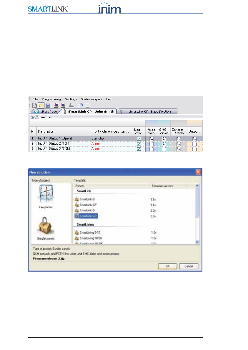
If you wish to create a 'solution', you must first select the device type and
model:
The start page of the SmartLeague software is connected to the INIM Web
providers, if you are connected to internet, it will show all the updated
information regarding software and firmware upgrades, revised manuals,
instruction inserts and newsletters, etc.

Programming the SmartLink-GP 11
Programming manual
Note: To change the Web address of the page and reconnection
interval, select Settings, Application data,
Miscellaneous .
3.3.2 Setting up the computer serial output
Using the Settings, Application data, Serial Ports menus, check that the
selected settings match the serial cable you intend using for the computer to
SmartLink-GP connection.
3.3.3 Configuring a new system
1. Create a new solution (select File, New), or open a solution previously
used for a similar system (select File, Open), and save it in the name of
the new customer with the new account code.
2. Customize the parameter settings.
3. Save (select File, Save) and if necessary, print the details (menu File,
Print).
4. Connect the computer to the RS232 serial port of the device.
5. Download the 'solution' (configuration) to the device, select Program,
Download): all six LEDs will blink during this phase.
Note: If an error occurs during the downloading phase, you must
repeat the operation. The new data will overwrite the
previous configuration.
3.3.4 Programming an installed device
1. Connect the computer to the RS232 serial port of the device.
2. Create a new solution (select File, New), or open the current solution
(configuration) of the system (select File, Open).
3. To load the current parameters, select Program, Upload: all six LEDs
will blink during this phase.
4. Customize the parameter settings.
5. Save (select File, Save) and if necessary, print the details (menu File,
Print).
Download the 'solution' (configuration) to the device, select Program,
Download: all six LEDs will blink during this phase.
Note: If an error occurs during the downloading phase, you will
have to repeat the operation. The new data will overwrite
the previous configuration.

12 Programming the SmartLink-GP
Programming manual
3.3.5 Status enquiry
1. Connect the computer to the RS232 serial port of the device.
2. Select Control panel, Status enquiry: a window appears showing the
IMEI code, SIM data, installed version and battery, GSM network and
input statuses.
3. Select Send SMS, to send an SMS Test text from the SmartLink.
3.3.6 Viewing the Events log
1. Connect the computer to the RS232 serial port of the device.
2. Create a new solution (select File, New), or open the current solution
(configuration) of the system (select File, Open).
3. To view the contents of the events log, select Log.
4. Select the icon. The recorded events will appear on the bottom left.
5. The recorded events appear.
Note: The contents of the event log can be printed or saved to the
database.
3.3.7 Print
1. Define the printout header (e.g. Logo, Company name, etc.).
2. To type in the respective data, select Printer settings, from Settings,
Application settings.
3. Select the icon and click on the file you wish to print.
3.4 Recommended programming flow
Due to the flexibility-optimized SmartLink-GP software, many ways of
preparing the parameters exist, depending on the type of application.
Generally, you can proceed as follows.
1. Prepare the data:
• phone numbers for Contact ID reports, SMS texts and voice messages
• SMS text messages
• voice messages
• Caller ID codes
2. Configure the device parameters
3. Configure the inputs and outputs (for intrusion control and reserve line
applications).
4. Associate the incoming/outgoing calls with specific actions.
5. Program the events which will:
• Send pre-set SMS text messages
• Send Contact ID reports
• Send voice messages
Programming the SmartLink-GP 13
Programming manual
• Activate/Deactivate outputs
• Generate constraint
6. Program periodic events
3.5 Settting up contact data
3.5.1 Settting up outgoing call numbers
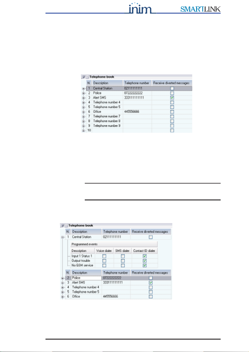
Figure 1 - Phonebook
The SmartLink-GP sends outgoing Contact ID reports, voice message calls
and event-generated SMS text messages (direct or diverted) to the 10 phone
numbers in the phonebook.
For example, Central station numbers for Contact ID reports or the phone
numbers for SMS text messages.
Note: International numbers must be entered in the following
format: +xxyyyyyyyyy (e.g. “+390611111”).
To view events which generate outgoing calls to the phone number
concerned, select ‘+’ next to the progressive number:
14 Programming the SmartLink-GP
Programming manual
3.5.2 Setting up the SMS dialler messages
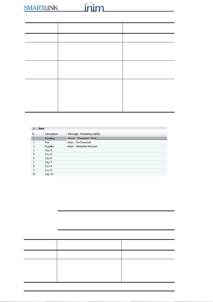
Figure 2 - SMS table
The SmartLink-GP manages 10 SMS text messages to communicate
recognized events (trouble, input status change, periodic events, etc.) to the
numbers in the Phonebook. For example, you can pre-set an SMS text
message to warn users of 'flood below deck or basement flood'.
Note: When programming the SMS dialler, you must at least
define the SMS text message description, the text can
be entered successively.
Parameter Description Note
No. Phone number slot
Description Description which identifies
the event-associated phone
number.
Phone
number
number including national
and, if necessary,
international phone code.
Diverted
messages
Diverts SMS text messages
from enabled phone numbers
to the phone number (Divert
SMS option from the Phone
number functions table).
For example, this
option will allow you to
view which SMS text
messages SmartLink-
GP receives from the
numbers concerned.
Parameter Description Note
No. SMS text message slot
Description The description which
identifies the event-
associated SMS text
message.

Programming the SmartLink-GP 15
Programming manual
3.5.3 Setting up the voice dialler messages
(requires SmartLogos60 voice board)
Figure 3 - Voice Message table
SmartLink-GP manages eight voice messages to communicate recognized
events (trouble, input status change, periodic events, etc.) to the numbers in
the Phonebook.
Note:
More than one voice message can be included in a single
call. This option optimizes the voice message feature. You
can create a group of event messages and a group of
messages associated with the places the events may occur.
For example, as illustrated, you can select Msg4=“Attempted Tamper” and
Msg6=“Jenner St offices" for one call and Msg3=“Attempted Intrusion” and
Msg6=“Jenner St offices” for another call.
Note: The SmartLink will start the voice message as soon as the
recipient answers the call.
Message Message text The underline in the
message box indicates
the maximum length of
the message. 80
characters for
messages 1 to 5; 40
characters for
messages 6 to 10.
Parameter Description Note
No. Voice message slot assigned during the
recording phase.
Description Description which identifies the event generated
voice message.
Parameter Description Note

16 Programming the SmartLink-GP
Programming manual
Recording voice messages
You can record the voice messages by connecting an ordinary touch-tone
phone to connector J6 on SmartLogos60 board. Refer to the Installation
Manual - paragraph 7.9 Connecting the SmartLogos60 (accessory item).
The recording procedure is as follows:

Programming the SmartLink-GP 17
Programming manual
3.5.4 Setting up Caller ID codes
Figure 4 - Codes table
The SmartLeague application uses the installer, user and customer ID codes
for SMS or DTMF caller identification (Caller ID) and for SmartLink-GP
identification during Contact ID report transmissions to central stations.
Parameter Description Note
Installer code This is the access code
that SmartLeague uses
during communications
with the SmartLink-GP.
User code This is the access code
the user must enter in
SMS text message or
DTMF commands to the
SmartLink-GP.
See paragraph 3.12
Remote control of the
SmartLink-GP via SMS text
messages and paragraph
3.14 Remote control of
SmartLink-GP via DTMF
tones.
Customer
code
This is the code which
identifies the SmartLink-
GP during Contact ID
report transmissions to
central stations.

18 Programming the SmartLink-GP
Programming manual
3.6 Setting up the SmartLink parameters
This table contains the general parameters of the SmartLink-GP.
Group
Parameter Description Note
Intrusion control parameters
Enable
intrusion
protection
parameters
If selected,
the SmartLink-GP will
operate as an intrusion
control panel. The inputs and
outputs and associated
events will be used for
intrusion control
management.
Delay
(input/output)
If the SmartLink-GP intrusion
control panel is disarmed,
the is the interval between
the moment of arming and
the instant the device detects
alarm status on an input.
If the intrusion control panel
is armed, it is the time the
user has to disarm the
SmartLink-GP after violating
a delayed input. If the user
does not disarm the intrusion
control panel before the
delay ends
the SmartLink-GP will
generate an alarm event.
See paragraph 3.7
Programming the
Inputs and Outputs —
IN&OUT, section
Inputs, Parameter
Type.
PSTN (land line) parameters
Tone check If selected, the device will
check the line for the dialing
tone before dialing.
Pulse dialing If selected, the device will
use pulse dialing, otherwise
it will use DTMF dialing.

Programming the SmartLink-GP 19
Programming manual
Trouble warning parameters
Enable 'PSTN
(land line)
down' warning
If selected, it will enable the
Land line down event and
visual signaling on the
trouble LED.
Enable 'No
GSM Service'
warning
If selected, it will enable the
No GSM Service event and
visual signaling on the
trouble LED.
Answerphone parameters
Enable land
line (PSTN)
answerphone
If selected, it will enable
remote control of the device
via DTMF tones on the land
line (PSTN).
If SmartLink-GP is
connected to a fax
machine or modem,
you must also enable
the Double call
option.
Enable GSM
answerphone
If selected, it will enable
remote control of the device
via DTMF tones on the GSM
network.
Enable Double
Call
Useful if the SmartLink-GP is
connected to a fax machine
or modem that will answer
after a set Number of
rings.
To stop a fax machine or
modem from answering a
DTMF maintenance call, first
enable the Double call option
then call the panel and hang
up (the call rings must be
less than the set Number of
rings), make a second call
within 60 seconds of hanging
up. The SmartLink-GP will
pick up the call on the first
ring of the second call and
will be ready to accept DTMF
commands.
Only if Enable PSTN
answerphone option
has been selected.
Program the fax
machine or modem to
answer after the set
Number of rings.
Number of
rings
The number of rings which
must be detected before
answering an incoming call.
Group
Parameter Description Note

20 Programming the SmartLink-GP
Programming manual
Dialler parameters
Call all
Contact ID
numbers
If selected, the device will
call alternately the two or
more numbers associated
with an event (to transmit
Contact ID reports) until all
numbers successfully receive
the communication. If not
selected, the device will call
until one number only
successfully receives the
communication.
Call all voice
numbers
Same as Call all Contact ID
numbers, for voice message
calls.
Confirm with * If enabled, the SmartLink will
consider the voice call
successful when the recipient
presses “*” on the telephone
keypad.
Bypass voice
check
If enabled, the SmartLink will
start the voice message 5
seconds after dialing the
respective contact number.
Call attempts The maximum number of call
attempts the SmartLink-GP
will make when operating as
a dialer. If a call is
unsuccessful (i.e.
unanswered) the SmartLink-
GP will retry for the set
number of call attempts.
From 1 to 10.
Replay
message
Indicates the number of
times voice messages must
be played during a call. If, for
example, a call includes
messages 2 and 4 and the
Replay message parameter is
set at 5, messages 2 and 4
will be played five times
before the Smartlink-GP ends
the call.
From 1 to 10.
Group
Parameter Description Note
Other manuals for SmartLink-G
1
This manual suits for next models
1
Table of contents
Other INIM Electronics Conference System manuals


Popular Conference System manuals by other brands

StarLeaf
StarLeaf GTm 5250 installation guide

Cisco
Cisco Webex Room 70 Panorama installation guide

Polycom
Polycom RealPresence Group Series user guide

LifeSize
LifeSize Room 220 installation guide

Elo TouchSystems
Elo TouchSystems Huddle Kit Quick installation guide

Fike
Fike FIK-RA2000 Product installation document


Yealink
Yealink MVC400 quick start

PictureTel
PictureTel Concorde 4500 Connecting guide

Lucent Technologies
Lucent Technologies MERLIN Plus Release 2 Customization chart

AVer
AVer HVC series Quick installation guide

Avonic
Avonic CM55-VCT Quick installation guide

Contacta
Contacta STS-K009 Installation & user guide