manuals.online logo
Brands
  1. Home
  2. •
  3. Brands
  4. •
  5. Slant/Fin
  6. •
  7. Boiler
  8. •
  9. Slant/Fin Prodigy 21 KC-45 User manual

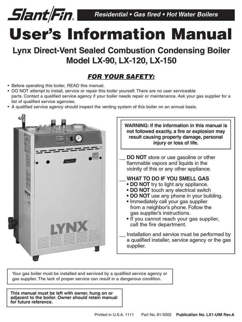
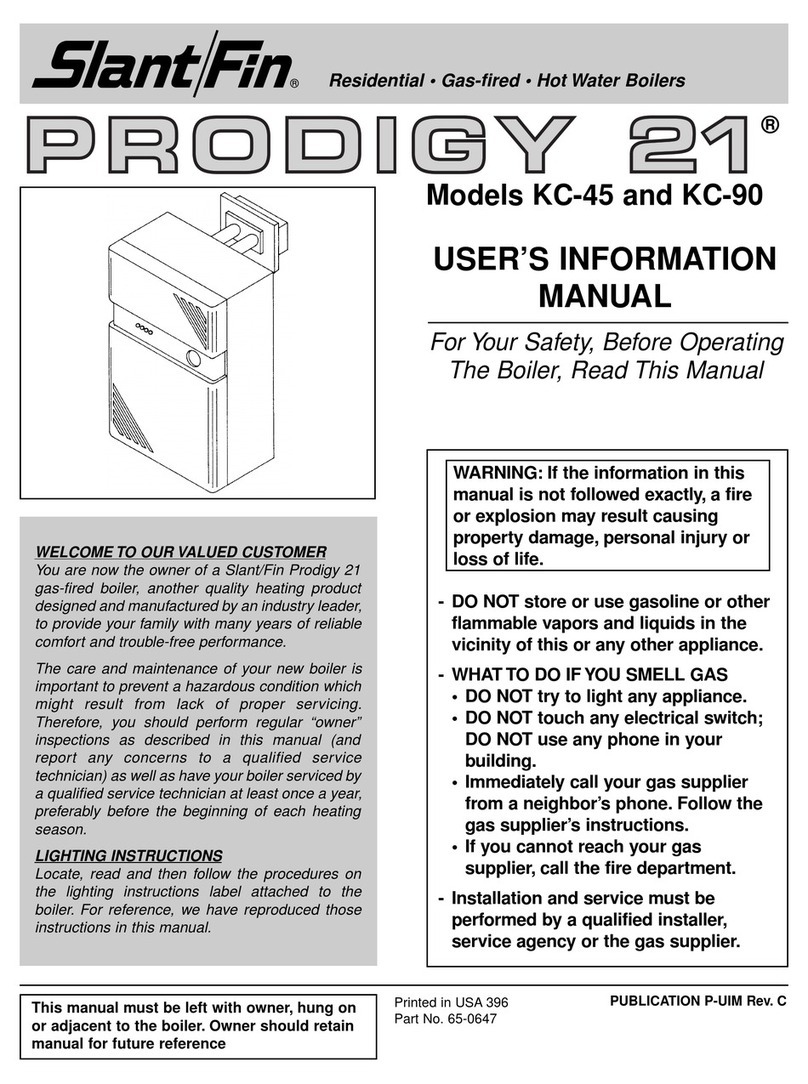
Slant/Fin Prodigy 21 KC-45 User manual

1
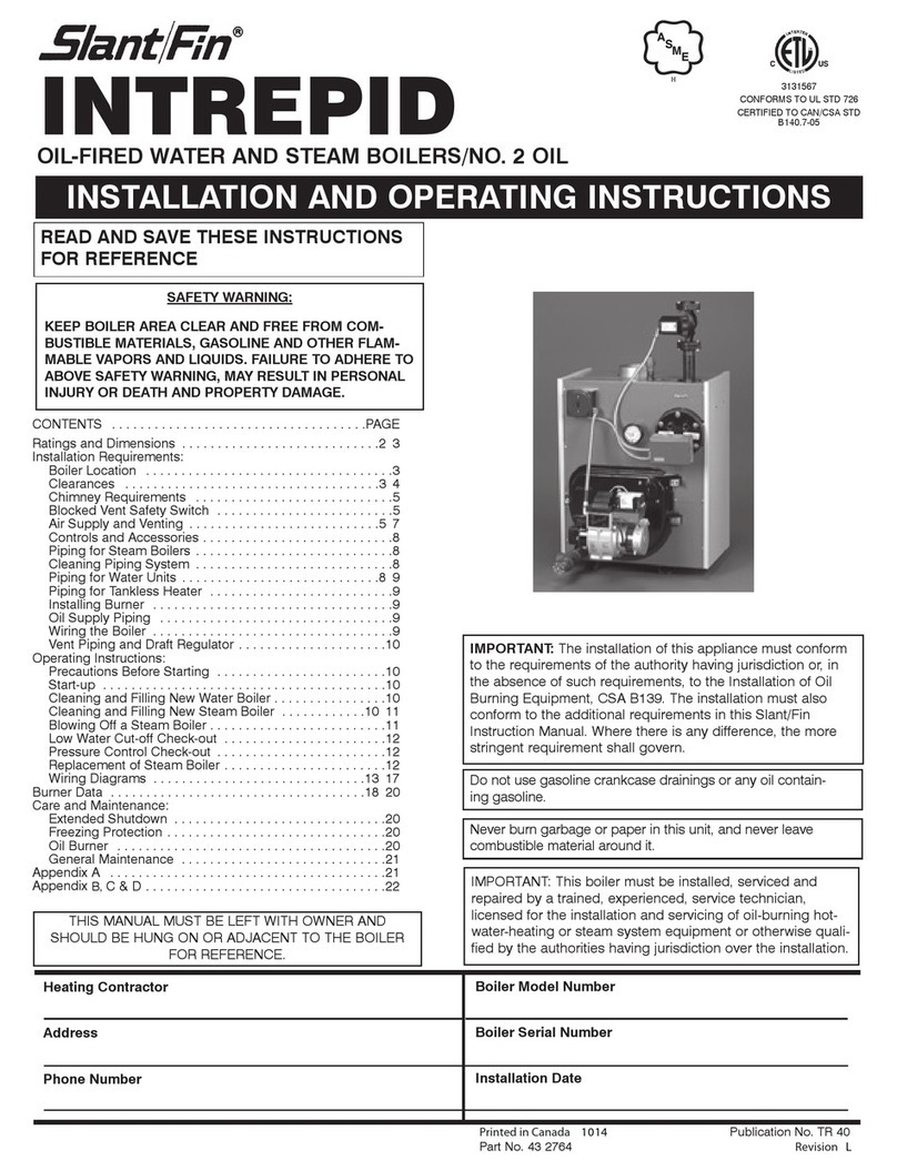
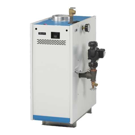
Gas-fired • Cast-iron • Hot Water Boilers
Sealed Combustion — Direct Vent
WALL MOUNT
HOT WATER BOILER
INSTRUCTION MANUAL
Contents...............................................Page
•Planning Ahead .........................................2
•Installation Procedures..............................4
•Operation Procedures .............................12
•Maintenance Procedures ........................15
•Troubleshooting .......................................16
REFERENCES FOR YOUR USE
Boiler Failure Codes.....................................................16
Boiler Location Requirements .......................................2
Blower Speed Calibration ...........................................13
Components Identification ............................................2
Data (Boiler) ..................................................................3
Diagnostic Indicator Light ...........................................16
Dimensions ...................................................................3
FreezeProtection.........................................................15
Gas Valve Calibration...................................................13
Indicator Light Panel ...................................................12
Input Rate Verification Procedure ...............................13
Jacket Installation ........................................................11
Lighting Instructions ....................................................20
Measuring Equipment ..................................................12
Orifice (Gas and Air) Sizes .........................................24
Purge Heating System ..................................................9
Replacement Parts .....................................................15
Safety Controls.............................................................14
Sequence of Operation ...............................................21
Thermostat Heat Anticipator .......................................11
Venting Location Requirements ....................................2
Water Treatment ..........................................................15
Wiring Diagram (Boiler) ..............................................22
Models KC-45 and KC-90
Boiler Packing List
SEE BACK PAGE OF THIS MANUAL
Additional Tools Needed
• Differential pressure gage: 0 - 1.0" w.c. range with
.02" increments.
•Plastic gage hookup tubing: 2 lengths of 3/16" I.D.
tubing with female service fitting adapters.
•Microampmeter: 0-25 microamp range with
1microamp increments.
Printed in USA 100 PUBLICATION P-40
Part No. 65-0646 Rev. G
This manual must be left with owner, hung on or
adjacent to the boiler. Owner should retain
manual for future reference.
®
2
®
PART 1: PLANNING AHEAD
Circulator, ASME #30 pressure relief valve and automatic air vent are factory mounted/wired. Low water cutoff is
factory-installed. Low water cutoff will shut off boiler in the event water falls below lowest safe water level.
BOILER LOCATION REQUIREMENTS
Boiler must be wall-mounted and can be installed on
acombustible wall. Boiler must be mounted on a
wall which provides access to the outside for choice
of venting. Boiler must not be installed on or above
carpeting.
Wall through which venting will pass must be free
and clear for opening (i.e. no hidden conduit, tele-
phone cables or other obstructions). Wall construc-
tion must be able to support the weight of boiler, pip-
ing and fill water.
For a closet installation, ventilation openings must be
provided through a door or wall to prevent excessive
heat buildup. Two openings, one near the floor and
one near the ceiling, should be sized to assure suffi-
cient air circulation in the closet (minimum 100 sq.
inches each).
Boiler must be installed so gas ignition system com-
ponents are protected from dripping or spraying
water or rain during operation and service.
VENTING LOCATION REQUIREMENTS
Vent installations shall be in accordance with Part 7,
Venting of Equipment, of the National Fuel Gas
Code,ANSI Z223.1, or applicable provisions of local
building codes.
The boiler can be vented directly through a rear wall
or through anywall within 10 feet of the right side,
left side or backof the boiler. Venting is approved for
wall thickness of 4" to 24". The boiler cannot be vent-
ed up through a roof.
Maximum vent pipe length for both the exhaust and
air intake is 10 feet external to boiler with no addi-
tional elbows other than those provided with boiler.
Vent termination must meet the following clearances:
Minimum of 12" above grade and normal snow line to
vent terminal bottom; minimum of 12" from any
building opening; minimum of 3 feet above any forced
air intake located within 10 feet; minimum of 4 feet
from electric or gas meters, regulators and relief
equipment.
Vent termination must not be located over any public
walkway, in any confined space (i.e. window wells,
alcoves, narrow alleys) or under any overhang or
deck. Vent termination should not allow flue-gas dis-
charge towards neighbor’s windows or where person-
al injury or property damage can occur.
Vent terminal is designed to deflect flue gases from
outside building wall; properly installed, it will prevent
flue-gas degradation of normal building materials.
DO NOT install the venting into a chimney or any
common venting system. DO NOT install a vent
damper or similar device in vent tubing or on the boiler.
Vent terminal provided by Slant/Fin must be used.
This vent terminal must only be mounted to an out-
side vertical wall.
3
®
Minimum Clearances
ToCombustibles
and Recommended
Service Clearances
Minimum Service
Front 6" 18"
Sides 2" 12"
Top 3" 3"
Bottom 12" 12"
Rear 0" 0"
Flue Conn.* 1-1/2" 3"
Boiler Heat Exchanger
Water Content
Model Water Content
KC-45 1/2 gal.
KC-90 1gal.
* Flue tubing must be insulated
with supplied insulation materi-
al for wall passage.
KC-45 45 22.5 9 3.5 14 11 141⁄248
1⁄241⁄291⁄233⁄4220
KC-90 90 45 9 3.5 14 11 171⁄2711
1⁄271⁄2121⁄261⁄4280
Boiler
Model
Gas Input
(MBH)
Gas Pressure (In. w.c.)
Dimensions (In.)
Natural Propane
High Low Max. Min. Max. Min. A B C D E F
Shipping
Weight
(lbs)
NOTICE: INSTALLATION AND SERVICE
MUST BE PERFORMED BY A
TRAINED AND QUALIFIED TECHNICIAN.
The installation must conform to the require-
ments of the National Fuel Gas Code ANSI
Z223.1 and the requirements of the authority
having jurisdiction as well as the requirements
in this instruction manual.
In addition, where required by the authority
having jurisdiction, installation must conform to
the Standard for Controls and Safety Devices
for Automatically Fired Boilers, ANSI/ASME
CSD-1. If there is any conflict in the above
requirements,then the more stringent require-
ment will apply.
WARNING
LIQUEFIED PETROLEUM (L.P.) PROPANE GAS-FIRED
BOILER LOCATION
REQUIRES SPECIAL ATTENTION
Liquefied Petroleum (L.P.) propane gas is heavier than air.
Therefore, propane boilers, piping, valves must NOT be installed
in locations where propane leaking from defective equipment
and piping will "pool" in a basement or other space below the
leak.
Aspark or flame from the boiler or other source may ignite the
accumulated propane gas causing an explosion or fire. Location
should be as near the vent terminal as possible so that the flue
pipe from boiler to outside is short and direct.
The UNIFORM MECHANICAL CODE may be in effect in your
geographic area.
The following precautions are cited by the 1994 UNIFORM
MECHANICAL CODE, section 304.6:
"LPG Appliances. Liquefied petroleum gas-burning appli-
ances shall not be installed in a pit, basement or similar
location where heavier-than-air-gas might collect.
Appliances so fueled shall not be installed in an above-
grade under-floor space or basement unless such location is
provided with an approved means for removal of unburned
gas."
Consult Chapter 5 of the 1994 UNIFORM MECHANICAL CODE
for design criteria of the "approved" means for removal of
unburned gas.
4
®
PART 2: INSTALLATION PROCEDURES
Boiler can be mounted on and vented directly through
an outside rear wall or mounted on an interior wall and
vented through an outside rear wall that is within 10 feet
of the back of the boiler. See Figure on Page 3.
If horizontal passage through wall is aboveboiler, vent
tubing can be extended vertically from boiler to reach
horizontal passage; full tubing length must still be within
10 feet external to boiler with no additional elbows.
If wall is frame construction, locate wall studs for mount-
ing. Suggested boiler mounting height is 32" minimum
from floor to bottom of boiler enclosure. This allows for
ease of service and/or the installation of an indirect-
fired water heater under boiler.
1. Hold mounting panel on wall (with the boiler mount-
ing studs facing out) in the location where boiler will
be positioned and level wall panel.
2. Mark the mounting bolt holes for wall panel on wall.
Use the cutout in the top of the mounting panel to
mark 9"x5" rectangular vent cutout on wall.
3. Drill mounting bolt holes for wall panel. Cut the
9"x5" opening through rear wall and do all finishing
work.
4. Secure the mounting panel (see Figure 1) to wall
using appropriate hardware: 5/16" lag bolts (provid-
ed) for frame construction wall studs; 5/16" wall
anchors or expansion plugs if construction is other
type.
5. For extended rear-wall venting only, follow the
boxed instructions above.
6. Place hex nuts (provided) loosely on the ends of
boiler mounting studs on mounting panel. (See
Figure 2.) Two keyhole-shaped slots are provided
on each side of the boiler rear which allow hex nuts
(on studs) to pass through slots. Lift the boiler and
seat it on the mounting studs. Tighten hex nuts
securely.
STEP 1A: MOUNTING BOILER WITH REAR WALL VENTING
Figure 1: Secure Mounting Panel Figure 2: Position and Secure Boiler
How To Locate Outside Wall Opening
For Extended Rear-Wall Venting
Remember, the maximum vent length is 10 feet
external to boiler with no additional elbows.
Measure the distance from floor or ceiling (whichev-
er is most level to the outside rear wall) to the center
of the vent opening.
Measure the same distance on outside rear wall
through which venting will pass. From this point,
drop the center mark 1/4" for every 1-foot of tubing
run from boiler. (Prevents condensate from flowing
back to boiler.)
Mark and cut 9"x5" opening through outside rear
wall around new center mark and do all finishing
work.
5
®
Stainless Steel
Exhaust Tubing
Copper
Air Intake
Tubing
Exhaust
Outlet
Air Intake
Inlet
1 3/4" Beyond
Both Tubes
Must
Terminate
Surface.
1 3/4"
Figure 3: Rear Wall Vent Tubing Installation
Figure 4: Copper Parts Assembly
11 3/8" Vertical Riser
Figure 5: Insulation Installation
EXHAUST/AIR INTAKE TUBING
Vent installations shall be in accordance with Part 7,
Venting of Equipment, of the National Fuel Gas Code,
ANSI Z223.1, or applicable provisions of local building
codes.
Only 2" stainless steel tubing provided by Slant/Fin
Corp. can be used for exhaust venting. 2" copper DWV
tubing for air intake can be provided from Slant/Fin or
local supplier. See Figure 3.
7. For exhaust, install the stainless steel elbowed
tubing length (provided) on the boiler exhaust out-
let, pointing toward the outside wall opening.
8. For air intake, assemble copper tubing parts (see
Figure 4) provided with boiler and install assembly
on boiler air intake inlet, pointing toward outside
wall opening.
9. For extended rear-wall venting only, complete both
of the tubing runs through outside rear wall open-
ing. Avoid routing tubing internal to walls or ceil-
ings; always allow sufficient access to tubing for
annual inspection.
10. Both tubing runs must terminate exactly 1-3/4"
beyond outside wall surface for proper insertion
into vent terminal. If necessary, cut tubing to prop-
erlength and remove all burrs.
11. Seal all tubing run joints and boiler connections
with high-temperature RTV sealant (provided).
APPLY SEALANT TO OUTSIDE OF MALE TUBE
ENDS ONLY, 1/4 inch from the tube end, not
inside of tubes or fittings.
12. If vent length exceeds 5 feet, install one vibration
isolating-type hanger on each tubing run (to pre-
vent sagging).
13. Install the insulation (provided) around stainless
steel vent pipe and secure. Insulation must cover
the vent pipe passing through the wall and termi-
nate at outside wall surface.
14. Proceed to Step 2 on Page 8.
6
®
STEP 1B: MOUNTING BOILER WITH SIDE WALL VENTING
Figure 6: Secure Mounting Panel Figure 7: Position and Secure Boiler
Boiler can be vented through an outside wall that is
within 10 feet right or left of the boiler with no addition-
al elbows.
If horizontal passage through wall is aboveboiler,vent
tubing can be extended vertically from boiler to reach
horizontal passage; full tubing length must still be with-
in 10 feet external to boiler with no additional elbows.
If wall is frame construction, locate wall studs for
mounting. Suggested boiler mounting height is 32"
minimum from floor to bottom of boiler enclosure. This
allows for ease of service and/or the installation of an
indirect-fired water heater under boiler.
1. Hold mounting panel on wall (with the boiler
mounting studs facing out) in the location where
boiler will be positioned and level wall panel.
2. Mark mounting bolt holes for wall panel on wall and
then drill mounting bolt holes for wall panel.
3. Secure the mounting panel (see Figure 6) to wall
using appropriate hardware: 5/16" lag bolts (provid-
ed) for frame construction wall studs; 5/16" wall
anchors or expansion plugs if construction is other
type.
4. Measure the distance from floor or ceiling (whichev-
er is most level to the outside side wall) to center of
9"x5" vent cutout on the wall panel.
5. Measure the same distance on the outside side wall
through which the venting will pass. This mark must
be5-1/2" from corner where the two walls adjoin.
6. From this point, drop the center mark 1/4" for every
1-foot of tubing run from boiler. (Prevents any con-
densate from flowing back to boiler.)
7. Mark and cut 9"x5" opening through the outside
side wall around new center mark and do all finish-
ing work.
8. Place hex nuts (provided) loosely on the ends of
boiler mounting studs on mounting panel. (See
Figure 7.) Two keyhole-shaped slots are provided
on each side of the boiler rear which allow hex nuts
(on studs) to pass through slots. Lift the boiler and
seat it on the mounting studs. Tighten hex nuts
securely.
EXHAUST/AIR INTAKE TUBING
Vent installations shall be in accordance with Part 7,
Venting of Equipment, of the National Fuel Gas Code,
ANSI Z223.1, or applicable provisions of local building
codes.
Only 2" stainless steel tubing provided by Slant/Fin
Corp. can be used for exhaust venting. 2" copper
DWV tubing for air intake can be provided from
Slant/Fin or local supplier.
9. For exhaust, install the stainless steel elbowed tub-
ing length (provided) on the boiler exhaust outlet,
pointing toward outside wall opening.
7
®
10. For air intake, assemble copper tubing
parts (see Figure 9) provided with boiler
and install the assembly on boiler air
intake inlet, pointing toward outside wall
opening.
11. Complete both tubing runs through out-
side side wall opening. Avoid routing tub-
ing internal to walls or ceilings; always
allow sufficient access to tubing for
annual inspection.
12. Both tubing runs must terminate exactly
1-3/4" beyond the surface of the outside
wall for proper insertion into vent termi-
nal. If necessary,cut the tubing to proper
length and remove all burrs.
13. Seal all tubing run joints and boiler con-
nections with a high-temperature RTV
sealant (provided). APPLY SEALANT TO
OUTSIDE OF MALE TUBE ENDS ONLY,
1/4 inch from the tube end, not inside of
the tubes or fittings.
14. If vent length exceeds 5 feet, install one
vibration isolating-type hanger on each
tubing run (to prevent sagging).
15. Install the insulation (provided) around
stainless steel vent pipe and secure.
Insulation must cover the vent pipe pass-
ing through the wall and terminate at
outside wall surface.
Figure 9: Copper Parts Assembly
Figure 8: Side Wall Vent Tubing Installation
Figure 10: Insulation Installation
8
®
STEP 2: INSTALL OUTSIDE VENT TERMINAL
Figure 11: Wall Plate Installation Figure 12: Vent Terminal Box Installation
VENT TERMINAL INSTALLATION
Warning: The vent terminal provided must be used.
DO NOT alter this part in any manner other than as
shown in these instructions. This vent terminal can
only be mounted on a vertical surface.
1. Checking tubing installation
a) Both exhaust and air intake tubes should extend
1-3/4” beyond outside wall surface.
b) Insulation on exhaust tube should be flush with
outside wall surface.
2. Check tubing orientation
a) Air inlet tubing may be located to the left or to
the right of the exhaust tube, depending on
which direction the tubes were run from the boil-
er.
b) If the air inlet tubing is to the left of the exhaust
(viewed from outside of building), then the vent
terminal may be installed as supplied without
alteration.
c) If the air inlet tubing is to the right of the exhaust
(viewed from outside of building), then the air
inlet cover must be removed and reinstalled over
the slots on the opposite side of the vent termi-
nal. This alteration will ensure that the air inlet
openings will face down when the vent terminal
is installed.
3. Prepare outside wall
a) Position vent terminal up to wall cutout so that
both exhaust and air intake tubes are inserted
into the terminal’s back openings.
b) Check that the wall mounting plate overlaps the
wall passage cutout on both sides for proper
sealing to wall.
c) Check that the terminal itself is level and that its
position ensures a 1/4” per foot downward pitch
of the tubing from the boiler.
d) Mark and drill out the location of the four screw
holes in the wall for mounting the vent terminal.
4. Install wall mounting plate
a) Separate wall mounting plate from vent terminal
box by unscrewing the two screws on both sides
of the terminal.
b) Run a bead of silicone around the inside perime-
ter of the back of the wall plate.
c) Slide the wall plate over the tubes and screw it
securely to the outside wall. Check that the plate
is flush and sealed to the wall around its perime-
ter.
d) Run a bead of RTV high-temperature sealant
around the tubes, both where they pass through
the wall plate and also about 1/4” from the end of
each tube for sealing the vent terminal box in the
next step.
5. Install vent terminal box
a) Place the vent terminal box over the tubes and
reattach to the wall mounting plate with the
screws removed in step 4.
b) Makesure the terminal is orientated so that the
air intake tube inserts into the side of the termi-
nal with the air intake openings, and that these
openings face downward and the air intake cover
is facing upward.
c) Make sure that both the air intake and exhaust
tubes insert into the vent terminal box and are
sealed properly.
RUN BEAD OF SILICONE
AROUND INSIDE PERIMETER
ON BACK OF WALL PLATE.
EXHAUST TUBE
SEPARATE WALL PANEL
FROM VENT TERMINAL BOX
BYREMOVING SCREWS.
AIR INLET
TUBE
INSULATION
WALL
P
ASSAGE
CUTOUT
AIR INLET COVER
( FACES UP )
AIR INLET OPENINGS
(FACE DOWN )
EXHAUST TUBE
AIR INLET TUBE
SILICONE
BEADS
9
®
STEP 3: INSTALL EXPANSION TANK AND WATER PIPING
Expansion
Tank
Tank
Support
Bracket
Expansion
Tube
Tank Strap
Relief
Valve
Discharge
Supply
Water
Outlet
3/4"NPT
3/4"NPT
Return
Water Inlet
3/4"NPT
Return
Drain Valve
For Boiler
Supply
Shutoff
Valves
Pressure
Reducing
(Fill) Valve
Shutoff
Valve
Valves
Zone
Figure 14:
Expansion
Tank and
Piping
Connections
Note: Factory-
installed low
water cutoff
will shut off
boiler in the
event water
falls below the
lowest safe
water level.
Always follow good piping practices. Observe minimum
1" clearance to combustibles around all uninsulated hot
water pipes or when openings around pipes are not
protected by non-combustible materials.
Boiler must not be connected to a chiller. If the boiler
supplies hot water to heating coils in air handling units,
flow control valves or other devices must be installed to
prevent gravity circulation of boiler water in the coils
during the cooling cycle.
NOTICE: USE PIPE DOPE SPARINGLY AND SPREAD
AROUND MALE PIPE THREADS ONLY.
Expansion Tank: (Provided) To install, see Figure 14.
Piping systems with unusually large water volume may
require the connection of a larger capacity expansion
tank outside of the boiler’s enclosure.
Relief ValveDischarge Piping: Install behind supply
water pipe. Use same size or larger piping (iron or cop-
per) than valve outlet. Must terminate 6" from floor (or
local codes) with a plain (no threads) end. DO NOT
hard-pipe to drain piping. Make sure discharge is
always visible.
Cold Water Fill: Pressure reducing (fill) valve and shutoff
valve should be installed.
Supply and Return: For tapping sizes, see dimensions
on Page 3. Recommend shutoff valve in supply (and
shutoff and drain valves in return on non-zoned sys-
tem).
Radiant Floor and Standing Iron Radiant Systems:A
boiler by-pass loop (or equivalent) will be required to
avoid flue gas condensation on cast iron sections for
low temperature application. (i.e. radiant floor systems.)
Zone Piping: See Page 20 for zoning with zone valves
and domestic hot water installation.
STEP 4: FILL AND PURGE HEATING SYSTEM
•Make sure flow direction arrows on components are
facing in direction of flow.
•Place bucket under pressure relief valve discharge.
BASEBOARD AND RADIANT FLOOR SYSTEMS
•Close all shutoff valves, drain valves and air vents.
•Open supply shutoff valve and return drain valve on
first zone (or return drain valve on non-zoned system).
If zoned with zone valves, manually open zone valve.
•Attach a hose from return drain valve to a drain. Open
fill line shutoff valve. Manually operate fill valve regula-
tor. When water runs out of hose in a steady stream
(with no air bubbles), close return drain valve.
•Repeat procedure for additional zones (one at a time).
•On completion, open all return shutoff valves.
STANDING IRON RADIATION AND SYSTEMS WITH
MANUAL VENTS ATHIGH POINTS
•Close all shutoff valves, drain valves and air vents.
•Open supply and return shutoff valves. If zoned with
zone valves, manually open all zone valves.
•Open fill line shutoff valve. Manually operate fill valve
regulator. Open pressure relief valve manual operator
to fill boiler. When water runs out of discharge pipe in
steady stream (with no air bubbles), close operator.
•Starting with nearest manual air vent, open vent until
water flows out; close vent. Repeat procedure, working
your way toward farthest air vent.
WHEN FINISHED
•Place fill valve regulator and all zone valve operators
in automatic position.
•Check that temperature/pressure gage reads minimum
of 12 psi (fill pressure); exact pressure will vary with
altitude. If piping system rises more than 16 feet verti-
cally above boiler, higher fill pressures are required.
•Check for and repair any water leaks.
10
®
STEP 5: SELECT GAS PIPE SIZE
Install Manual
Main Shutoff
Above Floor
When Required
By Local Code
Valve 5 ft.
Gas
Supply
Gas Valve
Union
Full Size
Sediment
Trap
Figure 15: Gas Piping Component Locations
•Measure length of piping from gas meter to farthest
appliance on gas line. MEASURE BOTH VERTICAL
AND HORIZONTAL RUNS. This is the only measure-
ment required regardless of which portion of the gas
piping is being sized. No allowance required for fit-
tings.
•Using sizing table below, enter table at top with num-
ber of running feet.
•Read down and match boiler’s input to capacity
(cu.ft./hr). If the input falls between two numbers,
always use higher capacity.
•Read across to left side of table for correct pipe size.
Example: Prodigy Model KC-90, with 90,000 input, will
be installed. Measured length of piping is 30 feet. From
chart, a “matched” capacity would be 152; so, pipe size
would be 3/4".
STEP 6: INSTALL AND TEST GAS PIPING SYSTEM
Where it’s applicable, local codes supercede these
instructions. Always follow good piping practices.
Inspect piping thoroughly for cleanliness before make-
up. Pipe dope must be compatible with gas (NG or LP).
NEVER use teflon tape or hard-setting compounds.
NOTICE: USE PIPE DOPE SPARINGL
YAND SPREAD
AROUND MALE PIPE THREADS ONLY.
Gas Piping Components: Install piping from gas meter
to boiler with a manual main shutoff valve (recommend
afull port, ball-type valve approved for use with gas), a
ground joint union and full size sediment trap.
Piping Supports: Horizontal piping must be supported
by hangers, not by the boiler or accessories. Space
hangers 8 feet apart (or local codes).
GAS SUPPLY PRESSURE
Minimum and maximum gas supply pressure to the gas
valveis provided on the boiler rating plate. Check local
utility for pressure being supplied. If pressure is below
minimum, contact the gas utility. If pressure is above
maximum, install a 100% lock-up gas pressure regula-
tor in gas supply line and adjust to maximum boiler gas
pressure.
LEAK TEST GAS PIPING
For test pressures of 13" w.c. or less, isolate the boiler
from gas piping byclosing the manual main shutoff val-
ve. For test pressures greater than 13" w.c., disconnect
boiler gas valve from the gas piping. Pressurize the gas
piping and bubble test all piping and boiler connections
for leaks using soap solution.
DANGER: DO NOT USE FLAME TO CHECK FOR
GAS LEAKS. FIRE OR EXPLOSION CAN RESULT.
10 20 30 40 50 60 70 80 90 100 125 150 175 200
3⁄4” 278 190 152 130 115 105 96 90 84 79 72 64 59 55
1” 520 350 285 245 215 195 180 170 160 150 130 120 110 100
11⁄4” 1050 730 590 500 440 400 370 350 320 305 275 250 225 210
11⁄2” 1600 1100 890 760 670 610 560 530 490 460 410 380 350 320
2” 3050 2100 1650 1450 1270 1150 1050 990 930 870 780 710 650 610
Schedule
40
Pipe
Size
Maximum Capacity of Pipe (cu.ft./hr.) for Gas Pressures of 0.5 psig or Less
and Pressure Drop of 0.3” W.C. (Based on 0.60 Specific Gravity Gas)
11
®
STEP 7: INSTALL POWER AND THERMOSTAT WIRING
LO
HI
FT1 FT2 T1 T2 A1 A2
AUTO/MAN
CAL/OP
LO/HI
Thermostat & Alarm Terminals
Figure 16: Electronic Boiler Control Board
DANGER: BEFORE WIRING, ALWAYS TURN OFF
ELECTRIC POWER SUPPLY. OTHERWISE, SHOCK
OR DEATH CAN RESULT.
WARNING: DO NOT USE BOILER TRANSFORMER
TO POWER EXTERNAL ACCESSORIES (i.e. ZONE
VALVES, RELAYS). OVERLOADED/BURNED-OUT
TRANSFORMER CAN RESULT.
WARNING: DO NOT CONNECT WIRES CARRYING
POWER FROM AN EXTERNAL SOURCE TO THER-
MOSTAT OR AQUASTAT TERMINALS. SEVERE DAM-
AGE TO THE CONTROL BOARD CAN OCCUR.
Boiler must be electrically grounded in accordance with
the requirements of the authority having jurisdiction or,
in the absence of such requirements, with the National
Electrical Code, ANSI/NFPA 70.
Power Supply: A separately fused circuit is recommend-
ed. Use a standard 15-amp fuse or breaker and 14-
gauge conductors in BX cable or conduit.
Thermostat Connections: The boiler will run at high or
low fire, depending on space heating needs, when the
T1 and T2 terminals are closed. Connect low voltage
wiring from space heating zones to T1 and T2 terminals
on control board. Wire connections to T1 and T2 termi-
nal block must be from an isolated circuit. DO NOT
BRING VOLTAGE FROM AN EXTERNAL SOURCE
HERE. Wires should be only run from thermostats, zone
valve end switches, or circulator end switches. 3 wire
zone valves which do not have isolated end switches
cannot be used unless a relay is added with the dry
contacts wired to T1 and T2.
Thermostat Heat Anticipator: For zoned system, set to
match amp draw of zone valve or circulator relay. For a
non-zoned system, set to .3 amps.
Circulator Relayon Board: DO NOT exceed 5
amp/120V max. rating.
Wiring Diagrams: See index on Page 20 for zoning with
zone valves, indirect-fired water heater and reference
boiler diagram.
OPTIONS AVAILABLE
Domestic Hot Water Installation: The boiler will run at
high fire mode for maximum recovery of the Storage
Tank when the A1 and A2 terminals are closed.
Connect zone valve end switch to A1 and A2 terminals
on electronic boiler control board. Water heater thermo-
stat operates zone valve. DO NOT bring power from an
external source to these terminals. Note: 3 wire zone
valves which do not have isolated end switches cannot
be used unless a relay is added with the dry contacts
wired to T1 and T2.
AlarmSystem: A remote-type alarm device may be con-
nected to the boiler that will be activated if the boiler
shuts down due to a malfunction. FT1 and FT2 termi-
nals on electronic boiler control board are a dry contact
(5 amp 120 V max) that makes on a system fault or
power outage.
STEP 8: INSTALL JACKET ENCLOSURE
Power Connections
•Remove electrical junction box cover.
•HOT CONNECTION LEAD IS BLACK.
•NEUTRAL CONNECTION LEAD IS WHITE.
•Connect ground inside box.
DO NOT REVERSE POWER CONNECTIONS; if
reversed, ignition control will not detect a flame and
will go into safety shutdown.
The jacket can also be installed after start-up proce-
dures. Jacket components include boiler enclosure and
front cover.
TOINSTALL BOILER ENCLOSURE
•For side wall venting ONLY, remove appropriate vent
side panel from enclosure (located at top of sides).
•Place enclosure top over top flange of wall panel.
•Slide down until slots (on the insides of enclosure) are
seated in support brackets on mounting panel.
• Attach sheet metal enclosure to wall panel on both
sides with screws.
TOINSTALL FRONT COVER
•Insert the slots in cover bottom over support clips on
sheet metal enclosure bottom.
•Line up temperature/pressure indicator and push
cover in until support clip (at enclosure top) snaps
into slot on cover top.
• Install the 4 LED window plugs into the front cover
holes (if not factory installed).
12
®
PART 3: OPERATION PROCEDURES
INDICATOR LIGHT PANEL
STEP 1: SET UP MEASURING EQUIPMENT
BOILER STATUS
POWER DIAGNOSTIC FULL REDUCED
FUEL UTILIZATION RATE
Figure 17: Indicator Lights Identification
LED indicator lights provide important information about
boiler operation at a glance. When the CAL/OP selec-
tor switch (see Step 1 below) is UP in the OP position,
the lights indicate as follows:
Power Indicator (RED): Steady ON means there is elec-
trical power to the boiler. Light will come on when power
is provided to boiler.
Diagnostic Indicator (RED): Steady ON or intermittent
flashing indicates a system operation problem.
Full Rate Indicator (AMBER): Steady ON means boiler
is running in high-fire mode. Light will come on when
the boiler starts up; will go off when boiler switches to
low-fire mode or shuts off.
Reduced Rate Indicator (GREEN): Steady ON means
the boiler is running in low-fire mode. Light will come on
when boiler automatically switches to low-fire mode; will
go off when boiler returns to high-fire mode or shuts off.
Note: When the CAL/OP selector switch is DOWN in the
CAL position, the amber and green lights indicate pres-
sure switch closure at high and low blower speeds.
Adifferential pressure gage is necessary to calibrate
the blower speed and the gas valve to assure the prop-
er air-gas ratio when the boiler is operating.
CALIBRATION EQUIPMENT:
Pressure measurement fittings: There are 3 service
fittings with caps provided on this boiler for convenient
calibration of the air/gas ratio and input in the field.
See Figure 18 for the location of each.
Pressure measurement gage: Magnehelic or Incline
differential pressure gage with 0 - 1.0" w.c. range and
0.02" increments recommended.
Available from Slant/Fin is a calibration gage kit (part
number 665185) that has a gage mounted on a stand
with a “toggling” feature which allows the user to switch
between the blower and gas valve calibration without
moving the tubing connections.
T
ubing and connectors for gage: Need 2 lengths of
3/16" I.D. plastic tubing with female adapters which
mate to the service fittings.
• Mount gage securely, within reach of all tubing. Make
sure it’slevel so the meter indicates “zero” or can be
adjusted to do so. HI/LO sides marked on the gage.
•Calibration also requires using boiler Operation
Selector Switches and Blower Speed Adjustment
Pots, located on the Electronic Boiler Control Board
(see Figure 19).
Figure 18: Locations of Pressure Measurement Fittings
LO
HI
FT1 FT2 T1 T2 A1 A2
AUTO/MAN
CAL/OP
LO/HI
Operation Selector Switches
Blower Speed Adjustment Pots
Figure 19: Electronic Boiler Control Board
Switch# Position Operation Description
1 Down AUTO Automatic Boiler Operation
1 Up MAN Manual Boiler Operation
2 Down CAL Calibration Procedures -
Blower Runs Gas Valve
WILL NOTOPEN
2 UP OP Normal Boiler Operation
3 Down LO Low Fire Operation
3 Up HI High Fire Operation
Operation Selector Switches
13
®
STEP 2: CALIBRATE BLOWER SPEED
• Connect tubing to differential pressure gage as fol-
lows:
1.From Blower Outlet Pressure Fitting on MIXING
ELBOW to GAGE HI side.
2.From BURNER ENCLOSURE Pressure Fitting to
GAGE LO side.
FOR HIGH FIRE OPERATION:
• Set the Operation Selector Switches as follows:
Switch 1 (left) UP MAN
Switch 2 (center) DOWN CAL
Switch 3 (right) UP HI
•Turn power ON. (Red power light and amber full rate
light will come on. Blower will start.)
•Allow about 30 seconds for pressure to stabilize.
•Read gage. Reading should be 1.00" w.c.
•Adjust as necessary. Using HI Blower Speed
Adjustment Pot, turn in small increments (clockwise to
increase reading or counterclockwise to decrease the
reading). Allow to stabilize between adjustments.
FOR LOWFIRE OPERATION:
• Set the Operation Selector Switch 3 to DOWN, LO
position. (Amber light goes off, green reduced rate
light comes on.)
•Allow about 30 seconds for pressure to stabilize.
•Read gage. Pressure reading should be 0.25" w.c..
• Adjust as necessary. Using LO Blower Speed
Adjustment Pot, turn in small increments (clockwise to
increase reading or counterclockwise to decrease the
reading). Allow to stabilize between adjustments.
STEP 4: CHECK BOILER INPUT RATE
NOTICE: DO NOT USE GAS VALVE TO ADJUST
INPUT RATE. FOLLOW DIRECTIONS BELOW.
•Consult gas supplier for heating value of gas (usually
1000 Btu/cu.ft. for NG; 2500 Btu/cu.ft. for LP).
•Place the jumper across the T1-T2 terminals and
allow the boiler to operate 10 minutes.
•Shut off all other appliances served by gas meter dur-
ing timing of input rate.
FOR HIGH FIRE OPERATION:Set the Operation
Selector Switches to MAN, OP and HI.
•At meter, observe number of cubic feet of gas the boil-
er uses in 3 minutes.
•Verify input using following formula:
Cu.Ft. in 3 mins. x Heating Value x 20 = Btu/hr Input
Example: 4.5 cu.ft. x 1000 x 20 = 90,000 Input
FOR LOWFIRE OPERATION:Set Operation Selector
Switch 3 to LO position.
•Allow operation to stabilize.
•At meter, observe number of cubic feet of gas boiler
uses in 3 minutes. Verify input using same formula.
Example: 2.25 cu.ft. x 1000 x 20 = 45,000 Input
IF ADJUSTMENTS NECESSARY:Turn Blower Speed
Adjustment Pot (HI for high-fire or LO for low-fire) in
small increments,clockwise to increase input or coun-
terclockwise to decrease input. Allow for stabilization of
operation between adjustments.
STEP 3: CALIBRATE GAS VALVE (First Light-Off)
PURPOSE OF GAS VALVE CALIBRATION IS TO
ADJUST AIR-GAS RATIO ONLY - NOT INPUT.
•Connect tubing to differential pressure gage as fol-
lows:
1. From Blower Outlet Pressure Fitting on MIXING
ELBOW to GAGE HI side.
2. From GAS VALVE OUTLET Pressure Fitting to
GAGE LO side.
•Disconnect any wires from T1, T2 and A1-A2 termi-
nals and set up a jumper wire across T1-T2 terminals
to control operation at boiler. Open zone valves.
FOR LOWFIRE OPERATION:
•Set the Operation Selector Switches as follows:
Switch 1 (left) UP MAN
Switch 2 (center) UP OP
Switch 3 (right) DOWN LO
• Open manual main gas shutoff valve and turn boiler
gas valve ON.
•Place the jumper across the T1 and T2 terminals.
• After about 20 seconds, boiler will start. (Green
reduced rate light on.)
•Allow about 30 seconds for pressure to stabilize.
•Read gage. Reading should be 0" w.c. ±0.01".
•Adjust as necessary. Remove round screw cap cover-
ing gas valve adjustment. Position screwdriver into
adjustment screw slot carefully. Observe gage while
adjusting and turn screw slowly. Turn adjustment
screw clockwise to decrease reading if over 0 set-
point. Turn adjustment screw counterclockwise to
increase reading if under 0 setpoint.
Note: Remember that the gas pressure is on the low
side of the gage. Consequently, decreasing the differen-
tial reading actually is INCREASING the gas pressure
reading, since the blower outlet pressure is on the high
side of the gage and not changing.
FOR HIGH FIRE OPERATION:
• Set Operation Selector Switch 3 (right) to the UP, HI
position. (Green light goes off. Amber full rate light
comes on.)
• Allow about 30 seconds for pressure to stabilize.
•Read gage. Pressure reading should be about 0"
w.c. ±0.05". If reading slightly off “zero”, DO NOT re-
adjust gas valve. This would alter the more critical low
setting. This step is done only to check boiler rate
switching ability.
• REPLACE SCREW COVER ON GAS VALVE
ADJUSTMENT
. Double check gage reading with
cover on.
• Disconnect gage adapters and replace service fitting
caps hand tight.
• If gas meter available, proceed to Step 4.
14
®
STEP 5: SETUP SYSTEM FOR AUTOMATIC OPERATION
FOR INITIAL START-UP ONLY
•Remove jumper from across T1-T2 terminals and
reconnect wires to control board T1-T2 and A1-A2
terminals properly.
•Restore zone valves to automatic operation.
•Set thermostat(s) to call for heat.
•Set selector switches to AUTO, OP and HI.
FOR NORMAL SYSTEM START-UP
•Set selector switches to AUTO, OP and HI.
•Follow lighting instructions attached to boiler.
See index on Page 20 for reference lighting instructions
and sequence of operation.
Safe lighting and other performance criteria were met
with the gas manifold and control assembly provided on
the boiler when the boiler underwent tests specified in
ANSI Z21.13.
STEP 7: TEST COMMON VENTING SYSTEM (IF REQUIRED)
If existing boiler was removed from a common venting
system, common venting system may be too large for
proper venting of appliances remaining connected to it.
At the time of removal of existing boiler, the following
steps shall be followed with each appliance remaining
connected to common venting system placed in opera-
tion, while the other appliances remaining connected to
the common venting system are not in operation.
1. Seal any unused openings in common venting sys-
tem.
2. Visually inspect venting system for proper size and
horizontal pitch and determine there is no blockage
or restriction, leakage, corrosion and other deficien-
cies which could cause an unsafecondition.
3. Insofar as is practical, close all building doors and
windows and all doors between the space in which
the appliances remaining connected to the common
venting system are located and other spaces of build-
ing. Turn on clothes dryer and any appliance not con-
nected to common venting system. Turn on any
exhaust fans, such as range hoods and bathroom
exhausts, so they will operate at maximum speed.
DONOT operate a summer exhaust fan. Close fire-
place dampers.
4. Place in operation the appliance being inspected.
Follow the lighting instructions. Adjust thermostat so
appliance will operate continuously.
5. Test for spillage at the draft hood relief opening after
5minutes of main burner operation. Use the flame of
amatch or candle, or smoke from cigarette, cigar or
pipe.
6. After it has been determined that each appliance
remaining connected to common venting system
properly vents when tested as outlined above, return
doors,windows, exhaust fans, fireplace dampers and
anyother gas-burning appliances to their previous
condition of use.
7. Any improper operation of common venting system
should be corrected so installation conforms with
National Fuel Gas Code ANSI Z223.1. When resizing
any portion of the common venting system, common
venting system should be resized to approach mini-
mum sizeas determined using appropriate tables in
Part II in National Fuel Gas Code ANSI Z223.1.
STEP 6: CHECK SYSTEM OPERATION
PurgeAir One Final Time
•Let system water reach 160°. Temperature/pressure
gage should be between 12 and 25 psi.
•Bleed all air vents until water squirts out; start on low-
est floor with first air vent in the line of flow.
CheckExhaust and Air Intake Venting
•Check for and reseal any vent tubing leaks.
•Check for and remove any vent terminal obstructions.
CheckGas Valve Operation (With Burner Firing)
USE CAUTION - LINE VOLTAGE PRESENT.
•Disconnect flame sensor wire lead from flame sensor
tab. Gas valve should close.
•It is normal for boiler to re-try for ignition (3 times)
with wire removed from flame sensor, but gas valve
should only open for a few seconds during each re-try
and be closed between trials.
•Replace flame sensor wire lead on flame sensor tab.
CheckHigh Limit Operation
HIGH LIMIT CANNOT BE SET BELOW 180°. HIGHEST
MAXIMUM ALLOWABLE SETTING IS 220°.
•Set thermostat high enough for the water temperature
to reach limit switch setting of 180°.
•When reached, limit switch should open and gas
valve should close.
15
®
PART 4: MAINTENANCE PROCEDURES
This section must be brought to the owner’s attention,
sothe owner can make necessary arrangements with a
trained and qualified service technician for periodic
maintenance of this boiler. Installer must also inform
owner that the lack of proper care and maintenance of
this boiler may result in a hazardous condition. Installer
should discuss contents of the User’s Information
Manual with the owner.
KEEP THE BOILER AREA CLEAR AND FREE FROM
COMBUSTIBLE MATERIALS, GASOLINE AND OTHER
FLAMMABLE VAPORS AND LIQUIDS.
BEFORE EACH HEATING SEASON
Atrained and qualified service technician should per-
form the inspections listed in these instructions at least
once a year.
Vent Terminal: Check for and remove obstructions.
Closet Installations: Check for and remove ventilation air
opening obstructions.
Vent Tubing: Check for and repair leaks or sagging.
Exhaust Tubing (Externally): Check for corrosion. To
inspect, remove insulation. If corrosion is present,
replace and reseal exhaust tubing assembly and insula-
tion.
Exhaust and Air IntakeTubing (Internally): Check for
and remove obstructions. To inspect, remove tubing
from boiler. When finished, reseal all removed tubing
parts with high-temperature RTV sealant and replace
insulation.
Heat Exchanger: In the unlikely event of boiler flue pas-
sage blockage, service to remedy situation must be per-
formed only by an authorized Slant/Fin representative.
Burner: In the unlikely event of burner sooting or block-
ages, service to remedy situation must be performed
only by an authorized Slant/Fin representative.
System Water: Check that the system is full of water
and properly pressurized. Check for and correct radia-
tion system air “noise”.
Water Piping: Check for and repair any leaks.
Gas Piping: Check for and repair any leaks.
Safety Shutdown Controls: Check operation as detailed
on Page 14 in this manual.
Air Filter: Replace (recommended) or clean annually
(more often if conditions dictate). Slant/Fin replacement
air filter, part number 65-0524 must be used. Can be
cleaned with soap and water; after drying, spray with an
adhesive-type air filter spray which will attract/hold air-
borne dust particles.
Blower and Circulator: These are sealed components
and do not require lubrication.
WATER TREATMENT
Agood water treatment program will extend the useful
life of the boiler and is especially recommended in
areas where water quality is a problem. A reputable
water treatment company should be consulted for deter-
mining the best overall treatment program for this equip-
ment.
FREEZE PROTECTION
If anti-freeze must be used, INHIBITED PROPYLENE
GLYCOL is recommended as it is practically non-toxic.
For useful information on the characteristics and mixing
proportions of anti-freeze in heating systems, obtain a
copyof Technical Topics No. 2A from Hydronics
Institute,34 Russo Place,Berkeley Heights, NJ 07922.
WARNING: DO NOT USE ETHYLENE GLYCOL,
AN AUTOMOTIVE-TYPE OR UNDILUTED ANTI-
FREEZE. SEVERE BOILER DAMAGE CAN RESULT.
REPLACEMENT PARTS
When parts are needed, refer to Slant/Fin’s Prodigy
Replacement Parts List furnished with the boiler. If not
available, contact local Slant/Fin wholesaler or Slant/Fin
Corporation, Greenvale, NY.
Control identification and replacement should not be
attempted by unskilled personnel. Only the simple, easi-
ly-identified controls and parts can be obtained locally.
All other controls and parts may have to be ordered
from Slant/Fin. Pressure relief valve must be ASME
rated for the pressure and gross output of the boiler.
This boiler is equipped with an unconventional gas con-
trol. If this control is replaced, it must be replaced with
an identical gas control and calibrated as specified in
the Operation Procedures.
Replacement parts are available from:
Slant/Fin Corp.
100 Forest Drive
Greenvale, NY 11548
16
®
PART 5: TROUBLESHOOTING
DIAGNOSTIC INDICATOR LIGHT (RED)
Carefully note red diagnostic indicator light. When a
system failure occurs, indicator light will show a series
of quick flashes with a short interval between the series
when indicator stops flashing. Count the number of
flashes that occur after the short no-flashing interval.
Correct failure code for each number of flashes is
shown in box.
If the diagnostic light is off when service technician
arrives, set thermostat to call for heat. Boiler will attempt
restart. (Boiler also attempts restart each hour during
failure mode and after a power interruption.) If the boiler
restarts, the diagnostic light will stay off. If the boiler
does not restart, the diagnostic light will return to either
Steady On or the series of flashes.
Boiler Failure Codes ........................Page
Continuous Flashing
---------Electronic Control Failure . . . . . . . . . . . 17
1Flash----------High Limit Open 1 Hour. . . . . . . . . . . . . 17
2Flashes ------No Ignition . . . . . . . . . . . . . . . . . . . . . . 17
3Flashes ------Pressure Switch Problem . . . . . . . . . . . 17
4Flashes ------Hot Surface Ignitor Failure. . . . . . . . . . . 18
5Flashes ------Blower RPM Too Low . . . . . . . . . . . . . . 18
6Flashes ------Low Water Cutoff Open . . . . . . . . . . . . . 18
7Flashes ------Improper Flame Signal . . . . . . . . . . . . . 18
Steady ON-----Loss Of Flame Signal . . . . . . . . . . . . . . 18
Figure 20:
Boiler
Components for
Troubleshooting
LO
HI
FT1 FT2 T1 T2 A1 A2
AUTO/MAN
CAL/OP
LO/HI
Upper 120v.
Connector
LED#1 - Blower RPM
Combustion
Blower Motor
LED#2 - Gas Valve
Flame Current Jack
Hot Surface
Ignitor
Figure 21: Electronic Control Board Components For Troubleshooting
NOTICE: ANY WIRES CUT WHILE
SERVICING MUST BE ROUTED TO
AND SPLICED INSIDE THE BOILER
JUNCTION BOX OR SEPARATE
JUNCTION BOX.
17
®
DIAGNOSTIC “1 FLASH” - HIGH LIMIT OPEN 1 HOUR
DIAGNOSTIC “Continuous Flashing” - ELECTRONIC CONTROL FAILURE
CAUSE
High Limit Is
Defective?
Circulator Not
Running?
Zone Valves Not
Opening?
TEST
Set high limit above boiler water temperature (raise limit
setting substantially as water temperature may be higher
than gage reading when there is no water flow through
boiler). Check for continuity across high limit contacts.
With thermostat calling for heat, check for power to circu-
lator. If no power, check wiring connections to circulator.
With thermostat calling for heat, check for power to each
valve. If no power, check wiring connections to valve.
Electronic Control Is
Defective.
Control board cannot be serviced. Replacement must be same manufacturer and model. After replace-
ment, calibrate blower speed as shown in Part 3 in manual.
SOLUTION
Ifcontacts remain open, replace high
limit. Replacement must be same manu-
facturer and model. DONOT set above
220°.
If power OK, but circulator not running,
replace circulator.
If power OK, but valve not opening,
replace valve.
DIAGNOSTIC “2 FLASHES” - NO IGNITION
(No Flame Signal After Trial For Ignition)
No Gas Supply To
Gas Valve?
No Gas Supply To
Burner?
Air-Gas Ratio Is Not
Proper?
Orifice Sizing Is Not
Correct?
Electrical
Connections Are
Loose or Reversed?
Flame Sensor
Current Is Weak?
Flame Sensor Is
Defective?
Check that manual gas shutoff is open. Check for gas sup-
ply pressure to valve.
Checkgas valve knob in ON position. Check wiring and
tubing connections to valve. Check for power to gas valve.
Note gas valve LED on control board (see Figure 21).
Check valve outlet pressure to determine if valve is open-
ing (see “How To Do It” on Page 19).
Checkgas valve calibration as shown in Part 3 in manual.
Check gas and air orifice size (see “How To Do It” on Page
19).
Check power wiring to electronic board, (hot wire to L1;
neutral to L2) ground wire in junction box and to electronic
board.
Check flame sensor current with microampmeter (see
“How To Do It” on Page 19).
Remove flame sensor from boiler (see “How To Do It” on
Page 19). Check for cracked, wet ceramic insulator or bent,
burned, coated kanthal rod.
If no pressure, check for gas shutoff by
utility.
If valve not opening, replace valve.
Replacement must be same manufactur-
er and model. Calibrate new valve as
shown in Part 3 in manual.
If pressure reading is incorrect, adjust gas
valve as shown in Part 3 in manual.
If size not correct, contact Slant/Fin
Technical Services Department.
Correct all wiring connections.
If reading is below 1 microamp, continue
with “No Ignition” troubleshooting.
If defective, replace flame sensor.
Replacement must be same manufactur-
er, model and length.
DIAGNOSTIC “3 FLASHES” - PRESSURE SWITCH PROBLEM
Electrical Wiring?
No Pressure Signal
To Pressure Switch?
Blower Speed Not
Correct?
Pressure Switch Is
Defective?
Check wiring connections to pressure switch. Wires go to
Normally Open (N.O.) and Common (C) Connections on
switch.
Check for loose, blocked tubing connections to pressure
switch; loose blower hose connection; loose blower wheel.
Checkfor blocked air filter, vent terminal or vent tubing.
Check blower calibration as shown in Part 3 in manual.
Checkpressure switch calibration (see “How To Do It” on
Page 19). Check that pressure switch contacts are open
(between N.O. and C) when blower is OFF.
Correct all wiring connections.
Secure all loose connections. Tighten
blower wheel set screw. Remove obstruc-
tions. Replace or clean filter.
If pressure readings are incorrect, adjust
blower speed as shown in Part 3 in manual.
If switch is defective, replace switch with
same manufacturer, model and calibration.
18
®
DIAGNOSTIC “4 FLASHES” - HOT SURFACE IGNITOR FAILURE
CAUSE
Electrical Wiring?
Hot Surface Ignitor
Tip or Ceramic
Insulator Is Broken?
Hot Surface Ignitor
IsDefective?
TEST
Check wire connections from ignitor.
T
urn power OFF. Carefully remove ignitor from boiler (see
“How To Do It” on Page 19). Check for cracks, breakage.
Energize ignitor while outside of boiler. BE CAREFUL OF
HOT TIP. DO NOT allow hot tip to come in contact with
your hand or any other objects. Turn off gas valve to pre-
vent gas from exiting ignitor opening and igniting outside
of boiler. Observe glow on ignitor tip.
SOLUTION
Tighten all wiring connections.
Ifdefective, replace ignitor. Replacement
must be same manufacturer, model and
length.
Iftip does not glow quickly and strongly,
replace ignitor. Replacement must be
same manufacturer, model and length.
DIAGNOSTIC “5 FLASHES” - BLOWER RPM TOO LOW
Electrical Wiring?
Blower Wheel
Restricted?
Blower Motor Not
Running?
Blower Optical
Board Is Defective?
Check wiring connections to motor, particularly cable to
RPM control on motor shaft.
Check that wheel turns freely in housing (Remove filter
from filter box; reach down through box to blower wheel).
Check for foreign material or misalignment.
Set boiler operation selector switch to CAL. Motor should
run.
Disconnect Blower Motor connector from control board.
Spin the blower wheel by hand while observing Blower
RPM Indicator LED on electronic board (see Figure 21).
Indicator should blink on and off with each wheel revolu-
tion.
Tighten all wiring connections.
If wheel not free or misaligned, replace
blower/motor assembly. Replacement
must be same manufacturer and model.
If motor does not run, replace blower/mot-
or assembly. Replacement must be same
manufacturer and model.
If indicator does not blink, replace board.
Replacement must be same manufactur-
er and model.
DIAGNOSTIC “6 FLASHES” - LOW WATER CUTOFF OPEN
High Limit Is
Defective?
Boiler Water Level
Too Low?
Circulator Not
Running?
Zone Valves Not
Opening?
Set high limit to lowest setting (180°); run boiler to get
water temperature above 180°. Check for continuity across
high limit contacts.
Checktemperature/pressure gage pressure reading.
Carefully snap open relief valve handle to determine if boil-
er is full of water. If not full of water, check for system leaks
and check water pressure regulator operation.
With thermostat calling for heat, check for power to circula-
tor. If no power, check wiring connections to circulator.
With thermostat calling for heat, check for power to each
valve. If no power, check wiring connections to valve.
If contacts remain closed when tempera-
ture exceeds 180°, replace high limit.
Replacement must be same manufactur-
er and model. DO NOT set above 220°.
Repair anysystem leaks. Adjust or
replace water pressure regulator.
If power OK, but circulator not running,
replace circulator.
If power OK, but valve not opening,
replace valve.
DIAGNOSTIC “7 FLASHES” - IMPROPER FLAME SIGNAL
(Flame Signal Detected When Gas Valve Should Be Closed)
Gas Valve Is
Defective?
Flame Detector
Shorted?
Turn gas valve knob to OFF and check that valve shuts off
gas flow.
Removeflame detector from boiler. Check for coating on
rod or material contacting rod inside ceramic or combus-
tion area.
If gas flow continues, replace valve.
Replacement must be same manufactur-
er and model. Calibrate new valve as
shown in Part 3 in manual.
Clean or clear any foreign matter.
Replace flame detector, if necessary, with
same manufacturer, model and length.
DIAGNOSTIC “Steady ON” - LOSS OF FLAME SIGNAL
(Flame Signal Lost After Proper Flame Signal Has Been Established)
Boiler continues to run normallybut ONLY at high-fire.
Improper Air-Gas
Ratio?
Low Blower Speed?
Bad Flame Sensor?
Check gas valve calibration at low-fire.
Check blower calibration at low-fire as shown in Part 3 of
manual.
Checkflame current at low-fire.
Adjust gas valve at low-fire. Calibrate as
shown in Part 3 of manual.
Adjust blower speed as shown in Part 3
of manual.
See “No Ignition” procedure regarding
possible flame sensing problems.
19
®
“HOWTODO IT” PROCEDURES FOR TROUBLESHOOTING
Flame Sensor Current
For microampmeter with cable connector, insert cable
connector into flame current jack on electronic board
(see Fig. 21). Turn power ON. Once the gas valve
opens, and ignition occurs at the burner, the microamp-
meter must read at least 1 microamp to keep the gas
valve open. Typically, the reading is between 5 and 10
microamps. (If no reading, polarity may be wrong -
reverse leads.)
For microampmeter without cable connector:
•Turn power OFF and remove lead from flame sensor.
•Connect one microampmeter lead to the flame sensor
wire lead; connect other microampmeter lead to the
flame sensor.
•Turn power ON. Once the gas valve opens, and igni-
tion occurs at the burner, the microampmeter must
read at least 1 microamp to keep the gas valve open.
Typically, the reading is between 5 and 10 microamps.
(If no reading, polarity may be wrong - reverse leads.)
Flame Sensor Removal
•Turn power OFF and remove lead from flame sensor.
•Remove ignitor/sensor hold-down bracket.
•Carefully pull out flame sensor.
Hot Surface Ignitor Removal
•Turn power OFF and remove ignitor/sensor hold-down
bracket.
•Carefully pull out ignitor (Handle With Care-Fragile).
DO NOT CUT WIRES TO REMOVE IGNITOR.
Orifice (Gas and Air) Removal (See Figure 22)
•Turn power OFF and close gas manual shutoff valve.
•Disconnect gas valve bias tubing from gas valve.
•Disconnect wire harness from gas valve.
•Disconnect gas valve from boiler.
•Disconnect blower hose from mixing elbow.
•Remove screws securing mixing elbow to burner
enclosure and remove mixing elbow.
•For gas orifice, unscrew (counterclockwise) gas ori-
fice tube from mixing elbow. Note identifying stamp on
tube for size.
•For air orifice, remove orifice plate from between the
two gaskets. Note identifying notches on edge of plate
for size.
•See Page 24 for correct orifice sizes and notch desig-
nations.
•Reassemble all parts removed. (Be sure the air orifice
plate and gaskets remain square on top of mixing
elbow, so screws pass smoothly through gasket
holes.)
•Make sure all tubing and wiring connections are tight.
Pressure SwitchCalibration
Procedure requires a Magnehelic gage to be connected
to pressure service fittings as done in Operation
Procedures, Step 2, for Calibrating Blower Speed. Refer
to page 13.
•Turn power OFF.
•Set the boiler Operation Selector Switches to MAN,
CAL and LO.
•Turn power ON. Blower should start.
•When pressure reaches .22" w.c. approximately, the
pressure switch should close and green reduced rate
light comes on.
•Using Blower LO-Speed Adjustment Pot, decrease
the pressure slowly until green light goes off, indicat-
ing the pressure switch has opened. This reading
should be .12" w.c.
•If reading is not .12" w.c. or if switch does not open or
close during this procedure, replace switch.
•Replacement must be same manufacturer and model
with .12" w.c. cutout setting.
•Recalibrate the blower as shown in Part 3 in manual.
Then return selector switches to normal.
Inlet Gas Pressure
•Measure i.g.p. at inlet pressure tap on gas valve (see
Fig. 22).
Air Orifice
Plate with
(2) Gaskets
Burner
Enclosure
Gas
Orifice
Tube
Assembly
Blower Hose
Gas Valve
Inlet
Pressure
Taping
Figure 22: For Access To Gas and Air Orifices
20
®
INDEX TO REFERENCES
Lighting Instructions (Part No. 65-0640) .................. 23
Lighting Instructions (Part No. 65-0645) .................. 23
Orifice (Gas and Air) Sizes ......................................... 24
Sequence Of Operation .......................................... 21
Wiring Diagram (Part No. 65-0641) ........................ 22
Zoning With Zone Valves (DHW Included) ............. 20
For Lighting Instructions
Locate lighting instructions label attached to your boiler. A
Slant/Fin part number is printed in the lower right corner
of the label. Use this part number to find the appropriate
lighting instruction reference in this manual.
Figure 24: Zone Valves (with indirect-fired water heater) Piping and Wiring

This manual suits for next models

1

Other Slant/Fin Boiler manuals

Slant/Fin CHS Series User manual

Slant/Fin

Slant/Fin CHS Series User manual

Slant/Fin VICTORY II VHS Series User guide

Slant/Fin

Slant/Fin VICTORY II VHS Series User guide

Slant/Fin CARAVAN GGT-600E User guide

Slant/Fin

Slant/Fin CARAVAN GGT-600E User guide

Slant/Fin VICTORY II VHS Series Application guide

Slant/Fin

Slant/Fin VICTORY II VHS Series Application guide

Slant/Fin VGH-299-CH Guide

Slant/Fin

Slant/Fin VGH-299-CH Guide

Slant/Fin VICTORY II VHS Series User manual

Slant/Fin

Slant/Fin VICTORY II VHS Series User manual
Slant/Fin VSPH-60 User manual

Slant/Fin

Slant/Fin VSPH-60 User manual

Slant/Fin LX-120CB Guide

Slant/Fin

Slant/Fin LX-120CB Guide

Slant/Fin SE-175 User manual

Slant/Fin

Slant/Fin SE-175 User manual

Slant/Fin VICTORY II VHS Series User manual

Slant/Fin

Slant/Fin VICTORY II VHS Series User manual
Slant/Fin LX-90 Guide

Slant/Fin

Slant/Fin LX-90 Guide

Slant/Fin VSPH-120 Application guide

Slant/Fin

Slant/Fin VSPH-120 Application guide

Slant/Fin VICTORY II VHS Series User manual

Slant/Fin

Slant/Fin VICTORY II VHS Series User manual

Slant/Fin Galaxy User manual

Slant/Fin

Slant/Fin Galaxy User manual

Slant/Fin VSL-160B User manual

Slant/Fin

Slant/Fin VSL-160B User manual

Slant/Fin EUTECTIC EC-10DV Series User manual

Slant/Fin

Slant/Fin EUTECTIC EC-10DV Series User manual

Slant/Fin VICTORY II VHS Series Application guide

Slant/Fin

Slant/Fin VICTORY II VHS Series Application guide

Slant/Fin VICTORY II VHS Series User manual

Slant/Fin

Slant/Fin VICTORY II VHS Series User manual

Slant/Fin VICTORY II VHS Series User instructions

Slant/Fin

Slant/Fin VICTORY II VHS Series User instructions

Slant/Fin VICTORY II VHS Series User manual

Slant/Fin

Slant/Fin VICTORY II VHS Series User manual

Slant/Fin LX-85A User manual

Slant/Fin

Slant/Fin LX-85A User manual

Slant/Fin CHS-85 User manual

Slant/Fin

Slant/Fin CHS-85 User manual

Slant/Fin VICTORY II VHS Series Guide

Slant/Fin

Slant/Fin VICTORY II VHS Series Guide

Slant/Fin VICTORY II VHS Series Guide

Slant/Fin

Slant/Fin VICTORY II VHS Series Guide

Popular Boiler manuals by other brands

Lochinvar Noble Fire Tube 100 Series User's information manual

Lochinvar

Lochinvar Noble Fire Tube 100 Series User's information manual

gledhill GB10 Installation and servicing instructions

gledhill

gledhill GB10 Installation and servicing instructions

Omni OWB Series Installation & operation

Omni

Omni OWB Series Installation & operation

Maga MA 15 Operation and maintenance manual

Maga

Maga MA 15 Operation and maintenance manual

Navien NHB-055 Installation & operation manual

Navien

Navien NHB-055 Installation & operation manual

Protherm Panther 24 KTV operating instructions

Protherm

Protherm Panther 24 KTV operating instructions

Alpha Alpha C23 instructions

Alpha

Alpha Alpha C23 instructions

FULTON Endura EDR-750 Installation and operation manual

FULTON

FULTON Endura EDR-750 Installation and operation manual

Viadrus G 300 Operation and installation manual

Viadrus

Viadrus G 300 Operation and installation manual

Crown Boiler CXE-2 installation instructions

Crown Boiler

Crown Boiler CXE-2 installation instructions

Heatline Vizo Plus 24 Installation, servicing  & user instructions

Heatline

Heatline Vizo Plus 24 Installation, servicing & user instructions

Chef-Master HEF605 instruction manual

Chef-Master

Chef-Master HEF605 instruction manual

Alternate Heating COAL GUN S130 Installation and operator's manual

Alternate Heating

Alternate Heating COAL GUN S130 Installation and operator's manual

Baxi Bioflo Installation & servicing instructions

Baxi

Baxi Bioflo Installation & servicing instructions

NTI GF150 installation manual

NTI

NTI GF150 installation manual

SANT ANDREA MILLENNIUM E ELEC - SCHEMA manual

SANT ANDREA

SANT ANDREA MILLENNIUM E ELEC - SCHEMA manual

Viadrus VIADRUS CLAUDIUS K 2 L5X Manual for operation and installation

Viadrus

Viadrus VIADRUS CLAUDIUS K 2 L5X Manual for operation and installation

Viessmann VITOCELL 300B installation instructions

Viessmann

Viessmann VITOCELL 300B installation instructions

manuals.online logo
manuals.online logoBrands
  • About & Mission
  • Contact us
  • Privacy Policy
  • Terms and Conditions

Copyright 2025 Manuals.Online. All Rights Reserved.