manuals.online logo
Brands
  1. Home
  2. •
  3. Brands
  4. •
  5. TriangleTube
  6. •
  7. Boiler
  8. •
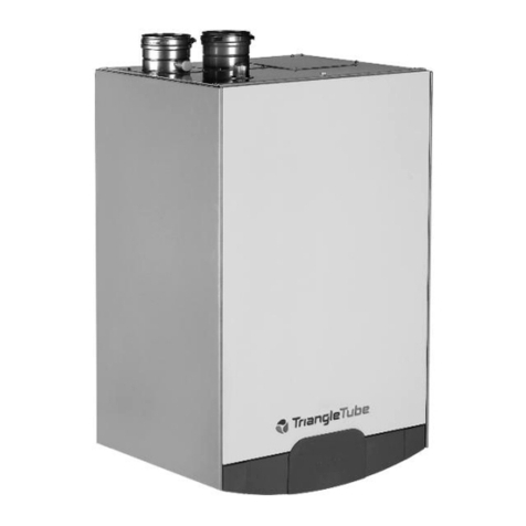
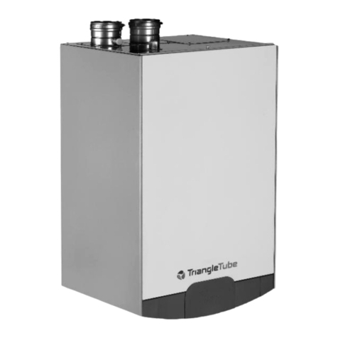
  9. TriangleTube CHALLENGER CC 85 User manual

TriangleTube CHALLENGER CC 85 User manual

CHALLENGER
Prop ne to N tur l G s Instructions
1
Kit Part Number: CCRKIT02
Kit Includes:
- Rating Label
- (3) Natural Gas Orifices
- T-15 Torx Wrench
Recommended Tools:
- Phillips-Head Screwdriver
- Standard Adjustable Wrenches
- Calibrated Combustion Analyzer
Indic tes potenti lly h z rdous situ tion which, if
ignored, c n result in serious injury or subst nti l
property d m ge.
Indic tes speci l instructions on inst ll tion, oper tion
or m inten nce, which re import nt to equipment but
not rel ted to person l injury h z rds.
WARNING NOTICE
This conversion kit sh ll be inst lled by qu lified ser-
vice gency in ccord nce with the m nuf cturer’s
instructions nd ll pplic ble codes nd requirements
of the uthority h ving jurisdiction. If the inform tion in
these instructions is not followed ex ctly, fire, n explo-
sion or production of c rbon monoxide m y result c us-
ing property d m ge, person l injury or loss of life. The
qu lified service gency is responsible for the proper
inst ll tion of this kit. This inst ll tion is not proper nd
complete until the oper tion of the converted ppli nce
is checked s specified in the m nuf cturer’s instruc-
tions supplied with the kit.
F ilure to follow instructions below c n result in severe
person l injury or d m ge if ignored:
- Instructions re for qu lified inst ller / service
technici n.
- Re d ll instructions before proceeding.
- Follow instructions in the proper order.
The g s supply sh ll be shut off prior to disconnecting
the electric l power, before proceeding with the conver-
sion.
For your s fety, turn off electric l power supply t ser-
vice p nel nd llow ppli nce to cool before proceeding.
F ilure to do so c n c use severe person l injury or
de th.
Upon completion of the conversion from Prop ne to
N tur l G s, ffix the new r ting l bel included in the kit
to the ppli nce just below the existing r ting l bel on
the right side j cket p nel. DO NOT ffix the new l bel
over the existing r ting l bel. Remove prop ne conver-
sion l beling from the g s v lve. Complete the
Inst ll tion Record by recording the combustion re ding
in the CHALLENGER Inst ll tion nd M inten nce
M nu l.
WARNING
WARNING
CAUTIONWARNING
NOTICE
Inst ll tion of the N tur l G s Orifice
1. Close the manual gas shut off valve to the appli-
ance.
2. Turn off the electrical power supply to the appliance.
3. Remove the front panel by flipping down the control
panel and loosening the two Phillips head mounting
screw(s) at the control panel. Pull bottom of front
panel forward to remove.
4. Disconnect the gas piping inside the CHALLENGER
enclosure at the brass union located above the gas
valve, and rotate piping towards the back of appli-
ance, see Fig. 1.
The g s orifice is inst lled in O-ring g sket. This O-ring
g sket must be reinst lled when ever the g s orifice is
ch nged. Use c re not to d m ge the O-ring g sket.
5. Separate the O-ring gasket from the propane gas
orifice and insert the appropriate brass natural ori-
fice from Table 1 into the O-ring gasket.
The CHALLENGER ppli nces cont in prop ne g s ori-
fice. This orifice must be removed prior to the inst ll -
tion of the n tur l g s orifice.
F ilure to ret in the O-ring g sket on the g s orifice will
c use n improper se l between the g s v lve nd the
union resulting in potenti l risk of g s le k. Ensure
unions t top nd bottom of g s v lve re tight. Any
potenti l g s le k ge m y result in de th, serious injury
or subst nti l property d m ge.
Ensure the proper orifice for n tur l g s is inst lled s given
in T ble 1. F ilure to comply will ffect input r te nd com-
bustion efficiency of the ppli nce which m y result in
de th, serious injury or subst nti l property d m ge.
6. nstall proper natural gas orifice/O-ring gasket
assembly on the top of the gas valve.
7. Reconnect the gas piping on top of gas valve and
tighten the brass union connections at the gas
valve.
WARNING
NOTICE
NOTICE
WARNING
CHALLENGER
Prop ne to N tur l G s Instructions
2
T ble 1: N tur l G s Orifice
Gas Orifice
O-Ring Gasket
Gas
Piping
Union
Nut
Gas
Valve
Fig. 1: CHALLENGER G s V lve/Orifice
Assembly
CHALLENGER
MODEL
Propane Gas
Orifice Size
Orifice
Marking
CC50s 0.217” [5.50 ] 550
CC85 or
CC85s 0.256” [6.50 ] 650
CC105 or
CC105s 0.256” [6.50 ] 650
CC125, CC125c or
CC125s 0.285” [7.25 ] 725
CC125H or
CC125Hs 0.217” [5.50 ] 550
CC150s 0.285” [7.25 ] 725
CHALLENGER
Prop ne to N tur l G s Instructions
3
8. Open the manual gas shut off valve. Before placing
the CHALLENGER back into operation check and
test all gas connections for leaks. Repair leaks if
found.
Do not check for g s le ks with n open fl me. Use bub-
ble test. F ilure to check for g s le ks c n c use severe
person l injury, de th or subst nti l property d m ge.
Inspect Ignition Electrode
Prior to inspecting the ignition electrode, ensure ll electri-
c l power supply to the ppli nce is turned off to void elec-
tric l shock.
1. Remove the ignition electrode using the T-15 Torx
wrench.
2. Remove any white oxides accumulated on the elec-
trode using fine grit sandpaper or steel wool. f the
electrode does not clean to a satisfactory condition,
replace the ignitor.
3. Check ignitor to Fig. 2
4. When replacing the ignition electrode, ensure the
gasket is in good condition and correctly positioned,
replace gasket if necessary.
Check Inlet G s Supply Pressure
1. Turn on the electrical power supply to the CHAL-
LENGER.
2. Check the inlet gas supply pressure to the CHAL-
LENGER at the gas valve (see Figs. 3 and 4 on page
5). Ensure a minimum pressure of 5” w.c [13 mbar]
during flow conditions with all gas appliances firing
including the CHALLENGER and a maximum pres-
sure of 13” w.c [32 mbar] during non-flow conditions
with all gas appliances off including the CHAL-
LENGER.
Combustion Test nd Adjustments
1. The installer must perform a complete combustion
check to ensure the following combustion levels are
met at high and low input firing rates and the burner
is operating at optimum conditions for propane gas.
The combustion testing nd djustments must be performed
only by qu lified inst ller, service gency or the g s suppli-
er. All combustion me surements must be performed with
c libr ted equipment to ensure proper re dings nd ccur -
cy.
WARNING
WARNING
WARNING
Spark gap approximately. 0.18”
1.06” -1.12”
0.12 [ 3 mm]
0.12 [3 mm]
0.43 [11 mm]
[27 mm - 29 mm]
[5 mm]
1.75 [44 mm]
1.18 [30 mm]
(
4
5
.
0
0
)
Fig. 2: Igniter Dimensions
CHALLENGER
Prop ne to N tur l G s Instructions
4
T ble 2: Recommended Combustion Levels
F ilure to perform complete combustion test t both
high nd low input r tes m y result in incomplete combus-
tion nd the production of c rbon monoxide, which c n
c use severe person l injury, de th or subst nti l property
d m ge.
2. Manually place the appliance into high fire mode by
pressing both the service button “ ” with “+” but-
ton simultaneously on the control panel display two
times.
The control p nel will displ y H followed by the current
ppli nce temper ture when pl ced into high fire test
mode.
The THROTTLE SCREW on the CHALLENGER’s g s v lve
works opposite th n the PRESTIGE. If you turn the
CHALLENGER’s THROTTLE SCREW clockwise you incre se
the input, CO2nd CO of the ppli nce. EXERCISE CARE!
3. f the combustion levels during high fire are outside
the recommended combustion settings, adjust the
THROTTLE SCREW (see Figs. 3 and 4 on page 5)
using a T15 Torx wrench as follows:
Counter-clockwise adjustment of the THROTTLE
SCREW at High Fire:
O2 increases and CO2 decreases
Clockwise adjustment of the THROTTLE SCREW
at High Fire:
O2 decreases and CO2 increases
4. Once the combustion level is set and recorded at
high fire, manually place the appliance into low fire
mode by pressing the service button “ ” with “-”
button simultaneously on the control display once.
The control p nel will displ y L followed by the current
ppli nce temper ture when pl ced into low fire test
mode.
5. f the combustion levels during low fire are not within
0.0 to 0.4% CO2 lower than the combustion level
measured at high fire, remove the offset pressure
cover screw and adjust the OFFSET SCREW (see
Figs. 3 and 4 on page 5) using a T15 Torx wrench
as follows:
The OFFSET SCREW djustment on the CHALLENGER’S g s
v lve is very sensitive. A sm ll djustment will h ve sig-
nific nt effect.
Counter-clockwise adjustment of the OFFSET
SCREW at Low Fire:
O2increases and CO2 decreases
Clockwise adjustment of the OFFSET SCREW at
Low Fire:
O2decreases and CO2 increases
WARNING
NOTICE
WARNING
NOTICE
WARNING
Combustion Levels Natural Gas Propane Gas
High Fire
DOOR OFF*
CO2Range 9% to 10.1% 10.5% to 11.1%
CO2Target 9.0% 10.8%
O2Range 3.0% - 5.0% 4.1% - 5.0%
O2Target 5.0% 4.5%
Low Fire
CO2Range 0% - 0.4% < H.F
9.0% min.
0% - 0.4% < H.F
10.5% min.
O2Range 0% - 0.6% > H.F
5.0% max.
0% - 0.6% > H.F
5.0% max.
CO Max. 100 ppm 150 ppm
* Door On can raise the maximum allowable CO2by
0.4 or lower the minimum allowable 02by 0.6.
CHALLENGER
Prop ne to N tur l G s Instructions
6. Confirm the combustion levels at both high fire and
low fire meet the requirements listed in Table 2 on
page 4.
7. Press the “+” and “-” button simultaneously to cancel
high or low fire mode. Test mode will time out in
approximately 10 minutes.
8. Replace offset cover screw.
9. Check the flame pattern through the inspection port
on the left side of the heat exchanger. The flame
should be blue and stable and should be the length
of the burner.
10. Replace the front jacket panel and secure with the
two Phillips head mounting screws at the control
panel.
Me sure Input
1. Ensure the appliance is firing at maximum firing
rate. To manually place the appliance into high fire
mode, press both the service button “ ” with “+”
button simultaneously on the control panel display
two times.
The control p nel will displ y H followed by the current
ppli nce temper ture when pl ced into high fire test
mode.
2. Operate the appliance for approximately 5 minutes.
3. Turn off all gas appliances within the building,
except the CHALLENGER.
4. At the gas meter, record the time required to use
one cubic foot of gas.
5. Calculate Natural gas input using the following
equation:
3600 x 1000/number of second recorded for one
cubic foot of gas = BTU/H.
6. The BTU/H calculated should approximate the input
rating listed on the appliance.
7. Press the “+” and “-” button simultaneously to cancel
high or low fire mode. Test mode will time out in
approximately 10 minutes.
8. Return appliance back to service.
NOTICE
Offset Pressure
Cover Screw
Throttle Screw
Offset Pressure Port
Inlet Gas Supply
Pressure Port
Flow direction
Fig. 3: Origin l G s V lve
Fig. 4: Upd ted G s V lve
2010-42 CHALLENGER Propane to Natural nst.
Date: 10/6/2016

Other manuals for CHALLENGER CC 85

3

This manual suits for next models

10

Other TriangleTube Boiler manuals

TriangleTube Prestige Excellence Instruction Manual

TriangleTube

TriangleTube Prestige Excellence Instruction Manual

TriangleTube instinct SOLO 110 User guide

TriangleTube

TriangleTube instinct SOLO 110 User guide

TriangleTube Instinct  SOLO 155 Instruction Manual

TriangleTube

TriangleTube Instinct SOLO 155 Instruction Manual

TriangleTube prestige Service manual

TriangleTube

TriangleTube prestige Service manual

TriangleTube Prestige Solo 60 Manual

TriangleTube

TriangleTube Prestige Solo 60 Manual

TriangleTube Instinct Series Guide

TriangleTube

TriangleTube Instinct Series Guide

TriangleTube Prestige Solo 60 User manual

TriangleTube

TriangleTube Prestige Solo 60 User manual

TriangleTube Prestige Solo Manual

TriangleTube

TriangleTube Prestige Solo Manual

TriangleTube Challenger Guide

TriangleTube

TriangleTube Challenger Guide

TriangleTube prestige User manual

TriangleTube

TriangleTube prestige User manual

TriangleTube prestige Use and maintenance manual

TriangleTube

TriangleTube prestige Use and maintenance manual

TriangleTube Challenger Manual

TriangleTube

TriangleTube Challenger Manual

TriangleTube Prestige Excellence Manual

TriangleTube

TriangleTube Prestige Excellence Manual

TriangleTube Instinct FSB SOLO 110 Instruction Manual

TriangleTube

TriangleTube Instinct FSB SOLO 110 Instruction Manual

TriangleTube instinct SOLO 110 Instruction Manual

TriangleTube

TriangleTube instinct SOLO 110 Instruction Manual

TriangleTube Prestige PARKIT101 User manual

TriangleTube

TriangleTube Prestige PARKIT101 User manual

TriangleTube Prestige Solo 399 User manual
TriangleTube

TriangleTube Prestige Solo 399 User manual

TriangleTube Challenger Manual

TriangleTube

TriangleTube Challenger Manual

TriangleTube Prestige Excellence Instruction Manual

TriangleTube

TriangleTube Prestige Excellence Instruction Manual

TriangleTube CHALLENGER CC 85 Manual

TriangleTube

TriangleTube CHALLENGER CC 85 Manual

TriangleTube Instinct User manual

TriangleTube

TriangleTube Instinct User manual

TriangleTube PRESTIGE Series Guide

TriangleTube

TriangleTube PRESTIGE Series Guide

TriangleTube PRESTIGE Solo PA 110 User manual

TriangleTube

TriangleTube PRESTIGE Solo PA 110 User manual

TriangleTube Prestige Solo 175 User manual
TriangleTube

TriangleTube Prestige Solo 175 User manual

Popular Boiler manuals by other brands

Gialix 36 MA installer and user manual

Gialix

Gialix 36 MA installer and user manual

TERMET COMBI BOILER ECOCONDENS CRYSTAL PLUS-50 instruction manual

TERMET

TERMET COMBI BOILER ECOCONDENS CRYSTAL PLUS-50 instruction manual

ferolli KONA 12 Instructions for use

ferolli

ferolli KONA 12 Instructions for use

Sime MERIDIAN HE 30 C Installation and servicing instructions

Sime

Sime MERIDIAN HE 30 C Installation and servicing instructions

Unical IDEA AB 24 Installation and Servicing Manual

Unical

Unical IDEA AB 24 Installation and Servicing Manual

Worcester Greenstar 4000 Installation and maintenance instructions

Worcester

Worcester Greenstar 4000 Installation and maintenance instructions

Sime 1R OF Series manual

Sime

Sime 1R OF Series manual

Slant/Fin VICTORY II VHS Series Specifications

Slant/Fin

Slant/Fin VICTORY II VHS Series Specifications

ECOFOREST Vap 5-20 Installation and maintenance manual

ECOFOREST

ECOFOREST Vap 5-20 Installation and maintenance manual

Worcester GREENSTAR 24i junior User instructions & customer care guide

Worcester

Worcester GREENSTAR 24i junior User instructions & customer care guide

Unical TRIOPREX N Series INSTALLATION, USE AND SERVICING INSTRUCTION

Unical

Unical TRIOPREX N Series INSTALLATION, USE AND SERVICING INSTRUCTION

Viessmann B2TB004 installation instructions

Viessmann

Viessmann B2TB004 installation instructions

Protherm Provitherm 28 KTV User, installation and servicing instructions

Protherm

Protherm Provitherm 28 KTV User, installation and servicing instructions

HTP UFT-100W User's information manual

HTP

HTP UFT-100W User's information manual

Dunkirk PSB-3D Installation, operation & maintenance manual

Dunkirk

Dunkirk PSB-3D Installation, operation & maintenance manual

Viessmann VITODENS Technical guide

Viessmann

Viessmann VITODENS Technical guide

RVR Energy Technology Immergas Zeus Mini Instruction booklet

RVR Energy Technology

RVR Energy Technology Immergas Zeus Mini Instruction booklet

Fröling S3 Turbo installation instructions

Fröling

Fröling S3 Turbo installation instructions

manuals.online logo
manuals.online logoBrands
  • About & Mission
  • Contact us
  • Privacy Policy
  • Terms and Conditions

Copyright 2025 Manuals.Online. All Rights Reserved.