3
2955 11 2022
-
RCT 20E, 21E, 22E, 23E & REMOTE RECEIVER
Sleipner Motor AS
P.O. Box 519, Arne Svendsensgt. 6-8
N-1612 Fredrikstad, Norway
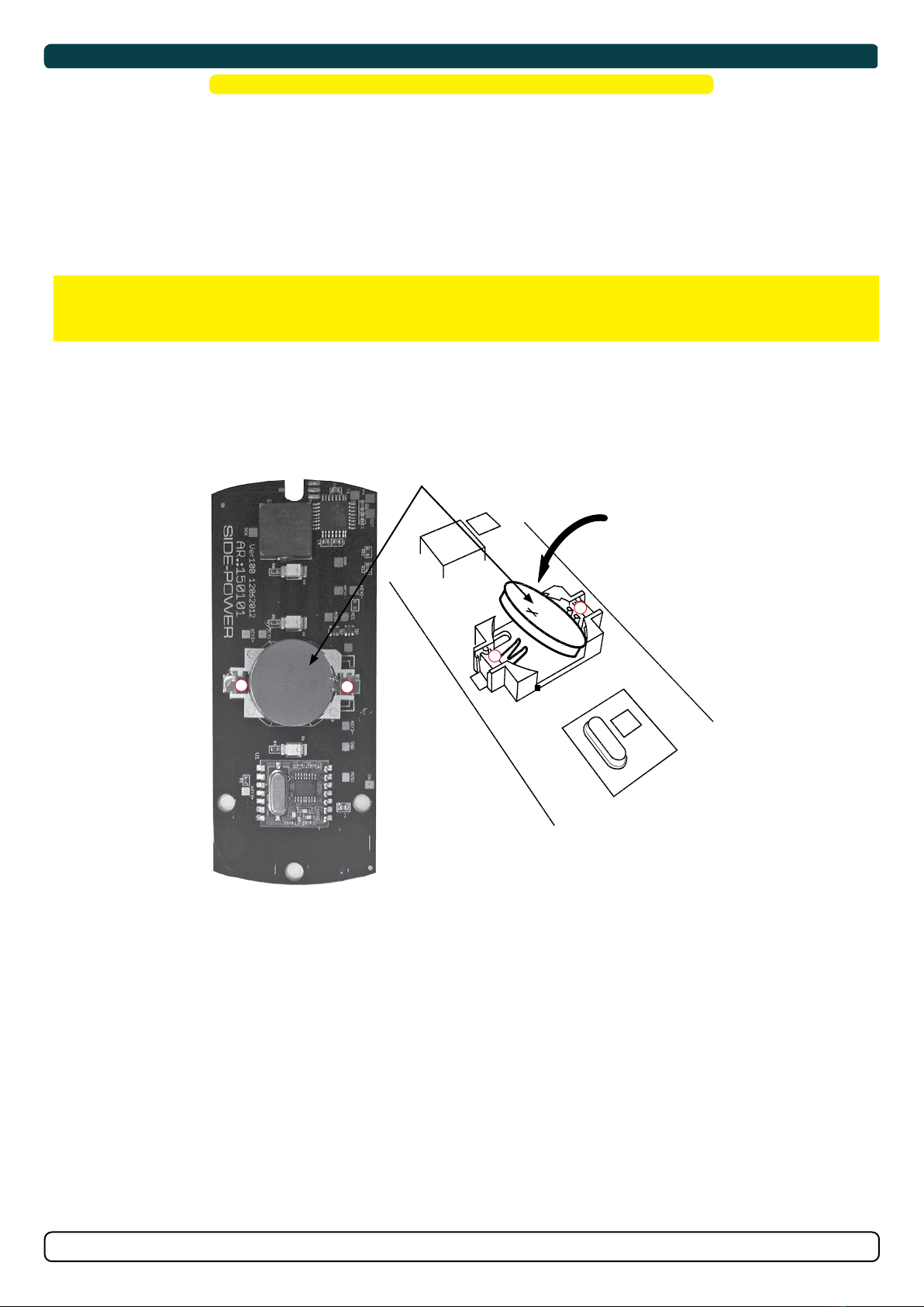
MC_0020
Contents
MC_0418
• Always turn the control device off when the thruster is not in use or when leaving the boat.
• When leaving the boat always turn off the main power switch for the thruster.
• Never use thrusters out of water.
• If the thruster stops giving thrust while running, there is possibly a problem in the drive system. You must immediately stop running the thruster
and turn it off. Running the thruster for more than a few seconds without resistance from the propeller can cause serious damage to the thruster.
• If two panels are operated with conflicting directions at the same time the thruster will not run. If both are operated in the same direction, the
thruster will run in this direction.
• If you notice any faults with the thruster switch it off to avoid further damage.
• The primary purpose of the thruster is to manoeuvre or dock the vessel. Forward or reverse speed must not exceed 4 knots when operated.
For the operation of thrusters
Never use thrusters when close to objects, persons or animals in the water. The thruster will draw objects into the tunnel and the rotating
propellers. This will cause serious injuries and damage the thruster.
Always turn the main power switch off before touching any part of the thruster. An incidental start while touching moving parts can cause
serious injuries.
It is the owner, captains or other responsible parties full responsibility to assess the risk of any unexpected incidents on the vessel.
If the thruster stops giving thrust for some reason while manoeuvring you must have considered a plan on how to avoid damage to persons or
other objects.
MC_0307
For Windlass systems
• Keep your distance to the windlass, the rope, anchor and anchor brackets during operation
• While operating the anchor maintain observation of the rope or chain during handling.
• Ensure anyone using the windlass knows how to operate it.
• Be aware when the anchor are raised as it can bring unwanted debris up from the bottom, potentially damaging your boat. (NB: If the windlass is
straining as the anchor is raised, stop for a few seconds and let the boat pic up momentum before continuing the raise.)
• If the anchor is stuck, release some rope/chain and attach it to a cleat before using the boat to pull the anchor free. The windlass is not designed
for loads beyond the specifi ed pull capabilities.
• The anchor MUST ALWAYS be secured to the boat while under way. Use the security line or other means to prevent unintentional anchor drop.
• Turn off the power to the windlass when not in use.
• Children must not operate the windlass.
• Careless use can cause damage or injury!
• Keep the engine running during windlass operation to ensure good battery capacity.
• Sleipner Motor AS is not responsible for damage or injury caused by the use of our windlass systems.
• While dropping anchor, do not push the “UP” button until the anchor is resting at the seabed.
• Always turn the control device off when the thruster is not in use.
Never use a windlass close to somebody in the water, an unexpected drop of the anchor can cause serious injuries.
It is the owner/ captain/ other responsible parties full responsibility to assess the risk of any unexpected incidents on the vessel.
Failure to follow the considerations and precautions can cause serious injury,
damage and will render all warranties given by Sleipner Motor as VOID.
MC_0411
MC_0444
General Operation Considerations and Precautions Guidelines
For the operation of remote controls
• To reduce risk of dropping the remote transmitter in the water during operation it is recommended to wear the neck strap fastened to the remote
control.
It is recommended that the remote transmitter is stored in a secured location to avoid operation by unintentional personnel and to ensure
availability when operation is required. This could be achieved by mounting the holding bracket in a location on the bridge not easily accessible
to children and other unauthorized personnel.
MC_0443
Sleipner Motor AS
P.O. Box 519, Arne Svendsensgt. 6-8
N-1612 Fredrikstad, Norway