Sleipner RCT-20E User manual

User Manual
SLEIPNER AS
P.O. Box 519
N-1612 Fredrikstad
Norway
www.sleipnergroup.com
DOCUMENT ID:
REVISION:
DATE:
LANGUAGE:
To download your language go to www.sleipnergroup.com
2955
10
Keep this
manual onboard!
2021
D
OCUMENT ID:
29
55
Including Installation For Remote Controls
RCT-20E, RCT-21E, RCT-22E, RCT-23-E
RCR-2E, RCRS-2E
EN
U M
I M

22955 10 2021
-
RCT20E,21E,22E,23E&REMOTERECEIVER
DECLARATION OF CONFORMITY
Sleipner Motor AS
P.O. Box 519, Arne Svendsensgt. 6-8
N-1612 Fredrikstad, Norway
Declare that this product with accompanying standard control systems complies with the
essential health and safety requirements according to:
DIRECTIVE 2013/53/EU
DIRECTIVE 2014/30/EU
DIRECTIVE 2014/35/EU
MC_0020
Considerations and Precautions.............................................. 3
Signals Considerations and Precautions ................................ 3
Installation Manual
Remote Control Kits ................................................................... 4
Panel Layout & Functions .......................................................... 5
43³............................................................. 6
3I,43³................................................. 6
Receiver Installation .................................................................. 7
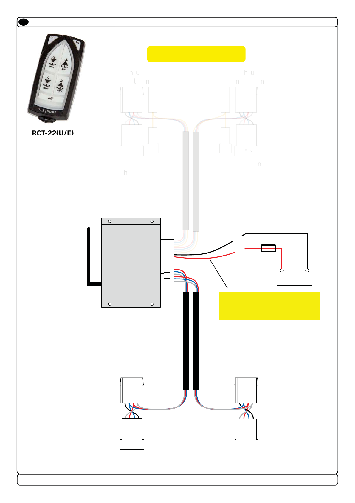
Technical Wiring Diagram .................................................. 8 - 11
Output Signals Diagram........................................................... 12
Programming Additional Transmitters/ Remote Controls...... 13
S-Link Receiver Installation .................................................... 14
Technical Wiring Diagram........................................................ 15
S-Link Receiver Installation .................................................... 16
Transmitter Installation and Battery Replacement................ 17
User Manual
Important Thruster User Considerations and Precautions .... 18
Thruster Operation ........................................................... 19 - 20
Transmitter LED Operation and Alarm Indication .................. 21
Receiver LED Indicator ............................................................ 21
S-Link Transmitter LED Operation and Alarm Indication....... 21
S-Link Receiver LED Indicator................................................. 21
Service and Support....................................................... 22
Product Spare Parts and Additional Resources................ 22
Warranty statement ....................................................... 22
Patents.......................................................................... 22
Contents
EN
Products
SM126344 | RCT-23E - Fjernkontrollsend.dbl.vins/thr
SM126317 | RC-21E - Fjernkontrollsett baug/vinsj
SM126428 | RC-23E - Fjernkontroll dbl.vinsj/thrust
SM126315 | RCT-21E - Fjernkontrollsender baug/vinsj
SM126335 | RC-20E - Fjernkontrollsett baug og hekk
SM126327 | RC-22E - Fjernkontrollsett dbl. vinsj
SM126251 | RCR-2E - Fjernkontrollmottaker
SM904984 | RCT-20E - Fjernkontrollsender baug/hekk
SM126321 | RCT-22E - Fjernkontrollsender dbl. vinsj

3
2955 10 2021
-
RCT20E,21E,22E,23E&REMOTERECEIVER
MC_0105
Considerations and Precautions
EN
IMPORTANT
If installing S-link products DO NOT connect any other control equipment to the S-link controlled products except Sleipner original S-link
products or via a Sleipner supplied interface product made for interfacing with other controls. Any attempt to directly control or at all connect
into the S-link control system without the designated and approved interface will render all warranties and responsibilities for the complete
line of Sleipner products connected void and null. If you are interfacing by agreement with Sleipner and through a designated Sleipner
Q3³
necessary.
It is the installers responsibility
73l³flg
international or special national regulations. Instructions in this guide cannot be guaranteed to comply with global electric/
l³N
&l³N
Before installation, it is important that the installer reads this guide to ensure necessary acquaintance with the product.
4/.,9Q3-!3f3g
Ql³N
4l³
installation. (NB: These instructions are only general instruction. If you are not skilled to do this work, please contact professional
installers for assistance.)
All electrical work must be done by a licensed professional.
Faulty installation of Sleipner products will render all warranty given by Sleipner Motor AS void. MC_0038
MC_0211
Signals Considerations and Precautions
EN
IMPORTANT
Sleipner has developed remote controls with approval in the EU and US markets. However, it is the Importers responsibility to comply with all
restrictions and legislation on radio signals in the country to which it is imported.

42955 10 2021
-
RCT20E,21E,22E,23E&REMOTERECEIVER
Remote Control Kits
EN MC_0228
Remote control kit RC-20U/E consists of:
- Receiver: Part no. RCR-2U/E
I 4fN"gP0N2#4I?;5l%
- Holding bracket for transmitter unit: Part no. RC-HOLDER
Remote control kit RC-21U/E consists of:
- Receiver: Part no. RCR-2U/E
I 4fN"gP0N2#4I?>5l%
- Holding bracket for transmitter unit: Part no. RC-HOLDER
Remote control kit RC-22U consists of:
- Receiver: Part no. RCR-2U/E
I 4fN"gP0N2#4I??5l%
- Holding bracket for transmitter unit: Part no. RC-HOLDER
Remote control kit RC-23U consists of:
- Receiver: Part no. RCR-2U/E
I 4fN"gP0N2#4I?@5l%
- Holding bracket for transmitter unit: Part no. RC-HOLDER
Remote control kit RCS-20U/E consists of:
- Receiver: Part no. RCRS-2U/E
I 4fN"gP0N2#4I?;5l%
- Holding bracket for transmitter unit: Part no. RC-HOLDER
{5&53!³
{%&%³
{5&53!³
{%&%³
{5&53!³
{%&%³
{5&53!³
{%&%³
{5&53!³
{%&%³

5
2955 10 2021
-
RCT20E,21E,22E,23E&REMOTERECEIVER
Remote Layout & Functions
EN MC_0175
Bow directional control for
the thruster.
Stern directional control for
the thruster.
Directional control
for the thruster.
Windlass
retract
Windlass release
Bow windlass
release
Bow windlass
release
Stern windlass
release
Bow windlass
retract
Bow windlass
retract
Stern windlass
retract
Stern windlass
retract
Bow directional
control for the
thruster.
Stern directional
control for the
thruster.
Pair Button
Pair Button
Dual Bow and stern
directional control for
the thruster.
Dual Bow and stern
directional control for
the thruster.
{5&53!³
{%&%³
{5&53!³
{%&%³
{5&53!³
{%&%³
{5&53!³
{%&%³
{5&53!³
{%&%³
{5&53!³
{%&%³
RCT-20(U/E)
RCRS-2(U/E) RCR-2(U/E)
RCT-22(U/E)
Receiver
Remote Transmitter
RCT-21(U/E)
RCT-23(U/E)
Turn ‘ON’ the
remote radio
Turn ‘ON’ the
remote radio
Turn ‘ON’ the
remote radio
Turn ‘ON’ the
remote radio
Turn ‘OFF’ the
remote radio
Turn ‘OFF’ the
remote radio
Turn ‘OFF’ the
remote radio
Turn ‘OFF’ the
remote radio
Stern windlass
release
&3I,³

62955 10 2021
-
RCT20E,21E,22E,23E&REMOTERECEIVER
MG_0191
112
145
118
4
7
110
15
38
107
21
97
57
45
83
36
47
136
Ø 4.5
Ø 3
Ø 3
4l2I43³
3I,4l2I43³
EN
EN
MC_0176
MC_0176
Transmitter Receiver
Power feed >@6fP#2?;@?g 12V or 24V power source
&f-( g ECE-( ECE-(
RF-power <10mW <10mW
Operation temp. -10°C / +55°C -10°C / +55°C
(7$fg 107x47x21 83x136x36
7fg 60 275
Voltage 8-30V
Standby power <300mW
Load, max 4A
Transmitter Receiver
Power feed >@6fP#2?;@?g 12V or 24V power source
&f-( g ECE-( ECE-(
Operation temp. -10°C / +55°C -10°C / +55°C
(7$fg 107x47x21 110x35x35
7fg 60 170
Voltage 8-30V
Operating range 30m under normal operating conditions

7
2955 10 2021
-
RCT20E,21E,22E,23E&REMOTERECEIVER
Receiver Installation
EN
)>f@gQNN
navigation instruments, radio communication devices, electric motors and generators.
)>f@gN
• Install the receiver outside of shielded areas for radio signals, i.e. boxes made of metals or other material with shielding properties.
)QNf4NgN
• Mount the receiver using the four holes.
4³B!
N4l³
negative lead there.
• Connect the supplied wiring harnesses to the receiver unit according to the wiring diagram. Connect thrusters and windlasses to the appropriate
connectors according to the diagram.
• For use with other windlass brands, connections must be determined by the installer according to the out put signals diagram.
NB: Max. load on the windlass signal output is 4A! If the windlass requires more than 4A, use extra control relay.
MC_0177
!Please refer to the graphic for special considerations relating to your model !
IMPORTANT
Remote receiver power supply negative lead must be connected to the thrusters’ negative lead. Bow and stern thruster must have a common
negative. Power to the thrusters must be switched off during installation!
MG_0193
Mount the receiver
by using the 4 holes

82955 10 2021
-
RCT20E,21E,22E,23E&REMOTERECEIVER
MG_0406
Technical Wiring Diagram
EN
RED
BLACK
BOW STERN
S
T
E
R
N
B
OW
To Bow
Thruster
To Stern
Thruster
To Thruster
Control Panel
T
o
W
i
n
d
l
a
ss
C
o
n
t
r
o
l
P
a
n
el
To Thruster
Control Panel
T
o
W
i
n
d
l
a
ss
C
o
n
t
r
o
l
P
a
n
e
l
T
o
B
o
w
W
i
n
d
l
a
s
s
T
o
S
t
e
rn
W
i
n
d
l
a
s
s
Battery12/24V
+ -
FUSE
5A
IMPORTANT
Cables/wires must be cable tied well.
IMPORTANT
Power cables must be connected to the
battery as shown. Remaining wires must
be cable tied well.
RCT-20(U/E)
R
C
T
-20(U/E)
T
T

9
2955 10 2021
-
RCT20E,21E,22E,23E&REMOTERECEIVER
MG_0407
Technical Wiring Diagram
EN
RED
BLACK
BOW
S
T
E
R
N
STERN
BO
W
To Bow
Thruster
T
o
S
t
e
r
n
T
h
r
u
s
t
e
r
To Thruster
Control Panel
T
o
W
i
n
d
l
a
ss
C
o
n
t
r
o
l
P
a
n
el
T
o
T
h
r
u
s
t
e
r
C
o
n
t
r
o
l
P
a
n
e
l
To Windlass
Control Panel
T
o
B
o
w
W
i
n
d
l
a
s
s
To Stern
Windlass
Battery12/24V
+ -
FUSE
5A
IMPORTANT
Cables/wires must be cable tied well.
IMPORTANT
Power cables must be connected to the
battery as shown. Remaining wires must
be cable tied well.
RCT-21(U/E)
EN
R
C
T
-21(U/E)
TT

10 2955 10 2021
-
RCT20E,21E,22E,23E&REMOTERECEIVER
MG_0408
Technical Wiring Diagram
EN
RED
BLACK
B
OW
S
T
E
R
N
STERN
BOW
T
o
B
o
w
T
h
ru
s
t
e
r
T
o
S
t
e
r
n
T
hrus
t
e
r
T
o
T
h
r
u
s
t
e
r
C
o
n
t
r
o
l
P
a
n
e
l
To Windlass
Control Panel
T
o
T
h
r
u
s
t
e
r
C
o
n
t
r
o
l
P
a
n
e
l
To Windlass
Control Panel
To Bow
Windlass
To Stern
Windlass
Battery12/24V
+ -
FUSE
5A
IMPORTANT
Cables/wires must be cable tied well.
IMPORTANT
Power cables must be connected to the
battery as shown. Remaining wires must
be cable tied well.
RCT-22(U/E)
EN
C
R
C
T
-2
2(
U/
E)
T
T

11
2955 10 2021
-
RCT20E,21E,22E,23E&REMOTERECEIVER
MG_0195
Technical Wiring Diagram
EN
RED
BLACK
BOW STERN
STERN
BOW
To Bow
Thruster
To Stern
Thruster
To Thruster
Control Panel
To Windlass
Control Panel
To Thruster
Control Panel
To Windlass
Control Panel
To Bow
Windlass
To Stern
Windlass
Battery12/24V
+ -
FUSE
5A
IMPORTANT
Cables/wires must be cable tied well.
IMPORTANT
Power cables must be connected to the
battery as shown. Remaining wires must
be cable tied well.
RCT-23(U/E)
EN
R
C
T
-23(U/E)
T
T

12 2955 10 2021
-
RCT20E,21E,22E,23E&REMOTERECEIVER
MG_0196
Output Signals Diagram
EN
Thruster Bow
RED - Thruster Positive
BLUE - Thruster STBD
RED - Common
BLUE - Windlass IN
GREY - Windlass OUT
RED - Common
BLUE - Windlass IN
GREY - Windlass OUT
GREY - Thruster PORT
YELLOW - Automatic Main switch Enable
RED - Thruster Positive
BLUE - Thruster STBD
GREY - Thruster PORT
YELLOW - Automatic Main switch Enable
Thruster Stern
Windlass Bow
Windlass Stern

13
2955 10 2021
-
RCT20E,21E,22E,23E&REMOTERECEIVER
Programming Additional Transmitters/ Remote Controls
EN
The original transmitter and receiver have the same factory pre-set code so that no programming is necessary. When additional transmitters
remote controls are to be used, the additional transmitters/remote controls have to be paired with the receiver.
>N"f',%$gN
?N00"fgN",%$Y
simultaneously.
3. Within 10s after the receiver pair button is pushed, set the transmitter in pairing mode by holding the off button and pressing both “ON” buttons
at the same time, all the transmitter LED’s turn on indicating that it is set in pairing mode. When a pairing signal is received from the receiver the
transmitter LED’s while turn off and the system is ready to be used. If no pairing signal received within 10s the transmitter will leave the pairing
mode.
4. Additional transmitters/remote controls must be programmed according to step 2-3. You can pair up to 4 transmitters/remote controls.
5. To clear all transmitters/remote controls paired with the receiver hold the pair button on the receiver for approximately 10s until the red and
green led stop blinking. When the LED’s stop blinking release the pair button, the green led will again start to blink when the receiver has
completed the reset process. The receiver is then ready to pair with up to four transmitters/remote controls. Take time to practice operation in
open water to become familiar with the thruster and to avoid damages to your boat or people.
MC_0181
!Please refer to the graphic for special considerations relating to your model !
MG_0197
Pair Button Pair Button
Pair Button
Pair Button

14 2955 10 2021
-
RCT20E,21E,22E,23E&REMOTERECEIVER
S-Link Receiver Installation
EN
)>f@gQNN
navigation instruments, radio communication devices, electric motors and generators.
)>f@gN
• Install the receiver outside of shielded areas for radio signals, i.e. boxes made of metals or other material with shielding properties.
)QNf4NgN
• Mount the receiver using the four holes.
• The receiver is powered by the S-link cable.
• Connect the supplied wiring harnesses to the receiver unit according to the wiring diagram. Connect thrusters and windlasses to the appropriate
connectors according to the diagram.
• For use with other windlass brands, connections must be determined by the installer according to the out put signals diagram.
MC_0183
!Please refer to the graphic for special considerations relating to your model !
MG_0193
Mount the receiver
by using the 4 holes

15
2955 10 2021
-
RCT20E,21E,22E,23E&REMOTERECEIVER
MG_0195
Technical Wiring Diagram
EN
+12/24V -
5A
S-link on/off
switch
red
yellow
black
12/24V12/24V
Stern thruster
battery
Bow thruster
battery
Bow thruster
(SEP model)
Stern thruster
(SEP model)
-
black
+
red
B+
-
black +
red
B+ Fixed multicable 5m
Fixed multicable 5m
5A
+12/24 5A +12/24
PPC
PPC
Proportional
Power Controller
Proportional
Power Controller
PJC 212
Proportional
Joystick
Controlpanel
Station 1
Automatic Main Switch
8977 12 / 8977 24
or
Manual main switch
w/ANL fuse
Automatic Main Switch
8977 12 / 8977 24
or
Manual main switch
w/ANL fuse
S-link control system End terminator
End terminator
Proportional
Joystick
Controlpanel
Station 2
PJC 212
Observe PPC battery
terminal polarity !
S-link supply
S-link remote receiver
RCRS-1E

16 2955 10 2021
-
RCT20E,21E,22E,23E&REMOTERECEIVER
MG_0200
Pair Button
Pair Button
Pair Button
Pair Button
Programming Additional Transmitters/ Remote Controls
EN
The original transmitter and receiver have the same factory pre-set code so that no programming is necessary. When additional transmitters
remote controls are to be used, the additional transmitters/remote controls have to be paired with the receiver.
>N"f3I,%$gN
?N00"fgN4,).+l!#4,%$N
3. Within 10s after the receiver pair button is pushed, set the transmitter in pairing mode by holding the off button and pressing both “ON” buttons
at the same time, all the transmitter LED’s turn on indicating that it is set in pairing mode. When a pairing signal is received from the receiver the
transmitter LED’s while turn off and the system is ready to be used. If no pairing signal received within 10s the transmitter will leave the pairing
mode.
4. Additional transmitters must be programmed according to step 2-3. You can pair up to 4 transmitters.
5. To clear all transmitters paired with the receiver hold the pair button on the receiver for approximately 10s until the LINK/ACT LED stops blinking.
When the LED stops blinking release the pair button. The receiver is then ready to pair with up to four transmitters.
MC_0202
!Please refer to the graphic for special considerations relating to your model !

17
2955 10 2021
-
RCT20E,21E,22E,23E&REMOTERECEIVER
Transmitter Installation and Battery Replacement
EN
1. Open the transmitter case by removing the 3 torx screws.
2. Remove the battery by inserting a screwdriver or similar between battery and holder at point A and flip the battery out, taking care not to damage
the battery grips at point B.
@N)f4#2?;@?Q@6I"gN%
Qf"gN0!N
4. Close the transmitter. Put the cover back in place, ensure that the rubber seal between remote upper and the lower part is located correctly. Place
@fgN
MC_0178
!Please refer to the graphic for special considerations relating to your model !
IMPORTANT
Before working on the transmitter, deactivate the transmitter and the receiver (push “OFF” on the transmitter(s)) and turn off the power to the
receiver as well as the thruster main switch.
MG_0194
Battery
A
B
AB

18 2955 10 2021
-
RCT20E,21E,22E,23E&REMOTERECEIVER
MC_0179
Important Thruster User Considerations and Precautions
EN
%fg
be turned off in case of serious malfunction.
• Always turn the control device off when the thruster is not in use.
• The maximum continues run time of the electrical thruster is approximately 3 minutes. The electro motor has a built-in thermal cut-off switch that
will shut off the electro-motor if it is overheating and re-engage when it has cooled down. Consider this when planning your manoeuvring.
• As above the thruster will limit its total running time per period. Do not count on the thruster to hold you in a strong current or side wind for extensive
periods. Depending on the surrounding temperatures etc. the thruster will be able to run approximately 10 % of the time.
• Never use thrusters close to objects/ persons or animals in the water, as the thruster will draw objects into the tunnel and contact with the
rotating propellers will cause serious injuries and damage the thruster.
• With the boat on land, only run the thruster for a fraction of a second, as without resistance it will accelerate very fast to a potentially damaging rpm.
• While the thruster is in the air, ensure that the propellers have come to a complete stop before performing a directional change of the thruster, as it
might cause damage to the thruster.
• If the thruster stops giving thrust while the electro-motor is running, there is possibly a problem in the drive system. You must immediately
stop running the thruster and turn it off. Running the electro motor for more than a few seconds without resistance from the propeller can cause
serious damage to the electro motor.
• When leaving the boat always turn off the main power switch for the thruster.
7fgN4N)
QfgN
• Please note the performance of the thruster strongly depends on the voltage available at the electro motor. This voltage will decrease over time
because ageing batteries have reduced capacity. Installing new batteries will bring back the thruster to the original level.
• Ensure only one control is used at the same time, if two panels are operated in opposite directions at the same time the thruster will not run. If
both are operated in the same direction, the thruster will run in this direction.
• If the thruster is not performing or functioning as usual, the cause must be found and corrected as soon as possible to avoid causing any other or
further damage to the equipment. You must also turn off the main battery switch immediately in case the problem is of electric origin.
• It is the owner/ captain/ other responsible parties full responsibility to assess the risk of any unexpected incidents on the vessel. If the thruster
stops giving thrust for some reason while manoeuvring you must have considered a plan on how to avoid damage to persons or other objects.
• The primary purpose of the thruster is to manoeuvre/ dock the vessel. Forward/ reverse speed must not exceed 4 knots when operated.
• Never use a windlass close to somebody in the water, an unexpected drop of the anchor can cause serious injuries.
IMPORTANT
Failure to follow the Considerations and precautions can cause serious injury / damage and will render all warranty given by
Sleipner Motor AS VOID.

19
2955 10 2021
-
RCT20E,21E,22E,23E&REMOTERECEIVER
Thruster Operation
EN
Take time to practice operation in open water to become familiar with the thruster and to avoid damages to your boat or people.
How to use a Bow Thruster
1. Turn on the main power switch for the bow thruster. (NB: Always turn off the main power switch when not on-board.)
2. Turn on the control panel by pushing both “ON” buttons on the original Side-Power panel simultaneously. (NB: If another type of control is
installed, push the On/Off switch for the bow thruster.)
* Turn off the control panel by pushing both “OFF” button
3. To Turn the bow in the desired direction push the red button for port movement or the green button for starboard.
- For joystick control, move the joystick in the direction you wish the bow to move.
-Other controls like foot switches or toggle-switches on the throttle can be used. Engage the port control, the bow will turn to port etc.
4. Depending on the sideways speed of the bow, you must disengage the control device shortly before the bow is in the desired position. (NB: The
boat will continue to move after disengaging the thruster control.)
How to use a single stern thruster
Due to space limitations, a vessel may only have a stern thruster. In this case, the stern thruster is used in the same way as a single bow thruster
for moving the boat’s stern. Follow the above instruction for operation use.
How to use a combined bow and stern thruster
The combination of a bow and stern thruster offers total manoeuvrability to the boat and the ability to move the bow and the stern separately from
each other. This enables you to move the boat sideways in both directions and turn the boat around its axis 360º staying stationary.
."P!³f>I?gN
How to use the windlass
1. Turn the main power switch for the windlass on. Turn on the power to the receiver.
2. Turn on the transmitter by pushing the transmitter’s two “ON” buttons. The remote system is now activated and then turns off automatically appr.
4 min. after the last usage.
3. Please consult your windlass manual for use and precautions.
MC_0180
!Please refer to the graphic for special considerations relating to your model !
RCT-20 RCT-21 RCT-22 RCT-23

20 2955 10 2021
-
RCT20E,21E,22E,23E&REMOTERECEIVER
MG_0190
Activating the bow thruster Activating the stern thruster
Activating both bow and
stern thruster to rotate the
boat on axis
Activating both bow and
stern thruster to push the
boat sideways
Activating lowers Anchor/
Windlass
Activating raises Anchor/
Windlass
Other manuals for RCT-20E
1
This manual suits for next models
5
Table of contents
Other Sleipner Remote Control manuals
Popular Remote Control manuals by other brands

Rinnai
Rinnai MC-503RC Installation and operation manual

SOMFY
SOMFY INTEO TELIS 1 RTS Operating and installation guide

Chamberlain
Chamberlain 811LMX quick start guide

Fujitsu
Fujitsu UTY-DMMYM operating manual

Directed
Directed AUTOMATE 4115A owner's guide

König Electronic
König Electronic SAT-IRCABLE10 manual