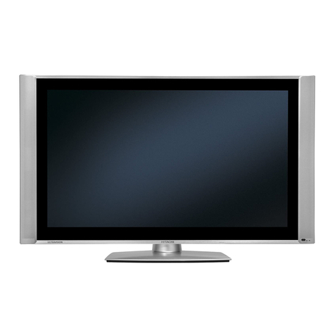
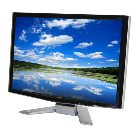
Slimax MF151S User manual

1
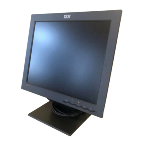
Slimax MF151S
TFT-LCD Monitor
Owner’s Manual

2
FCC INFORMATION TO THE USER
This equipment has been tested and found to comply with the limits for a Class B digital device, pursuant to
part 15 of the FCC Rules. These limits are designed to provide reasonable protection against harmful
interference in a residential installation. This equipment generates, uses and can radiate radio frequency
energy and, if not installed and used in accordance with the instructions, may cause harmful interference to
radio communications. However, there is no guarantee that interference will not occur in a particular
installation. If this equipment does cause harmful interference to radio or television reception, which can be
determinedby turningthe equipment off and on, the user is encouraged to tryto correct the interference by
one more of the following measures:
Reorient or relocate the receiving antenna.
Increase the separation betweenthe equipment andreceiver.
Connect the equipment into an outlet on a circuit different fromthatto whichthe receiverisconnected.
Consult the dealer or an experienced radio/TVtechnician forhelp.
WARNING
Changes or modifications not expressly approved by the manufacturer could void the user’s authorityto
operatethe equipment.
Information in this document is subject to change without notice.
© 2000 Max Media Inc. All rights reserved.
Not be reproduced or transferred to other documents or used for any purpose other than that for which it
was obtained without the expressed written consent ofMax Media Incorporation.
The Slimax are registered trademarks of Max Media Inc.; Microsoft, Windows ® and Windows ®NT are
registered trademarksof Microsoft Corporation; VESA, DPMS and DDC are registered trademarks of Video
ElectronicsStandard Association;All other product namesmentioned herein may be the trademarks or
registered trademarks of their respective owners.

3
Safety Instructions
!Before connecting the AC power cord to the DC adapter outlet,make sure the voltage rating of the DC
adapter correspondsto the localelectrical supply.
!Never insert anything metallicinto the cabinet openings of the liquid crystal display (LCD) monitor;
doing so may create the dangerof electric shock.
!To avoid electric shock, never touch the inside of the LCDmonitor. Only a qualifiedtechnician should
open the case of the LCDmonitor.
!Never use your LCDmonitor if the power cord has been damaged. Do not allow anything to reston the
power cord, and keep the cord awayfrom areas where people can trip overit.
!Opened ventilation of monitor cabinet isprovided forheated airto prevent overheating,these openings
should not be blocked or covered. Also, avoid using the LCD monitor on a bed, sofa, rug, or other soft
surface. Doing so may block the ventilation openingsin the side of basement. If you put the LCD monitor
in a bookcase or some other enclosed space, be sure to provide adequate ventilation.
!Don’t put your LCD monitor in a location with higher humidity and a maximum of dust.
!Do not expose the LCD monitor to rain or use it nearwater (in kitchens, near swimming pools, etc.). If
the LCD monitor accidentally gets wet, unplug it and contact an authorized dealer immediately. You can
cleanthe LCD monitor with a damp cloth whennecessary, but be sure to unplugthe LCD monitor first.
!Place the LCD monitor on a solid surface and treat it carefully. The screen is madeof thin glass with a
plastic front surface and can be damaged if dropped, hit or scratched. Do not clean the front panel with
Kenton-type materials (e.g., acetone), ethyl alcohol, toluene, ethyl acid, methyl, or chloride – these may
damage the panel.
!Put your LCD monitor near an easily accessible AC outlet.
!If your LCD monitor does not operate normally – in particular, if there are any unusual sounds or smells
coming from it – unplug it immediately and contact an authorized dealer or service center.
!High temperature can cause problems. Don’t use your LCD monitor in direct sunlight, and keepit away
from heaters, stoves, fireplaces, and other sources of heat.
!Unplug the LCD monitor when it is going to be left unused for an extended period of time.
!Unplug your LCD monitor from the AC outlet before any service.
!Inverter Fuse F1 125V 2A

4
Index
Contents of Box . . . . . . . . . . . . . . . . . . . . . . . . . . . . . . . . . . . . . . . . . . . . . . . . . . . . . . . . . . . 5
Set up . . . . . . . . . . . . . . . . . . . . . . . . . . . . . . . . . . . . . . . . . . . . . . . . . . . . . . . . . . . 6
Setting up an Ergonomic Working Environment . . . . . . . . . . . . . . . . . . . . . . . . . . . . . . . . . . . . . . 6
Monitor location . . . . . . . . . . . . . . . . . . . . . . . . . . . . . . . . . . . . . . 6
Height . . . . . . . . . . . . . . . . . . . . . . . . . . . . . . . . . . . . . . 6
Tilt . . . . . . . . . . . . . . . . . . . . . . . . . . . . . . . . . . . . . . 6
Plug and Play . . . . . . . . . . . . . . . . . . . . . . . . . . . . . . . . . . . . . . 6
Connecting Your LCD Monitor . . . . . . . . . . . . . . . . . . . . . . . . . . . . . . . . . . . . . . . 7
Installing the Monitor Driver . . . . . . . . . . . . . . . . . . . . . . . . . . . . . . . . . . . . . . . 8
Monitor Self-Test . . . . . . . . . . . . . . . . . . . . . . . . . . . . . . . . . . . . . . . 8
Help Index . . . . . . . . . . . . . . . . . . . . . . . . . . . . . . . . . . . . . . . 8
Warm-up Time . . . . . . . . . . . . . . . . . . . . . . . . . . . . . . . . . . . . . . . 8
Adjustment of Your LCD Monitor . . . . . . . . . . . . . . . . . . . . . . . . . . . . . . . . . . . . . . . 9
User Controls . . . . . . . . . . . . . . . . . . . . . . . . . . . . . . . . . . . . . . . . . . . . . . . . . . . . 9
Automatic Save . . . . . . . . . . . . . . . . . . . . . . . . . . . . . . . . . . . . . . . . . . . . . . . . . . . . 9
ON-Screen Display(OSD) . . . . . . . . . . . . . . . . . . . . . . . . . . . . . . . . . . . . . . . . . . . . . . . . . . . . 10
Accessing the menu . . . . . . . . . . . . . . . . . . . . . . . . . . . . . . . . . . . . . . . . . . . . . . . . . . . . 10
Special message . . . . . . . . . . . . . . . . . . . . . . . . . . . . . . . . . . . . . . . . . . . . . . . . . . . . 11
OSD functions and adjustment . . . . . . . . . . . . . . . . . . . . . . . . . . . . . . . . . . . . . . . . . . . . . . . . . . . . 12
Appendix . . . . . . . . . . . . . . . . . . . . . . . . . . . . . . . . . . . . . . . . . . . . . . . . . . . . 13
Pin Assignment . . . . . . . . . . . . . . . . . . . . . . . . . . . . . . . . . . . . . . . . . . . . . . . . . . . . 13
Display Modes . . . . . . . . . . . . . . . . . . . . . . . . . . . . . . . . . . . . . . . . . . . . . . . . . . . . 14
Specifications . . . . . . . . . . . . . . . . . . . . . . . . . . . . . . . . . . . . . . . . . . . . . . . . . . . . 15
Trouble Shooting . . . . . . . . . . . . . . . . . . . . . . . . . . . . . . . . . . . . . . . . . . . . . . . . . . . . 16

5
Contents of Box
Please make sure the following items are included with your monitor. If any items are missing,
contact your dealer.
User’ Manual
AC/DC Adapter
Power Cord
Monitor
15-pin D-Sub Signal Cable

6
Set up
Setting up an Ergonomic Working Environment
Consider the advice given below before you install yourmonitor.
Monitor location
Choose a positionthatexposes your monitor tothe least reflection from lightsor windows,
Usually at a right angle to anywindow.
Height
Place your LCDmonitor so that the top of the screen is slightly below your eye level when you
are comfortably seated.
Tilt
Tilt the screen until youfeel comfortableworking with yourmonitor.
Figure 1. Height and tilt the screen

7
Connecting Your LCD Monitor
Figure 2. Cable connections
A. Connect the power cord tothe DC adapter and connect the adapter jackto the DC12Vpower port
on the back of your monitor.
B. Connect the signal cable tothe video port on your computer.
Plug and Play
The adoption of the new VESA ® Plug and Play solution eliminates complicated and time consuming setup.
It allows you to install your monitor in a Plug and Play compatible system without the usual hassles and
confusion. Your PC system can easily identify and configure itself for use with your display. This monitor
automatically tellsthe PC system its Extended Display Identification Data (EDID) using Display Data
Channel (DDC) protocols so the PC system can automatically configure itselfto use the flat panel display. If
yourPC system needs a video driver, followthe instructionsgiven below according tothe operating system
your computer uses.
Installing the Monitor Driver
The 3.5” Diskette that accompanies this product contains the necessary drivers for installing your monitor.
Please refer tothe driver installation instructions included with your package for more information.

8
Monitor Self-Test
Your monitor provides a self-test function that allows you to check whether your monitor is functioning
properly. Check your monitor by followingthe steps:
Figure 3. PowerStatus Indicator
!Turn off both your computer and the monitor.
!Unplugthe video cable from the backofthe computer.
!Turn on the monitor.
!message will be shown “Power Saving Mode”
!Turn off your monitor and reconnectthe video cable;then turn on both your computer and
!The monitor. If your monitor screen remainsblank after following the previous procedure, check your
video
!Controller and computer system; your monitor is functioning properly.
Help Index
If your monitor does not display an image, check your cable connections and refer to "Troubleshooting" on
page 16. If you feel difficult to get optimized displayed image, runAuto Configuration (see page 12) and
refer to "Adjusting Your LCD Monitor " on page 9 or "Troubleshooting" on page 16.
Warm-up Time
All LCD monitors needtimeto becomethermally stable whenever you turn onthe monitor afterlettingthe
monitor be turned off for a couple of hours. Therefore,to achieve more accurate adjustments for parameters,
allow the LCDmonitor towarm (be on) for at least 30minutes before making any screen adjustments.

9
Adjustment of Your LCD Monitor
User Controls
Your LCD monitor allows you to easily adjust the characteristics of the image being displayed.
All ofthese adjustments are made using the control buttonsonthe front ofthe monitor. While
you use these buttons to adjustthe controls, an on-screen menu showsyou their numeric
values as they change.
Figure4 . User control locations
Table 1. User Control Buttons descriptions
No. Name Descriptions
menu !OSD (On Screen Display) On/OFF
!Sub Menu Exit
α<!OSD Menu Navigation right direction
!Selected Menu Value control
!Brightness Direct Access
β>!OSD Menu Navigation left direction
!Selected Menu Value control
!Brightness Direct
χenter !OSDMenuSelect
!Auto Configuration Direct Access
δPower !Turns on and off Power the monitor
εLED indicator !Green : Normal Operation
!Amber : PowerSaving Mode or Disconnected Signal Cable
!Off : Turnsoffthe monitor
Automatic Save
Whenever you open the on-screen menu and allow an adjustment window to remain active for about 40
seconds without pressing other buttons, the monitor automatically saves any adjustment you have made.
These changes are saved into a user NVRAM(Non Volatile RAM) in the monitor.
The monitor can save adjustments for up to 5 user modes. It has 13 factory preset or preload modes, one for
each signal frequency as listed in table 7 on page 14. If youhave made no adjustments, the on-screen menu
disappears and the monitor does not save anything.

10
ON-Screen Display(OSD)
Figure 5 . On-Screen Display(OSD)
Accessing the menu
!With the OSD off, push the menu button to display themain OSDmenu.
!Use the < > buttons to move from one function to another function When you move from one icon to
another, the function name changes to reflect the function or group of functions represented by that icon.
See Table 1 starting onthe next page to view a
!complete list of all of the functions available forthe monitor.
!Press the menu button onceto activate thehighlighted function,then selectthefunction and adjust the
value.
!Use enter buttons to select the sub-menu, and press the enter button once tomove at the sub-menu.
!After selecting afunction, use < > buttons to adjust value setting bar moves and the numeric value
indicator changes to response your adjustments.
NOTE : The numeric value indicator is provided as a point of reference only and has nothingto do with a
real measurement.
!Press the menu button a couple oftimesto returnto the main menuto select another function or toexit
from the OSD.

11
Special message
Figure 6 . Auto Configuration execution message
Figure 7 . PowerSaving Message
Figure 8 . Input mode not supportedmessage
These messages show special status
“Please Wait” means the monitor is executing self-adjust to optimize input video signal.
“Power Saving Mode” means the monitor is going to do power saving function
“ Input NoSupported” means the monitor can not display properlybecause input signal isout of display
range.

12
OSD functions and adjustment
Table 2. On Screen Display controls
Icons Name Descriptions
Auto Configuration !"Auto configuration” allows the monitor to self-adjustto
the incoming video signal. The values of phase, clock and
position are adjusted automatically
Brightness !"Brightness” allows for user to control backlight
brightness
!.
Contrast !"Contrast” allows for user to control gain of input video
signal level.
Phase / Clock !“Phase/Clock” allows for user to get optimized image.
!“Phase” – fine tune up image
!“Clock” – rough tune image
Color Temperature !“Color Temperature” allows for user to select color
modes
!“9300 K” Bluish White
!“6500 K” Plain White
!“User” User can control Black level and R, G and B color
Position !“Position” allows for user to control display poison
!“ Horizontal” Horizontal direction
!“Vertical” Vertical direction
OSD Position !“OSD Position” allows for user to control OSD display
poison
!“ Horizontal” Horizontal direction
!“Vertical” Vertical direction
Timeout /Sec !“Timeout /Sec” allows for user to control OSD display
time from 10 to 60 seconds
Backlight Time !“Backlight Time” allows for userto check used time. It is
timeof monitorturn on and displayed time
Reset !“Reset” allows for userto initialize adjusted valueexcept
backlight time.
When you select some menu which becomes highlighting and press enter button go into sub menu .
At the sub-menu, enter button is selecting key.

13
Appendix
Pin Assignment
Table 3. Pin Assignment of 15 Pin D-sub Connector
1Red
2Green
3Blue
4GND
5DDC GND
6Red GND
7Green GND
8Blue GND
9No Connection
10 Sync GND
11 GND
12 DDC-SDA
13 H-Sync
14 V-Sync
15 DDC-SCL
Shell GND
Pin Name

14
Display Modes
Table 3. Display preset modes
No Mode Resolution Sync Polarity Pixel Frequency Sync Frequency
H(Pixels) +31.468 KHz
1640 x 350 V(Lines) -25.175 MHz 70.0 Hz
H(Pixels) -31.468 KHz
2720 x 400 V(Lines) +28.322 MHz 70.0 Hz
H(Pixels) -31.469 KHz
3640 x 480 V(Lines) -25.175 MHz 60.0 Hz
H(Pixels) -35.00 KHz
4640 x 480 V(Lines) -30.24 MHz 66.67 Hz
H(Pixels) -37.50 KHz
5
VGA
640 x 480 V(Lines) -31.5 MHz 75.0 Hz
H(Pixels) +35.156 KHz
6800 x 600 V(Lines) +36.0 MHz 56.25 Hz
H(Pixels) +37.879 KHz
7800 x 600 V(Lines) +40.0 MHz 60.3 Hz
H(Pixels) +48.077 KHz
8800 x 600 V(Lines) +50.0 MHz 72.188 Hz
H(Pixels) +46.875 KHz
9
SVGA
800 x 600 V(Lines) +49.5 MHz 75.0 Hz
H(Pixels) -49.725 KHz
10 MAC 832 x 624 V(Lines) -57.2832 MHz 74.55 Hz
H(Pixels) -48.363 KHz
11 1024 x 768 V(Lines) -65 MHz 60.0 Hz
H(Pixels) -56.476 KHz
12 1024 x 768 V(Lines) -75 MHz 70.0 Hz
H(Pixels) +60.023 KHz
13
XGA
1024 x 768 V(Lines) +78.75 MHz 75.0 Hz

15
Specifications Table 4. Technical and other specifications
Category Items Descriptions
Image
Display Type
Diagonal Size
Pixel Pitch
Active Matrix Color TFT LCD
15.1” (H: 30.7cm, V: 23 cm, D: 38cm)
0.3 mm * 0.3 mm
Optical
Luminance
Color Temperature
6500K
9300K
Viewing Angle
Contrast Ratio
Color Depth
170 cd/m2(min.), 200 cd/m2(typ.)
6500K, 9300K, User
x = 0.320 ±0.03, y = 0.340 ±0.03
x = 0.281 ±0.03, y = 0.297 ±0.03
110 Deg.(H),80 Deg.(V)<Typ.>
150 : 1(Min.)
262,144 (6 bits)
Electrical
Input Frequency
Max. Resolution
Connector
Control type
User control
Power Input Volts/Freq
Power Consumption
Horizontal : 31~60kHz / Vertical : 56~75Hz
XGA 1024 * 768 @75Hz
15Pin D-SUB
Digital OSD Control
5 key buttons
100 ~ 240 VAC(Power Free) 50/60Hz
Max. [25W], PowerSaving Mode [5W]
Plug & Play DDC
EDID
2B
1.3
Mechanical
Dimension Set Size
Box Size
Weight Net
Gross
399 * 139 * 361.5mm [W*D*H]
517 * 139 * 361.5mm [W*D*H]
5.6Kg
7.1Kg
Environment
Operation Temperature
Humidity
Storage Temperature
Humidity
50•to 104 •(10 •to 40 •)
10% to 80%
13•to 113 •(-25 •to 45 •)
5% to 95%
Regulatory
Safety
CE Mark
EMI
VCCI
MIC
UL 1950, CSA C22.2 No. 950 /EN60950 / EMKOS
CISPR22 Class B / EN50082.1 / EN61000-3-2
FCC Class B/ IC Class B
Class B
Class B

16
Trouble Shooting
If you have a problem to set up or to use your LCD monitor, you may be able to solve it yourself. Before
contacting customer service, try the suggested actions that are appropriate to your problem.
Table 5. Trouble shooting guide
Symptoms Corrective Action Reference
Blank Screen
Power Indication is off
Make sure that the power cord is
firmly connected
Connecting your LCDmonitor,
- page 8.
Power indicator is Amber
“Power saving Mode”
Make sure that the signal cable is
firmly connectedto PC
Make sure that PC isturned on.
Connecting your LCDmonitor,
- page 8.
Power indication is Green
“Input Not Supported”
Make sure max. resolution and
frequency of Video adapter of PC and
check your video card support DDC
and Plug and Play.
Display modes
– page 15
Specification
– page 16
Too dark or high Image Control Brightness or Contrast OSD functions and adjustment
-page 13
Horizontal vertical noise
or jitter
Execute theAuto Configuration
Controlthe Phase and Clock
OSD functions and adjustment
-page 13
Horizontal or vertical
position isnotto center
Execute theAuto Configuration
Controlthe Position
OSD functions and adjustment
−παγε 13
Table of contents
