Slingsby T-37 Skylark User manual

V 1.10 11/14/2018
1
1/3-Scale Slingsby T-37 Skylark ~ by Peter Goldsmith Designs
Wings
•Wings are constructed in four panels. Panels
are joined by laminated plywood joiners with
the inner two panels permanently joined
around a center laminated rib.
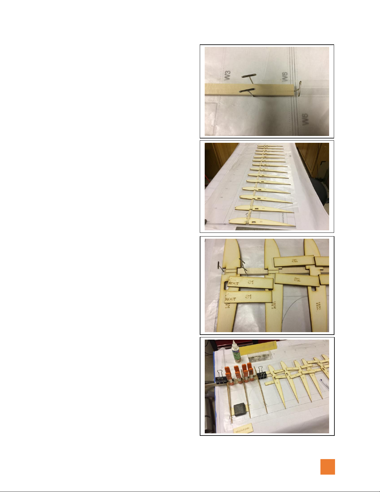
•Locate the plywood center wing joiner parts
and the center rib plywood and G10 parts.
Stick T-pins through alignment holes and
epoxy parts together.
•The center and outboard wing joiners are three
pieces of plywood laminated together. The center
rib is three pieces of plywood and two pieces of
G10 laminated together with the G10 added to
the outsides of the lamination.
•Locate all the wing ribs and shear web parts,
break them out of the laser cut sheets, lightly
sand off the nubs, and group them in order.
This helps ensure that you have all the
necessary parts identified and speeds the
build process.
•Peter recommends NOT build the wing
panels over the plans, but rather to use the
plan as a reference. The reason is the paper
plans can change dimension with time and
humidity causing a mismatch between the
parts and the plan. Establish and straight
reference line on your building surface and
scribe a perpendicular reference line at one
end. Align the lower spar with the reference
line running down the worksurface and the
first wing rib with the perpendicular
reference line.
V 1.10 11/14/2018
2
•For many kit builders, building over the plan
is preferred…so we used the plan just to see
how well things would go. First step is to get
the lower spar pinned into place.
•Locate all the ribs and shear webbing for
each wing. Study the plan and arrange the
pieces in order. Note that the shear webs
have a top and bottom as well as a left and
right. Make sure you have these properly
oriented as you glue them in place.
•Note the laser cut dotted lines between the
top and bottom spars on W1 ribs. This area
will get removed at a later step. Note also the
dihedral angle on the root side of shear web
S1. This sets the angle the root ribs of the
center sections.
•The S1 and S2 shear webs set the spacing
between the W1 and W2 ribs. They also form
the “box” that the spar joiner blade will fit
into. You can cover one of the plywood spar
joiners with wax paper and use it as a spacer
when gluing in S1 and S2 parts.
•This same “box” will be created at the
outboard end of the center panels and on the
inboard end of the tip panels. Add the stack
of wing bolt plates (note that it is easier to
laminate these parts together and sand the
top taper before gluing them between the
ribs). These form a hard point for the wing
bolts and need to fill the space between the
top and bottom balsa wing sheeting.

V 1.10 11/14/2018
3
•Continue out board adding a shear web and
then a rib, another shear web and then
another rib. Add the spoiler servo mount
plate being very careful to get the correct
orientation. Add the TE parts along the
trailing edge (they are like mini shear webs).
The servo mounts are made to exactly fit the
Spektrum A7020 or A7050 thin wing servos.
•Glue on the top trailing edge balsa sheeting
strip. We used a piece of steel as a weight to
hold the trailing edge flat on the workbench.
(Various pieces of steel are available at
Lowe’s or Home Depot and make handy tools
for model building.)
•Glue the 3/8” x 3/8” balsa leading edge in
place and sand the top edge so it follows the
contour of the ribs. Top wing sheeting will be
glued down over this edge. One method of
applying the balsa wing sheeting is to use
Deluxe Materials Speed Bond glue and a hot
iron. Glue is applied to both surfaces to be
joined and allowed to dry. Start by ironing
along the spar and work forward over the
ribs and then on to the leading edge.
•Add the 1/8” x 1/4" basswood strips to front
and back edges of spoiler pocket. Balsa wing
sheeting and cap strips can now be added.
Study the plan to see where the sheeting fits
relative to the spoiler pocket, spar line, and
wing root area. Once the glue has set, the
wing panel can be removed from the
workbench and turned over. Fit the spoiler
servo in place and string the servo extensions
through the ribs before going on to complete
the bottom sheeting and cap strips.
V 1.10 11/14/2018
4
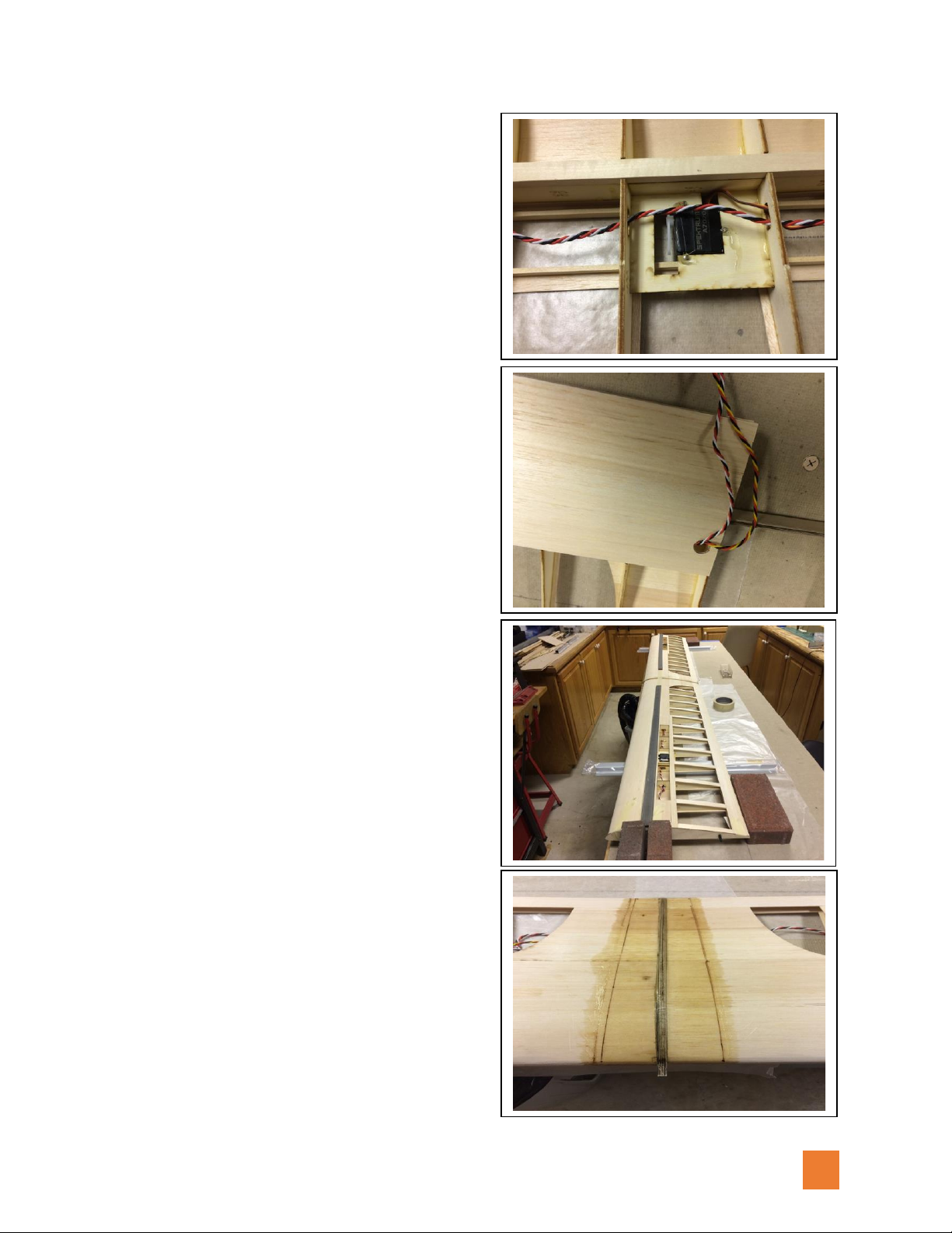
•Do not use the rubber grommets on the
servo mounts. Servos are hard mounted
directly to the servo mounting plates. Best to
program your radio, attach the servo arm,
and adjust for the correct travel of the spoiler
servo. Also make sure there is enough
clearance around the servo arm for the
spoiler door stirrup to retract down into the
wing. We applied a dot of Zap Goo to the
points of the servo mounting screws.
•Servo arm needs to be in line with the
midline of the servo case in the retracted
position and at about 70 degrees to the
midline in the fully deployed position. Make
an exit hole for the servo extension in the
bottom wing sheeting at the root end. Add
part W6b to reinforce the alignment pin hole.
•Once both center panels are completed, fit
them together over the center wing joiner
with the laminated center rib in place. The
center rib may need to be sanded to fit flush
with the top and bottom wing skins. Much
easier to do this before the panels are joined!
Prop up both wing tips an equal amount,
align the trailing edges of the two panels
along a reference line, and once satisfied
epoxy wing joiner, center rib, and two panels
together.
•Reinforce the center joint with a wrap of
fiberglass top and bottom. This hardens the
balsa surface and helps prevent crushing of
the balsa sheeting when tightening the wing
bolts.

V 1.10 11/14/2018
5
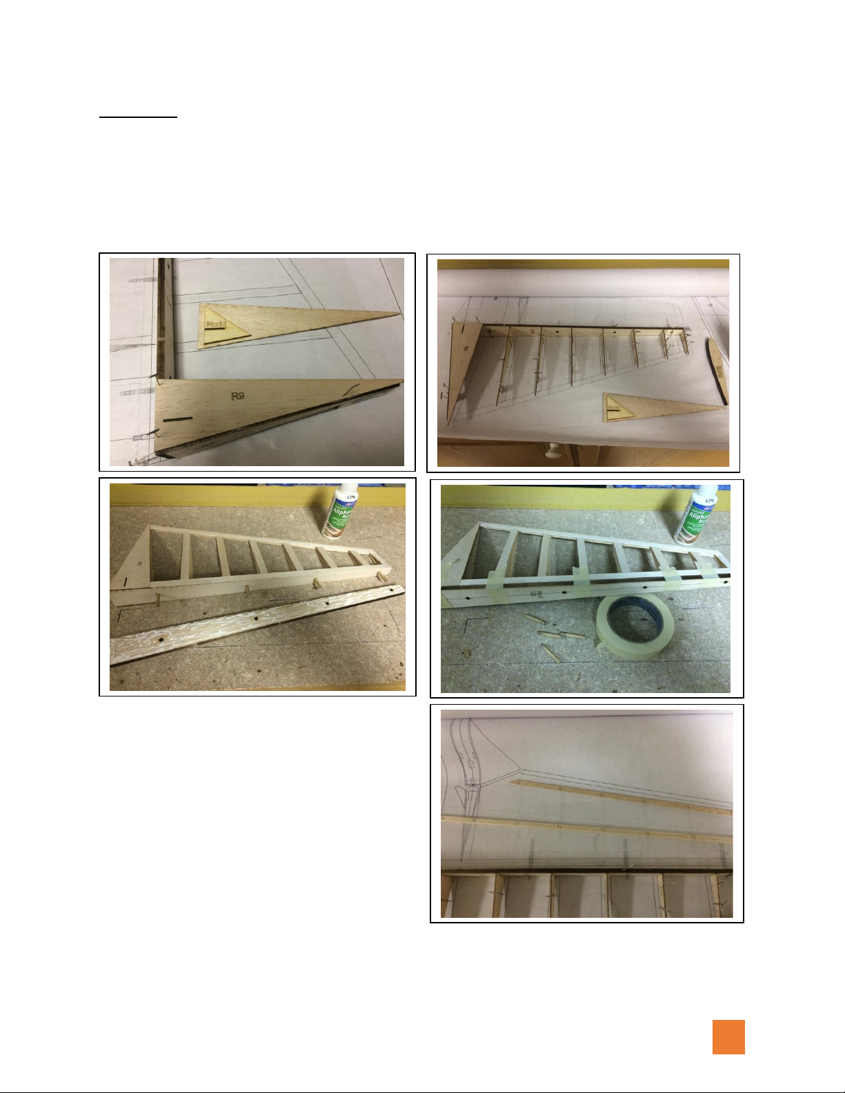
•We did not build the wing tips over the plan.
Instead, we use the reference lines on our
workbench. Take time to get the spar, first
rib, and shear webs properly aligned. The
wing tip joiner was wrapped in wax paper
and used as a spacer. Building squares were
held in place with weights while glue dried.
•Add the next rib checking that it is square
with the spar.
•Continue out the spar adding a shear web
and then a rib checking that each rib is
square with the spar. Pin the rib trailing edge
of each rib to hold it squarely in place.
•Add the aileron door support between ribs
W13 & W14
•Note that there are no shear webs after rib
W17. Keep the spacing of ribs W18 –W21
uniform with the rib spacing between W6 &
W17.
•The door to the aileron bay is also the servo
mount. Laminate the servo mount parts to
the door being careful to set the correct
orientation.
•Add the 1/8” thick balsa trailing edge to the
back of the ribs in the aileron cut out. Cut this
piece to follow the taper of the wing before
gluing in place. Once secured in place, sand
to top edge to the contour of the ribs.
V 1.10 11/14/2018
6
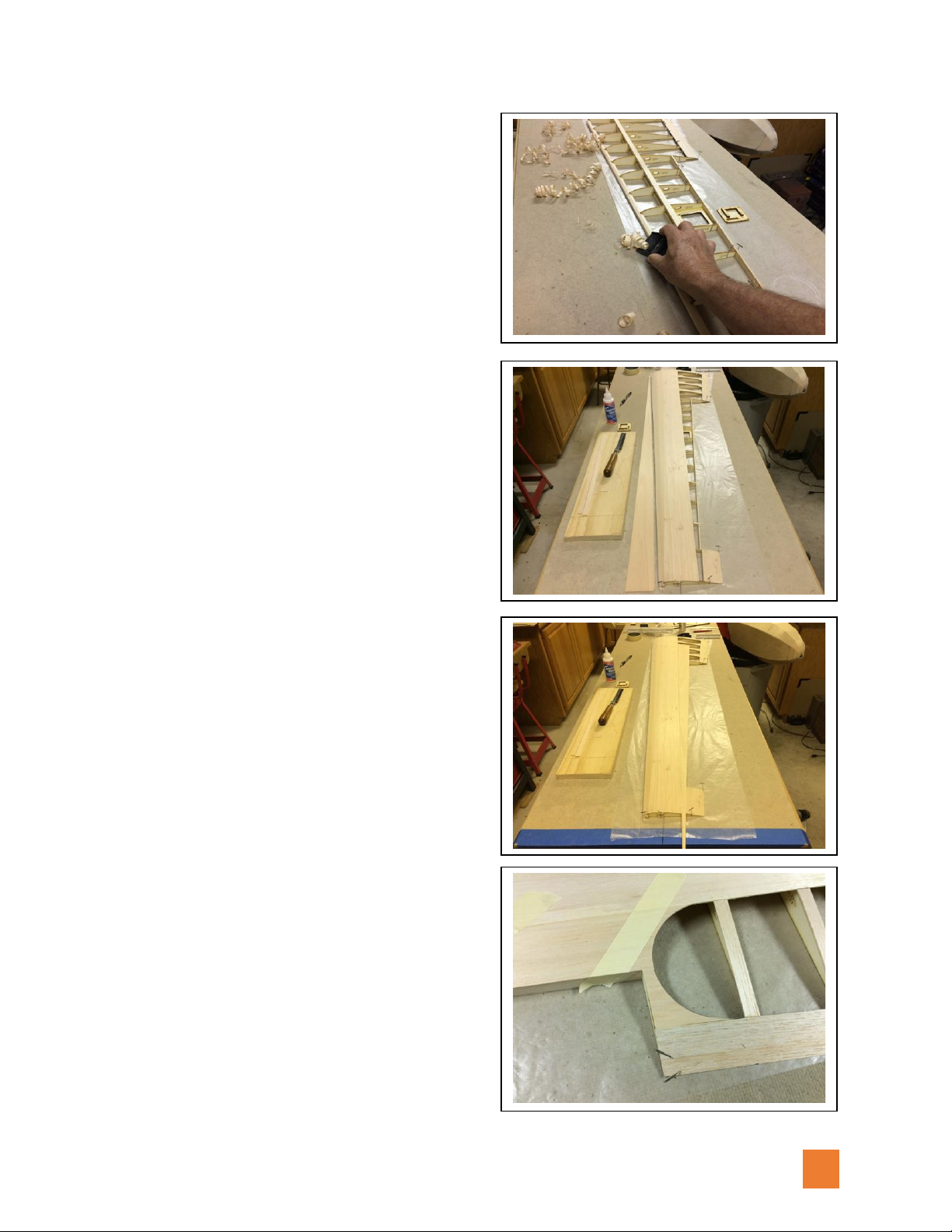
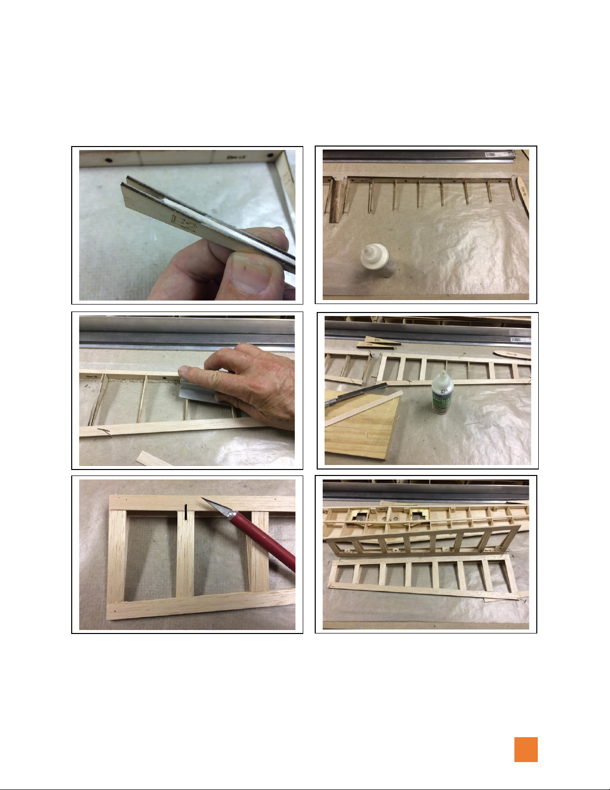
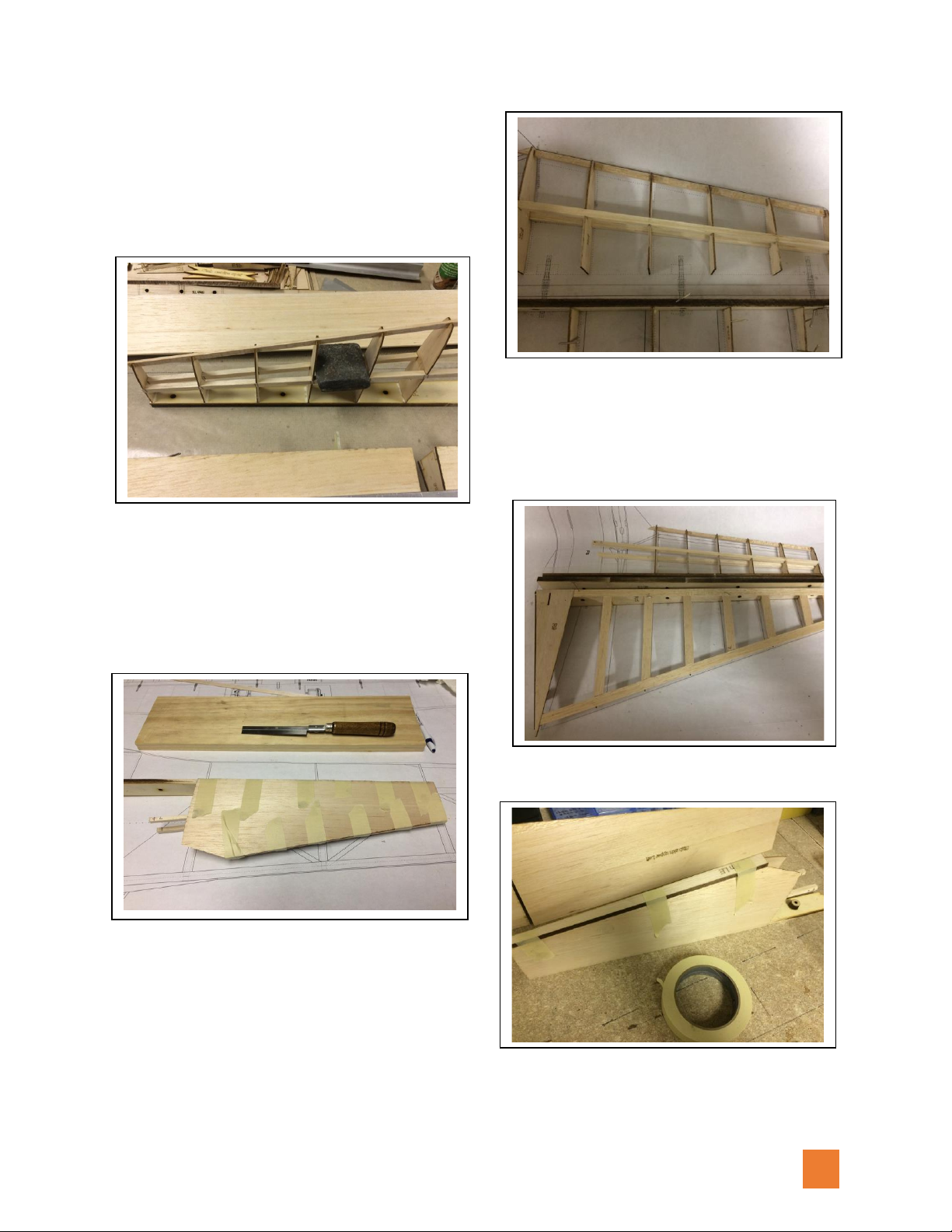
•Add top spar, top trailing edge sheeting, and
3/8” square leading edge. Shape the top of
the leading edge to follow the contour of the
ribs. Using a razor plane speeds this process.
•Lay the top wing sheeting over the wing and
mark the root and tip overhang. Cut off this
excess sheeting and save it for the next
section to be covered.
•Glue the top front section of sheeting in
place. Add top trailing edge sheeting as
shown on the plans.
•Using the excess piece cut off in the last step,
fit it in place between the top front section of
sheeting and the trailing edge of the aileron
cutout. Scribe a curve on the root end (as per
the plan) and glue in place.
•Cut a curve on another small piece to
complete the top sheeting on rib W10. Add
cap strips to ribs W6 –W9.
•Add part W6b to the inside of rib W6 to
reinforce the alignment pin hole.

V 1.10 11/14/2018
7
•Flip the wing over, install the aileron servo
extension cable and then add sheeting as was
done on the top side. The plywood end cap
rib is added, and the leading edge is sanded
round. After a final sanding to level out any
uneven joins, the wing is now ready to cover.
•Laminate all the parts together for the servo
doors/mounts. This is a good time to
program your radio and set up the servo
travel. Install the servo arm and mount the
servo on the door/mount.
•Aileron ribs are added to the bottom pre-cut
sheeting using the laser etched lines as a
guide. Add the 1/8” balsa leading edge piece
and sand it to the taper of the ribs. Add the
top sheeting and final sand the ailrons.
•The ailerons are top hinged using two strips
of covering material (one on top side and one
on the under side) to make the hinge.

V 1.10 11/14/2018
8
•First, add a strip of covering about 3/4" wide to the top edge of the aileron. Then, holding it
place against the wing in the down position, seal the strip to the wing. Then flip the aileron
over onto the top of the wing and apply a second strip of covering over the bottom side of
the hinge line. Move the aileron back to the neutral position and go over the hinge line with
your iron to seal the top and bottom pieces together. Add the G10 aileron horn in the
precut slot and make an aileron pushrod using 2-56 threaded rod and clevis.
•Bend 1/32” music wire to make the spoiler door stirrup (note sketch of this on the plans).
Stirrup needs to be about 5mm wide and extend down into the wing about 12mm (wire
should be about 17mm tall). Wire is pushed through holes in the spoiler blade, glued in
place with thin CA, and cut off flush with the outside surface.
•Place shims in the spoiler bay to raise the outside of spoiler flush with the top of the wing.
Use shims to hold the spoiler in the center of the opening to allow for friction free opening
and closing. Now you can apply a 3/4” wide strip of covering to form the hinge line. Spoiler
does not require a second strip on the underside. Servo arm pushes the spoiler open and

V 1.10 11/14/2018
9
engages the music wire stirrup to hold the spoiler closed. Springiness of the covering hinge
naturally wants to close the spoiler as will the air pressure against it in flight. There is no
direct connection between the servo arm and the spoiler blade.
Stab/Elevators
•The horizontal stabilizer and elevator halves
are tapered structures. Peter’s design
provides building tabs on the ribs that allow
these structures to be built on a flat surface.
As the ribs are removed from the carrier
sheets, be cautious to not break off these
tabs.
•Locate all the stab parts and arrange them in
order to start the build.
V 1.10 11/14/2018
10
•Pin the stab TE to a straight reference line on your workbench. Note the predrilled holes for
the hinge points. Also note the tabs that hold the hinge line level with the workbench
surface. Laminate the center S1 & S2 ribs together and glue the elevator servo mounting
plates between ribs S3 & S4. Glue all the ribs to the TE. Next, add the spar and the leading
edge. To orient yourself, the bottom of the stab facing up here.
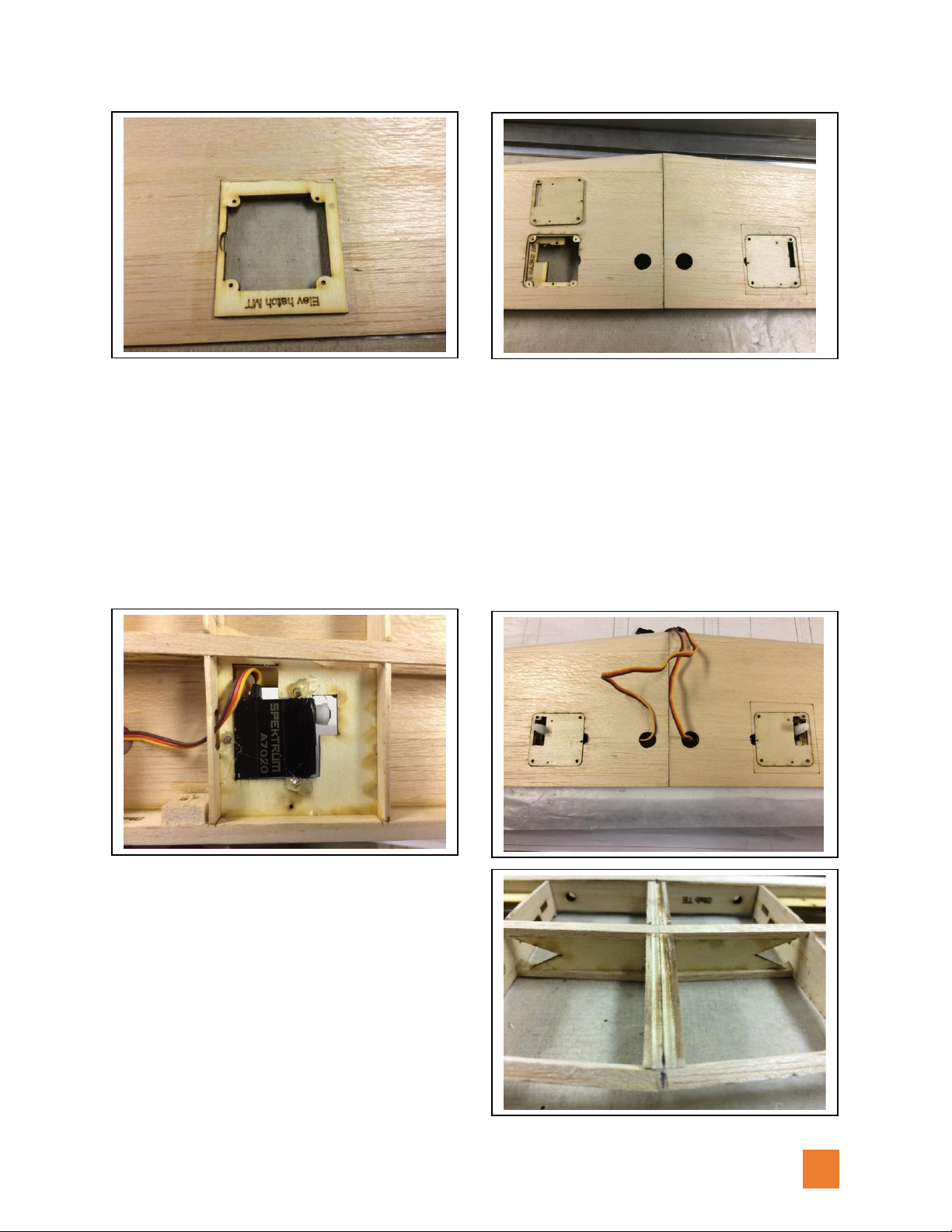
•Sand the TE to follow the contour of the ribs (be careful about pressing down too hard on
the structure so you don’t break off the leveling tabs on the ribs). Test fit the Elevator Hatch
Mount between ribs S3 and S4. It needs to fit tight against the TE and rib S3. Trim the front
side as needed to achieve this fit.
•Glue the Elevator Hatch Mount to the bottom stab skin using the laser etched outline as a
reference.
•The bottom stab skins are slightly oversize on purpose, so pay attention to this next step!
•Test fit the skin to the stab keeping the Elevator Hatch MT frame tight against rib S3 and the
TE. The center line edge where the two skins meet will need to be trimmed on each half to
make a clean center line joint.
V 1.10 11/14/2018
11
•Install the elevator servo arm and screw it to the servo mount plate. (again, this is a good
time to program your transmitter and to set the servo travel for the elevator servos). Do not
use the rubber grommets, hard mount the servo directly to the plywood plate.
•Recommended elevator servo is Spektrum A7020 thin wing servo. Use the supplied long
double arm with one side removed. Pull the servo leads through the ribs and out through
the holes in the bottom skins. No extension is needed.
•Add the balsa “donut” pieces to the inside
of the TE to extend the holes for the hinge
points. Sand the stab spar joiner to fit
between the top and bottom spars. Then,
add the top spar. Break off the build leveling
tabs and sand the TE and ribs to contour.
Add the top skins, trim off excess, and sand
leading edge round. Add Stab tips and final
sand the stab.
V 1.10 11/14/2018
12
•Elevators are constructed in a similar manner. Use a scrap piece of 1/16” balsa to make a
spacer between the E2 ribs. This forms the slot for the G10 elevator control horns. Once
constructed, add the balsa donuts to the inside of hinge point holes.
Add the LE to the elevator halves and sand it to a V along the center hinge line. Add the tips and
sand to final shape along with the stab.
V 1.10 11/14/2018
13
Fin/Rudder
•Locate all the parts to complete this section. The ribs have build tabs that allow the
structure to be assembled on a flat surface without the need for special shims. The
leading edge of the rudder is like the elevators. There are two pieces with pre-drilled
hinge point holes. One is used in the initial construction of the rudder and the second is
added later and sanded to a V along the hinge line. We used dowel pins to align parts.
•Using the plan as a reference, cut the
fin spars and leading edge to length and
mark the location of the ribs.
V 1.10 11/14/2018
14
•Dry fit the parts together and make sure
the slant of the ribs is correct according to
the plan. Once you are sure, tack together
with thin CA.
•Stand this structure on the fin tail post using the
etch lines to place the ribs and make sure the ribs
are centered over the centerline of the hinge
point holes. Once you are sure everything is
aligned, glue in place.
•Bring the fin and rudder together to check
the alignment of the hinge point holes. Add
the donuts to the inside of the fin hinge
point holes.
•Leading Pre-cut fin sheeting is added to
both sides. Excess sheeting along the
leading edge is trimmed away, leading
edge is flat sanded, and leading-edge
balsa is glued on. Finally, sand the leading
edge to a rounded shape.
V 1.10 11/14/2018
15
Fuselage
•Fuselage has a top and bottom 1/4"
square longerons that run its length.
These are constructed by scarfing
together 48” balsa and basswood sticks.
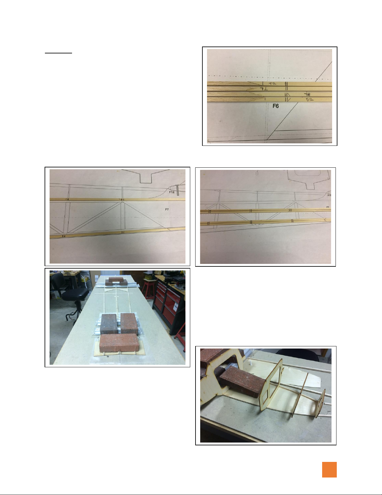
•Using the plan as a reference, transfer the
position of the formers onto a pair of the
longerons. Next, copy these marks to the
other pair of longerons. Note that the
balsa half is the front and the basswood half is the rear of the longerons. Since nearly
the entire length of fuselage is flat on the
bottom, the left and right fuselage sides were
aligned along a straight reference line on the
workbench bottom to bottom. This is an easy
way to make the left and right mirror image
fuselage sides. The longerons need to be
supported with 1/8” shims between the front
and rear plywood fuselage side panels.
We used paver bricks as weights to
keep parts flat on the bench while the
glue dries. The front balsa longerons get
bent to follow along the outside edge of
the side panels. The formers can be
used to set the spacing (but don’t glue
them in place).

V 1.10 11/14/2018
16
•Once the longerons are set, pins are used to lock the fuselage sides in place on the
workbench surface and 1/16” x 1/2" balsa strips are added to the outside of the 1/4”
square longerons. This creates a lip for the 1/4" square sticks that make the aft fuselage
formers. Add the vertical parts and then the diagonal parts to each side. Make pairs of
cross pieces (that complete the aft fuselage formers) using the plan as a reference.
•Stand the fuselage sides up over the plan. Starting at the rear, add cross pieces and
work forward pinning and clamping while keeping sides flat on the workbench.
V 1.10 11/14/2018
17
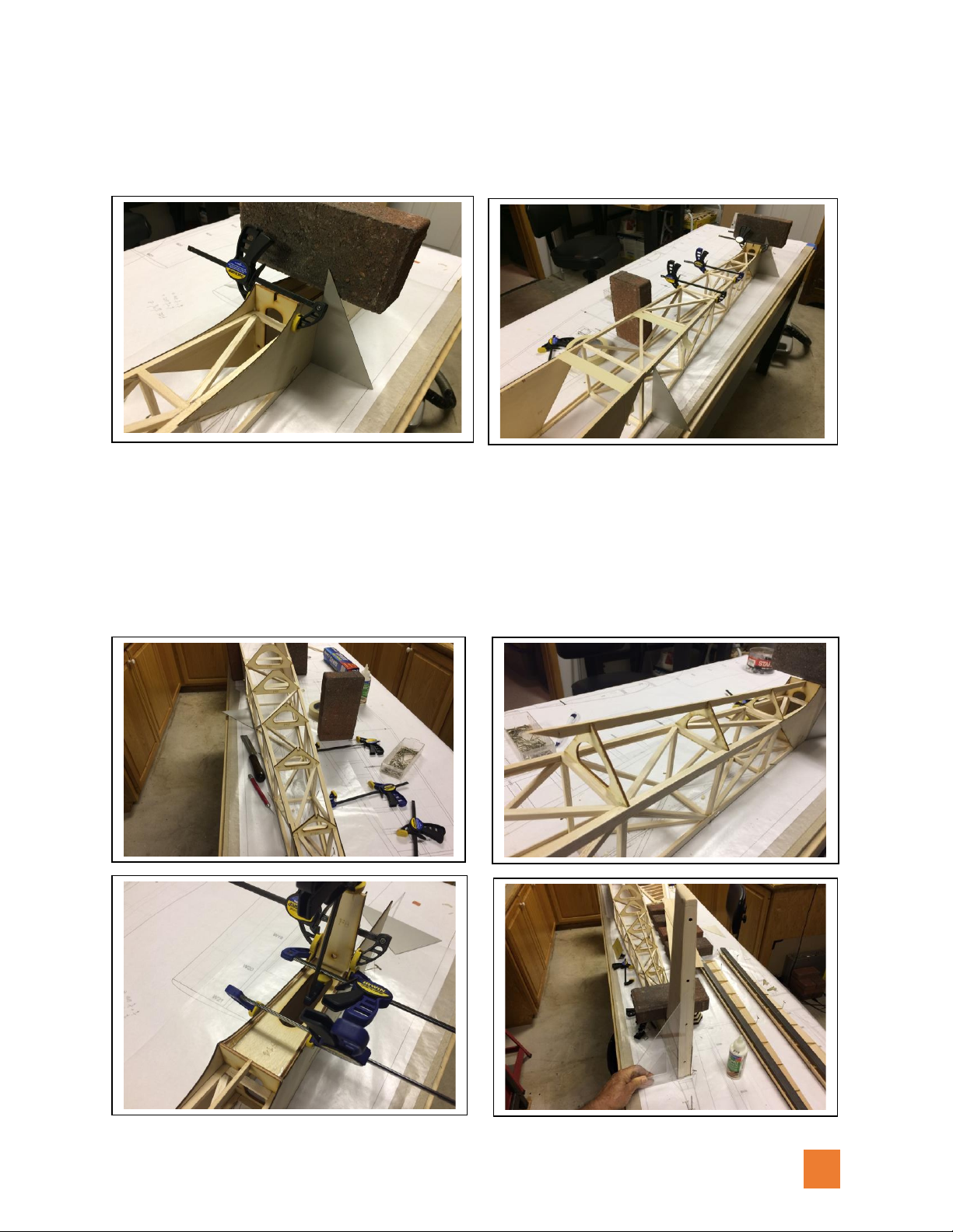
•Continue working forward adding the cross pieces and then the diagonals to form the
fuselage truss work. Use weights and builder’s triangles to keep fuselage sides
perpendicular to workbench surface.
•Add the top fuselage formers F15 –F19 and then top 1/8” x 3/8” basswood spine
between F15 and F7. Add F14 and F8. Clamp in place and check that fuselage sides
remain aligned over the plan and perpendicular to the workbench surface. Install the fin
structure into the aft fuselage section and check for fit and alignment, but don’t glue
parts together yet.
V 1.10 11/14/2018
18
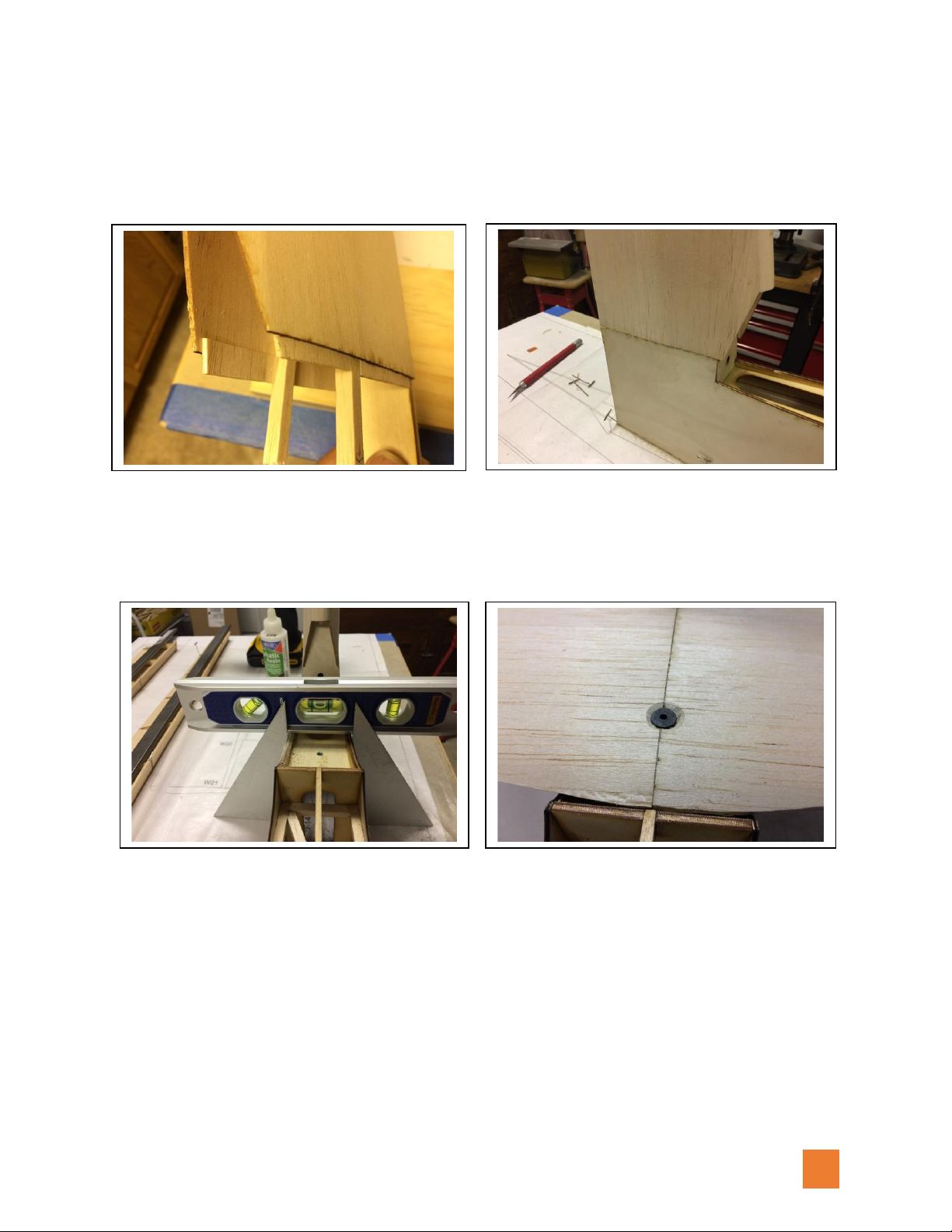
•Separate the fin from the fuselage and add pieces of 1/16” scrap balsa to the lower edge
of the fin sheeting. When the fin assembly is reinserted into the fuselage, the lip created
by adding the scrap balsa makes the joint between the plywood fuselage sides and the
fin sheeting sides blend together with a smooth joint.
•Check the stab mount for level and the fuselage sides for square. Position the stab on
the fuselage, drill hole for hold-down bolt, and install blind nut on the underside of F14.
•So far, everything has been done with the fuselage bottom flat on the workbench
surface. Because of the keel tabs on the bottom of formers F2 –F6, the fuselage will
need to be elevated to give them clearance.
•To begin, Use F1 and masking tape to pull the front fuselage sides together. Do not glue
F1 in place. Use enough masking tape that fuselage sides will not separate from F1 as
formers F2 –F6 are friction fit into place. With the fuselage elevated over a straight
reference line, sight down through the fuselage to see if the sides align. Because of the
different density and bending resistance, one side might want to be straighter than the

V 1.10 11/14/2018
19
other and cause the nose to be offset to
one side. If this happens, use a razor saw
to make partial cuts through the 1/4"
longerons on the side resistant to
bended. Make enough cuts to gain
symmetry between the sides.
•Note the lack of symmetry between the
right and left fuselage sides and the angle
of F1 to the centerline.
•Cuts were made in the right side
longerons and the sides were brought
into symmetry and F1 is now square with
the centerline.
•Block the fuselage in place over a straight
reference line and check for alignment
and level before gluing in any of the
formers F1 –F6.
•Sight down the fuselage and check for
symmetry of the sides and that fin is
perpendicular. Once satisfied, use thin CA
to tack the formers in place. Use a good
quality wood glue, like Deluxe Materials
Aliphatic Resin, to reinforce all joints
between the formers and fuselage sides.

V 1.10 11/14/2018
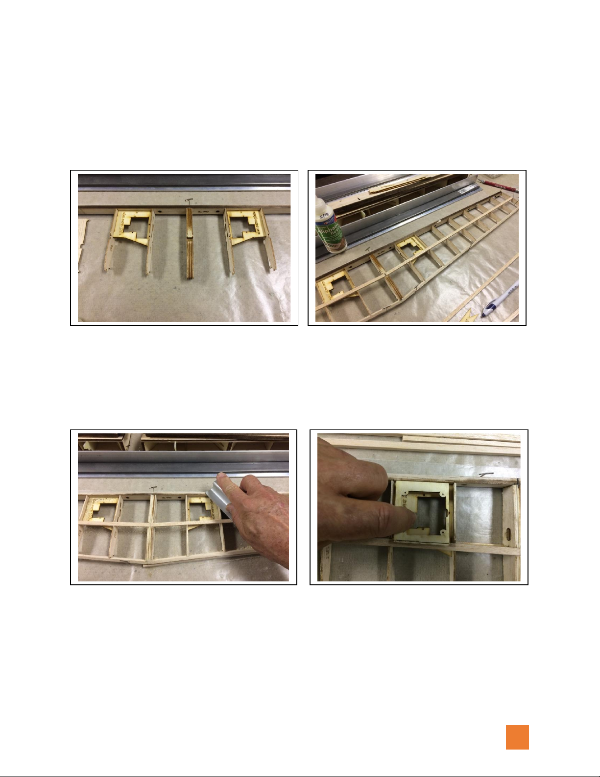
20
•Add the battery box panels, the tow hook
mount plate, and the rudder servo
mount. Make sure servos fit properly in
these mounts before gluing them in
place.
•Motor battery is an E-flite 4S 30C 14.8V
4000mAh LiPo pack.
•Tow release servo is a Spektrum A6320.
•Rudder servo is a Spektrum A5060.
•Add bent wire for the tow release and the
blind nuts for the motor mount (note that
they go on the front side of F1).
Popular Toy manuals by other brands

Lionel
Lionel SD60 owner's manual

LEGO
LEGO Super Heroes 30301 Instructions for use

Seagull Models
Seagull Models P-47D Thunderbolt 60 Assembly manual

Tamiya
Tamiya X-SA Midnisht PUMPKIN quick start guide

Value Hobby
Value Hobby Easy Stik 15 EPP ARF instruction manual

POLA G
POLA G Round iron stove + accessories manual


