manuals.online logo
Brands
  1. Home
  2. •
  3. Brands
  4. •
  5. TILLIG BAHN
  6. •
  7. Toy
  8. •
  9. TILLIG BAHN 83161 User manual

TILLIG BAHN 83161 User manual

Güterwagen
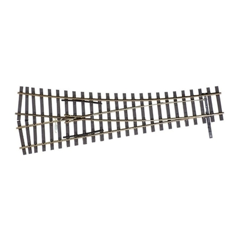
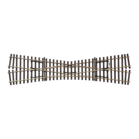
TT-Modellgleis Kreuzung 15°
TT-Advanced track system crossing • TT-Rail de modélisme croisement
TT-Modelové koleje křižovatka • TT-Modeluj ślady skrzyżowanie
www.tillig.com / www.facebook.com/tilligbahn 368361 / 19.09.2019 1
(DE) Die inneren Herzstücke der Kreuzung sind aus Plastmaterial ausgeführt. Damit stellen die beiden
Fahrwege über Gleis 1 und Gleis 2 zwei unabhängige Fahrstraßen dar. Beide Gleise können damit ohne
technische Änderung oder Schaltaufwand zwei getrennten Fahrstrombereichen angehören.
Die äußeren Herzstücke sind metallisch ausgeführt. Diese Herzstücke können wahlweise auch mit Strom
versorgt werden. Ein entsprechender Kontakt ist an beiden Herzstücken seitlich aus dem Schwellen-
band herausgeführt. Diese Stromversorgung verbessert den Fahrbetrieb zweiachsiger Triebfahrzeuge
bei langsamer Fahrt erheblich. Allerdings ist der Anschluss dieser Herzstücke entsprechend des Fahr-
weges auf Gleis 1 oder Gleis 2 zu polarisieren. Dazu bedarf es etwas technischen Aufwands, um für eine
solche Stromversorgung die Polarität entsprechend des Fahrweges zu wechseln. Dies erfolgt mittels
eines Relais (Art.-Nr. 08415). Der Einsatz eines Relais (Art.-Nr.08414) ist ebenso möglich. Bei diesem
Relais wird nur die Hälfte der Schalt-
kontakte benötigt.
Die andere Hälfte kann bei Bedarf für
das Schalten weiterer Elemente (z.B.
Signal, Bahnschranke etc.) benutzt
werden. (Abb.1)
(GB) The inner frogs of the crossing
are designed in plastic material. In
this way the two directions of travel
via Line 1 and Line 2 represent two
independent driveways. Both tracks
can thus belong to two separate trac-
tion current areas without performing
any technical changes or any e󰀨ort
involved in switching the connection.
The outer frogs are designed in metal
material. These frogs can optionally
also be powered. A corresponding
contact leads out of both frogs on the
side from the sleeper strip. This pow-
er supply considerably improves the
travelling operation of two-axle tracti-
on vehicles when they are travelling
slowly. However, the connection of
these frogs must be polarised in ac-
cordance with the direction of travel on
Line 1 or Line 2. This requires some
technical work in order to change
the polarity for such a power supply in
accordance with the direction of tra-
vel. This is performed by means of a
relay (Art. No. 08415). The use of a
relay (Art. No. 08414) is also possible.
In the case of this relay only half the
switch contacts will be required. The
other half can if necessary be used for
the switching of further elements (e.g.
signal, railway crossing etc.). (Fig.1)
368361-S.1
12.03.2014
TT-Modellgleis Kreuzung 15°
Kreuzung 15° 166 mm
Art.-Nr.: 83161
Kreuzungsgeometrie
Einbaulänge: 166 mm
Kreuzungswinkel: 15°
Abb. 1
(DE) Bitte vergleichen Sie vor dem
Montagebeginn die vorhandenen
Teile mit der Bauanleitung. Rekla-
mationen montierter oder teilmon-
tierter Bausätze können nicht aner-
kannt werden!
(GB) Before starting to assemb-
le, please check that all parts are
there by comparing them with the
building instructions. Complaints
about assembled or partially as-
sembled kits cannot be accepted!
(FR) Avant de commencer le mon-
tage, comparer les pièces dispo-
nibles avec celles gurant dans les
instructions de service. Nous ne
pouvons pas accepter les réclama-
tions concernant des kits montés
ou partiellement montés.
(CZ) Porovnejte prosím před
montáží dané součástky s návo-
dem. Reklamace smontovaných či
částečně smontovaných dílů ne-
bude brána v potaz!
(PL) Przed rozpoczęciem montażu
należy porównać otrzymane części
z instrukcją montażu. Reklamacje
złożonych lub częściowo złożo-
nych zestawów nie będą uznawane!

Art.-Nr. / Item no. / Réf. / Art.-č. / Nr art.: 83161
(DE) Kreuzung 15°, 166 mm / (GB) Railway Crossing 15°, 166 mm / (FR) Croisement 15°, 166 mm / (CZ) Křižovatka 15°, 166 mm
(PL) Skrzyżowanie 15°, 166 mm
Kreuzungsgeometrie
Einbaulänge: 166 mm
Kreuzungswinkel: 15°
Crossing geometry
Length when tted: 166 mm
Crossing angle: 15°
Géométrie d’croisement
Longueur de montage: 166 mm
Angle de croisement: 15°
Geometrie kří ž e n í
Délka: 166 mm
Úhel křížení: 15°
Geometria skrzyżowania
Długość mont.: 166 mm
Kąt skrzyżowania: 15°
368361-S.1
12.03.2014
TT-Modellgleis Kreuzung 15°
Kreuzung 15° 166 mm
Art.-Nr.: 83161
Kreuzungsgeometrie
Einbaulänge: 166 mm
Kreuzungswinkel: 15°
Abb. 1

(DE) optional 08414
(GB) optional 08414
(FR) en option 08414
(CZ) volitelný 08414
(PL) fakultatywny 08414
a
b(DE) Zubehörspannung 16V~
(GB) Accessory voltage 16V~
(FR) Tension accessoire 16V~
(CZ) Napětí příslušenství 16V~
(PL) Napięcie akcesoriów 16V~
b
c(DE) Gleis A
(GB) Track A
(FR) Piste A
(CZ) Stopa A
(PL) Tor A
c d
d(DE) Gleis B
(GB) Track B
(FR) Piste B
(CZ) Stopa B
(PL) Tor B
c
d
Güterwagen
TT-Modellgleis Kreuzung 15°
TT-Advanced track system crossing • TT-Rail de modélisme croisement
TT-Modelové koleje křižovatka • TT-Modeluj ślady skrzyżowanie
www.tillig.com / www.facebook.com/tilligbahn 368361 / 19.09.2019 2
(FR) Les cœurs intérieurs du croisement sont en matière plastique. Les
deux voies au-dessus de la voie 1 et de la voie 2 représentent donc
deux itinéraires indépendants. Les deux voies peuvent ainsi appartenir
à deux zones de courant de traction séparées sans aucune modicati-
on technique ni commutation. Les cœurs extérieurs sont en métal. Ces
cœurs peuvent, au choix, être alimenté en électricité. Un contact corre-
spondant est guidé en dehors du ruban de traverse sur les deux côtés
du cœur. Cette alimentation électrique améliore considérablement le
fonctionnement des locomotives à deux essieux en cas de marche len-
te. En revanche, le raccord de ces cœurs doit être polarisé en fonction
de la trajectoire sur la voie 1 ou la voie 2. Un certain e󰀨ort technique
est nécessaire pour modier la polarité de la trajectoire pour une telle
alimentation électrique. Cette modication est réalisée à l’aide d’un
relais (réf. 08415). L’application d’un relais (réf. 08414) est également
possible. Avec ce relais, seule la moitié des contacts de commutation
est nécessaire. L’autre moitié peut être utilisée en cas de besoin pour
la commutation d’autres éléments (par ex. le signal, les barrières de
passage à niveau, etc.). (Fig. 1)
(CZ) Vnitřní srdcovky křížení jsou vyrobeny z plastu. Oba průjezdy po
koleji 1 a koleji 2 tak představují dvě nezávislé trasy. Obě koleje tedy
mohou bez technických úprav nebo náročného zapojování patřit ke
dvěma samostatným trakčním obvodům. Vnější srdcovky jsou pro-
vedeny v kovu. Tyto srdcovky lze volitelně také napájet. Příslušný
kontakt je na obou srdcovkách vyveden bočně z pásu pražců. Toto
napájení výrazně zlepšuje jízdní provoz dvounápravových hnacích
vozidel v nízkých rychlostech. Připojení těchto srdcovek však musí
být příslušně polarizováno podle koleje 1 nebo koleje 2. Změna po-
larity pro takové napájení podle příslušné trasy tak vyžaduje určitou
technickou náročnost. Změnu zajišťuje relé (obj.č. 08415). Je také
možné použít relé (obj.č. 08414). U tohoto relé je nutná pouze polovi-
na kontaktů. Druhou polovinu lze v případě potřeby použít ke spínání
dalších prvků (např. návěstidla, železničních závor atd.). (obr.1)
(PL) Wewnętrzne krzyżownice skrzyżowania wykonane są z twor-
zywa sztucznego. W ten sposób obie drogi przejazdu przez tor 1 i
przez tor 2 są od siebie niezależne. Oba tory mogą w ten sposób,
bez zmian technicznych lub przełączania należeć do dwóch oddziel-
nych układów prądu jezdnego. Zewnętrzne krzyżownice są wykona-
ne z metalu. Mogą one, do wyboru, być również zasilane prądem.
Odpowiedni styk wyprowadzony jest w obu krzyżownicach po boku,
z wstęgi podkładów. Takie zasilanie prądem znacznie polepsza eks-
ploatację dwuosiowych pojazdów trakcyjnych przy powolnej jeździe.
Należy jednakże polaryzować przyłączenie tych krzyżownic odpow-
iednio do drogi przejazdu na torze 1 lub na torze 2. W celu zmiany
biegunowości dla takiego zasilania prądem odpowiednio do drogi pr-
zejazdu potrzeba nieco zachodu. Robi się to za pomocą przekaźni-
ka (nr art. 08415). Możliwe jest również zastosowanie przekaźnika
(nr art. 08414). W przypadku tego przekaźnika potrzebna jest tylko
połowa styków przełączeniowych. Druga połowa może być użyta w
razie potrzeby do przełączania innych elementów (np. sygnał, rogatka
itp.). (Rys.1)
(DE) Für die Ansteuerung des Relais gibt es verschiedene Möglichkei-
ten. Die einfachste Art ist ein von Hand zu betätigender Schalter (Tas-
tenpult 08211). (Abb.2) Dieser kann u. U. auch mit dem Schalten einer
Weiche für den Fahrbetrieb gekoppelt sein. Es kann auch ein Relai-
sausgang von einer elektronischen Fahrwegschaltung für das Initiali-
sieren des Polaritätswechsels benutzt werden. Weiterhin besteht die
Möglichkeit der Steuerung durch den fahrenden Zug selbst.
Die automatische Steuerung durch den Zug kann im konventionel-
lem Gleichstrombetrieb mit Gleiskontakten erfolgen. Diese Gleiskon-
takte (bei ausreichend Platz auch ein Schaltgleis 83159) sind auf der
jeweils linken Schiene vor der Kreuzung anzuordnen. Links deshalb,
weil das Relais auf eine negative Spannung reagiert und bei konven-
tionellem Betrieb “-” in Fahrtrichtung an der linken Schiene anliegt.
Damit die Fahrtrichtung auf Gleis A und B beliebig sein kann, muss
jeweils an beiden Seiten der Kreuzung in beiden Gleisen in Fahrtrich-
tung links (also auf jeder Seite in der gegenüberliegenden Schiene
am anderen Ende der Kreuzung) solch ein Kontakt angebracht wer-
den. In der Summe sind es vier solcher Schienenkontakte. Die beiden
Kontakte eines Gleises werden zusammengeschlossen an den be-
tre󰀨enden Schalteingang des Relais gelegt. Bei einem digitalen Fahr-
betrieb kann das Relais durch die Auswertung eines Ausganges der
Belegtmelder der beiden Gleise genutzt werden. Der Einbau von gleis-
unabhängigen Kontakten (z. B. Glasrohrkontakte und Magneten an den
Fahrzeugen) ist auch möglich.
(GB) There are various options for the actuation of the relay. The sim-
plest way is a switch that is to be operated manually (Control desk
08211) (Figure 2), This can also under certain circumstances be cou-
pled with the switching of a joint for the driving mode. A relay out of an
electronic route switching can also be used for the initialisation of the
polarity change. There is additionally the option of control by the moving
train itself.
The automatic control by the train can be performed in the conventional
DC operation with track contacts. These track contacts (if there is su󰀩-
cient space also a switching track 83159) shall be arranged on the left
respective rail before the crossing. On the left hand side because the
relay responds to a negative voltage and in the case of conventional
operation “-“ has contact with the left rail in the direction of travel. Such
a contact must be attached respectively to both sides of the crossing
on both lines on the left hand side in the direction of travel (i.e. on each
side in the opposite rail at the other end of the crossing) to ensure that
the direction of travel on Track A and B can be arbitrary.
368361-S.2
12.03.2014
Abb. 2
Abb. 3
TT-Modellgleis Kreuzung 15°
Abb. 4

(DE) optional
Tastenpult 08211
(GB) optional 08211
Control desk
(FR) en option Pupitre
de commande 08211
(CZ) volitelný Klávesnice 08211
(PL) fakultatywny Pulpit klawiszowy 08211
a
a
Güterwagen
TT-Modellgleis Kreuzung 15°
TT-Advanced track system crossing • TT-Rail de modélisme croisement
TT-Modelové koleje křižovatka • TT-Modeluj ślady skrzyżowanie
www.tillig.com / www.facebook.com/tilligbahn 368361 / 19.09.2019 3
(DE) Für die Kreuzung gibt es auch eine Styrostone Bettung (Art.-Nr.
86324 und 86374). Die hier vorliegende Kreuzung hat eine im Endteil
veränderte Geometrie der Schwellen gegenüber der Vorgängerversion.
Daher ist die Bettung (Art.-Nr. 86324 und 86374) dieser neuen Geome-
trie angepasst. Die bislang produzierten Bettungen (Art.-Nr. 86321 und
86371) passen daher nicht mehr ohne Veränderung, können aber den-
noch verwendet werden. Dazu sind die in der Abbildung 3 dargestellten
schmalen Streifen nach der letzten durch beide Gleise durchgehenden
Schwelle herauszuschneiden.
Soll die für die neue Kreuzung vorgesehene Gleisbettung (Art.-Nr.
86324 und 86374) für eine alte Kreuzung verwendet werden, so ist die-
se Bettung ebenfalls nach der letzten durchgehenden Schwelle durch-
zuschneiden (Abb.4). Die entstehende Lücke ist nach der Montage
auf der Grundplatte individuell mit entsprechendem Schotter (Art.-Nr.
86406 oder 86407) aufzufüllen.
(GB) There is also a Styrostone track bedding for the crossing (art. no.
86324 and 86374). The crossing present here has a geometry of the
sleepers that has been transformed in the nal section compared to the
previous version. That is why the track bedding for the crossing (art.
no. 86324 and 86374) has been adapted to this new geometry. The
track beddings produced to date (art. no. 86321 and 86371) therefore
no longer t without being changed, but can nevertheless still be used.
To this end the narrow strips depicted in Figure 3 shall be cut out after
the last sleeper that crosses both lines. If the track bedding intended
for the new crossing (art. no. 86324 and 86374) should be used for an
368361-S.2
12.03.2014
Abb. 2
Abb. 3
TT-Modellgleis Kreuzung 15°
Abb. 4
368361-S.2
12.03.2014
Abb. 2
Abb. 3
TT-Modellgleis Kreuzung 15°
Abb. 4
Art.-Nr. / Item no.
Réf. / Art.-č.
Nr art.: 86321
86371

Art.-Nr. / Item no.
Réf. / Art.-č.
Nr art.: 86324
86374
In total there are four such rail contacts. The two contacts of a line are
placed connected together at the respective switch input of the relay. In
the case of a digital drive mode, the relay can be used by means of the
evaluation of an output of the track occupancy sensors of the two lines.
The installation of contacts that are independent of the line (e.g. glass
tube contacts and magnets on the vehicles) is also possible.
(FR) Il existe di󰀨érentes possibilités pour la commande du relais. La
manière simple est d’activer le commutateur manuellement (pupitre de
commande 08211). (Fig. 2) Dans certains cas, celui-ci peut également
être couplé à la commutation d‘un aiguillage pour la conduite. Une sor-
tie relais d‘un circuit électronique de trajectoire peut également être uti-
lisée pour initialiser le changement de polarité. La commande par le
train lui-même est possible.
La commande automatique par le train peut être réalisée dans le mode
conventionnel à courant continu avec les contacts de voie. Ces cont-
acts de voie (ou une voie de télécommande 83159 si l’espace est suf-
sant) doivent être disposés sur le rail gauche en face du croisement.
À gauche parce que le relais réagit à une tension négative et qu‘en
fonctionnement conventionnel « - » est appliqué au rail gauche dans le
sens de la marche. Pour pouvoir choisir le sens de marche sur les voies
A et B, un tel contact doit être installé des deux côtés du croisement
sur les deux voies dans le sens de marche à gauche (c‘est-à-dire de
chaque côté du rail opposé à l‘autre extrémité du croisement). Au total,
il y a quatre contacts de rail de ce type. Les deux contacts d’une voie
sont installés raccordés sur l’entrée de commutation correspondante
du relais. En mode numérique, le relais peut être utilisé en évaluant
une sortie des détecteurs de présence des deux voies. Le montage de
contacts indépendants de la voie (par ex. des contacts en tube de verre
et des aimants sur les véhicules) est également possible.
(CZ) Pro ovládání relé existují různé možnosti. Nejjednodušším
způsobem je ručně ovládaný spínač (klávesnice 08211). (obr.2) Ten
může být případně také spojen se spínáním výhybky pro jízdu. K
inicializaci změny polarity je také možné použít reléový výstup z elekt-
ronického kolejového spínače. Kromě toho existuje možnost ovládání
samotným jedoucím vlakem.
Automatické ovládání vlakem může být v běžném stejnosměrném pro-
vozu zajištěno kolejovými kontakty. Tyto kolejové kontakty (v případě
dostatku místa také spínací kolejnice 83159) musí být umístěny vždy
na levé kolejnici před křížením. Vlevo proto, protože relé reaguje na
záporné napětí a v běžném provozu je „-“ na levé kolejnici ve směru
jízdy. Aby mohl být směr jízdy na koleji A a B libovolný, musí být na
obou stranách křížení v obou kolejích ve směru jízdy vlevo (tj. na
každé straně v opačné kolejnici na druhém konci křížení) umístěn ta-
kový kontakt. Ve výsledku se tedy jedná o čtyři takové kolejové kon-
takty. Oba kontakty jedné koleje jsou společně přivedeny na příslušný
spínací vstup relé. V případě digitálního provozu lze relé použít tak, že
se vyhodnotí výstup detektorů obsazenosti obou kolejí. Je také možná
instalace kontaktů nezávislých na koleji (např. kontakty ze skleněných
trubic a magnety na vozidlech).
(PL) Istnieją różne możliwości sterowania przekaźnikiem. Najprost-
szym sposobem jest przełącznik uruchamiany ręcznie (pulpit klawis-
zowy 08211). (Rys. 2) Może on m. in. być sprzężony z przełączaniem
zwrotnicy w trybie jezdnym. Do inicjacji zmiany biegunowości można
użyć również wyjścia przekaźnika elektronicznego przełączania drogi
przejazdu. Ponadto istnieje możliwość sterowania przez sam jadący
pociąg. Automatyczne sterowanie przez pociąg może następować w
konwencjonalnym trybie prądu stałego ze stykami torowymi. Takie
styki torowe (w przypadku wystarczającego miejsca również tor pr-
zełączający 83159) należy rozmieścić na lewej szynie przed skrzyżo-
waniem. Po lewej stronie dlatego, że przekaźnik reaguje na ujemne
napięcie, a w konwencjonalnym trybie pracy “-” w kierunku jazdy przy-
łożony jest do lewej szyny. Aby kierunek jazdy na torze A i B mógł być
dowolny, po każdej stronie skrzyżowania, na obu torach w kierunku
jazdy po lewej stronie (czyli po każdej stronie na przeciwległej szynie
na drugim końcu skrzyżowania) należy umieścić taki styk. W sumie są
to cztery takie styki szynowe. Oba styki jednego toru kładzie się razem
na danym wejściu łączeniowym przekaźnika. W przypadku cyfrowego
trybu jezdnego można korzystać z przekaźnika poprzez analizę wyjś-
cia sygnalizatora obciążenia obu torów. Możliwy jest również montaż
niezależnych od toru styków (np. styki w rurkach szklanych i magnesy
w pojazdach).
Güterwagen
TT-Modellgleis Kreuzung 15°
TT-Advanced track system crossing • TT-Rail de modélisme croisement
TT-Modelové koleje křižovatka • TT-Modeluj ślady skrzyżowanie
www.tillig.com / www.facebook.com/tilligbahn 368361 / 19.09.2019 4
(DE) Technische Änderungen vorbehalten! Bei Reklamationen wenden Sie sich bitte an Ihren Fachhändler.
(GB) Subject to technical changes! Please contact your dealer if you have any complaints.
(FR) Sous réserve de modications techniques! Pour toute réclamation, adressez-vous à votre revendeur.
(CZ) Technické změny vyhrazeny! Při reklamaci se obraťte na svého obchodníka.
(PL) Zastrzega się możliwość zmian technicznych! W przypadku reklamacji prosimy zgłaszać się do specjalistycznego sprzedawcy.
TILLIG Modellbahnen GmbH
Promenade 1, 01855 Sebnitz
Tel.: +49 (0)35971 / 903-45 •Fax: +49 (0)35971 / 903-19
(DE) Hotline Kundendienst • (GB) Hotline customer service • (FR) Services à la clientèle Hotline • (CZ) Hotline Zákaznické služby
(PL) Biuro Obsługi Klienta: www.tillig.com/Service_Hotline.html
(DE) Bitte beachten Sie: Für dieses TILLIG-Produkt gilt der gesetzliche Gewährleistungsanspruch von 24 Monaten ab Kaufdatum. Dieser Gewährleistungsanspruch
erlischt, wenn kundenseitige Eingri󰀨e, Veränderungen, Umbauten usw. an dem Produkt erfolgen/vorgenommen werden. Bei Fahrzeugen mit eingebauter Schnittstelle,
können Gewährleistungsansprüche nur geltend gemacht werden, wenn das betre󰀨ende Fahrzeug im Lieferzustand (ohne eingebautem Digitaldecoder, mit eingestecktem
Entstörsatz) an den Fachhändler zurück gegeben wird.
(GB) Please note: This TILLIG product is subject to the statutory warranty entitlement of 24 months from the date of purchase. This warranty claim expires if the product is
interfered with, modied or converted after the point of time of the customer acquiring ownership. Where vehicles have an integrated interface, claims for warranty can only
be asserted if the vehicle concerned is returned in an as-delivered state (without built-in digital decoder, with plugged-in interference suppression kit).
(FR) Attention: Pour ce produit TILLIG, le droit de garantie légal de 24 mois à partir de la date d’achat s’applique. Ce droit de garantie s’éteint si le client procède/a procédé
à des interventions, des modications, des transformations, etc. sur le produit. Pour les véhicules à interface intégrée, les droits de garantie ne peuvent être acceptés que
si le véhicule correspondant est restitué au revendeur dans l’état de livraison (sans décodeur numérique intégré, avec l’antiparasite installé).
(CZ) Upozornění: Pro tento výrobek TILLIG platí zákonný záruční nárok 21 měsíců od data koupě. Tento záruční nárok zaniká, pokud byly ze strany zákazníka na výrobku
provedeny zásahy, změny, přestavby atd. U vozidel se zabudovaným rozhraním mohou být záruky uplatněny jen tehdy, když bude předmětné vozidlo vráceno do odborné
prodejny v původním stavu (bez zabudovaného digitálního dekodéru, se zasunutou odrušovací sadou).
(PL) Należy mieć na względzie, że: dla niniejszego produktu TILLIG obowiązuje ustawowe roszczenie gwarancyjne, wynoszące 24 miesiące od daty zakupu.
Roszczenie gwarancyjne wygasa w sytuacji, gdy przeprowadzone zostaną w produkcie zmiany lub klient dokona przebudowy produktu na własną rękę. W pojazdach z
zabudowanym interfejsem, roszczenia gwarancyjne mogą być podnoszone jedynie, gdy dany pojazd przekazany zostanie przedstawicielowi handlowemu w stanie, jaki
obowiązywał w momencie dostawy (bez zabudowanego dekodera cyfrowego, z osadzonym zestawem odkłócającym).
(DE) Nicht geeignet für Kinder unter 14 Jahren wegen abnehmbarer und verschluckbarer Kleinteile und Verletzungsgefahr durch funktionsbedingte
scharfe Ecken und Kanten. Dieses Produkt darf am Ende seiner Nutzungsdauer nicht über den normalen Hausmüll entsorgt werden, sondern muss an einem
Sammelpunkt für das Recycling von elektrischen und elektronischen Geräten abgegeben werden. Bitte fragen Sie bei Ihrem Händler oder der Gemeindeverwal-
tung nach der zuständigen Entsorgungsstelle.
(GB) Not suitable for young people under the age of 14 due to the small parts that can be removed and swallowed and risk of injury due to functi-
on-related sharp corners and edges. When this product comes to the end of its useful life, you may not dispose of it in the ordinary domestic waste but must
take it to your local collection point for recycling electrical and electronic equipment. If you don’t know the location of your nearest disposal centre please ask your retailer or the local council o󰀩ce.
(FR) Ne convient pas aux enfants de moins de 14 ans en raison de pièces pouvant être retirées et avalées et du risque de blessure en raison de coins et de bords vifs dus au fonc-
tionnement. À la n de sa durée de vie, ne pas éliminer ce produit avec les déchets ménagers mais le remettre à un point de collecte pour le recyclage d’appareils électriques et électroniques.
Veuillez vous adresser à votre revendeur ou à l’administration communale pour connaître les points d’élimination compétents.
(CZ) Není určené pro děti mladší 14ti let. Obsahuje funkční a odnímatelné malé a ostré součásti a hrany. Tento produkt nesmí být na konci svého užívání zlikvidován jako běžný domovní odpad,
ale musí být zlikvidován např. ve sběrném dvoře. Prosím, zeptejte se vašeho obchodníka, popř. na svém obecním úřadě o vhodném způsobu likvidace.
(PL) Nieodpowiednie dla dzieci poniżej 14 roku życia z uwagi na niebezpieczeństwo połknięcia i zadławienia się drobnymi częściami oraz możliwość skaleczenia się ostrymi końcówkami
i krawędziami części funkcyjnych. Produkty oznaczone przekreślonym pojemnikiem po zakończeniu użytkowania nie mogą być usuwane razem z normalnymi odpadami domowymi, lecz muszą
być przekazywane do punktu zbierania i recyklingu urządzeń elektrycznych i elektronicznych. Dzięki recyklingowi pomagają Państwo skutecznie chronić środowisko naturalne. Prosimy zwrócić się
do specjalistycznego sklepu lub do odpowiedniego urzędu w Państwa okolicy, aby dowiedzieć się, gdzie jest najbliższy punkt recyklingu urządzeń elektrycznych i elektronicznych.
0-3
0-3
old crossing, then this bedding shall also be cut through following the
last sleeper that crosses both lines (gure 4). The resulting gap shall
be lled in following assembly on the base plate using the appropriate
ballast (art. no. 86406 or 86407).
(FR) Un ballast Styrostone est également disponible pour le croisement
(réf. 86324 et 86374). Le présent croisement a une géométrie modiée
des traverses dans la partie nale par rapport à la version précéden-
te. Par conséquent, le ballast (réf. 86324 et 86374) est ajusté à cette
nouvelle géométrie. Les ballasts produits jusqu’à présent (réf. 86321
et 86371) ne sont plus adaptés sans modication mais peuvent encore
être utilisés. Pour cela, découpez les bandes étroites illustrées sur la
gure 3 après la dernière traverse continue sur les deux voies. Si le
ballast de la voie destinée au nouveau croisement (réf. 86324 et 86374)
doit être utilisée pour un ancien croisement, ce ballast doit également
être coupé après la dernière traverse continue (g. 4). La lacune ainsi
générée doit être remplie après le montage sur la plaque de base avec
un ballast adapté (réf. 86406 ou 86407).
(CZ) Pro křížení existuje také lože Styrostone (obj.č. 86324 a 86374).
Toto křížení má ve srovnání s předchozí verzí změněnou geomet-
rii pražců v koncové části. Lože (obj.č. 86324 a 86374) je proto přiz-
působeno této nové geometrii. Dosud vyráběná lože (obj.č. 86321 a
86371) se proto již bez úpravy nehodí, po úpravě je ale stále lze použít.
K tomu je nutné vyříznout úzké proužky znázorněné na obrázku 3 za
posledním pražcem procházejícím oběma kolejnicemi. Má-li být lože
určené pro nové křížení (obj.č. 86324 a 86374) použito ro staré křížení,
je třeba toto lože za posledním souvislým pražcem rovněž proříznout
(obr. 4). Vzniklá mezera musí být po montáži na základní desku indivi-
duálně vyplněna vhodným štěrkem (obj.č. 86406 nebo 86407).
(PL) Dla skrzyżowania do dyspozycji jest również podsypka Styrostone
(nr art. 86324 i 86374). Skrzyżowanie, którym tu mowa, ma w stosun-
ku do poprzednika, zmienioną geometrię podkładów w części tylnej.
Dlatego podsypka (nr art. 86324 i 86374) jest dopasowana do nowej
geometrii. Podsypki produkowane do tej pory (nr art. 86321 i 86371)
nie pasują zatem już bez zmiany, można ich jednak nadal używać. W
tym celu należy wyciąć przedstawione na rysunku 3 wąskie paski po
ostatnim podkładzie przechodzącym przez oba tory. Jeżeli podsypka
torowa ( nr art. 86324 i 86374) przewidziana dla nowego skrzyżowania
ma być użyta do starego skrzyżowania, należy tę podsypkę również
przeciąć po ostatnim ciągłym podkładzie (rys. 4). Powstałą lukę należy
po montażu wypełnić indywidualnie za pomocą odpowiedniego tłucznia
(nr art. 86406 i 86407).

Other TILLIG BAHN Toy manuals

TILLIG BAHN H0-Elite EW 1 User manual

TILLIG BAHN

TILLIG BAHN H0-Elite EW 1 User manual

TILLIG BAHN 83380 User manual

TILLIG BAHN

TILLIG BAHN 83380 User manual

TILLIG BAHN 01757 User manual

TILLIG BAHN

TILLIG BAHN 01757 User manual

TILLIG BAHN 02390 User manual

TILLIG BAHN

TILLIG BAHN 02390 User manual

TILLIG BAHN 87492 User manual

TILLIG BAHN

TILLIG BAHN 87492 User manual

TILLIG BAHN BR 112.1 User manual

TILLIG BAHN

TILLIG BAHN BR 112.1 User manual

TILLIG BAHN V 180-6a User manual

TILLIG BAHN

TILLIG BAHN V 180-6a User manual

TILLIG BAHN H0-ELITE-IBW User manual

TILLIG BAHN

TILLIG BAHN H0-ELITE-IBW User manual

TILLIG BAHN 501279 User manual

TILLIG BAHN

TILLIG BAHN 501279 User manual

TILLIG BAHN Sleeping car User manual

TILLIG BAHN

TILLIG BAHN Sleeping car User manual

TILLIG BAHN 85183 User manual

TILLIG BAHN

TILLIG BAHN 85183 User manual

TILLIG BAHN 85191 User manual

TILLIG BAHN

TILLIG BAHN 85191 User manual

TILLIG BAHN 96119 User manual

TILLIG BAHN

TILLIG BAHN 96119 User manual

TILLIG BAHN BR 101 User manual

TILLIG BAHN

TILLIG BAHN BR 101 User manual

TILLIG BAHN 76721 User manual

TILLIG BAHN

TILLIG BAHN 76721 User manual

TILLIG BAHN 16571 User manual

TILLIG BAHN

TILLIG BAHN 16571 User manual

TILLIG BAHN 02319 Operator's manual

TILLIG BAHN

TILLIG BAHN 02319 Operator's manual

TILLIG BAHN 01446 User manual

TILLIG BAHN

TILLIG BAHN 01446 User manual

TILLIG BAHN y/B 70 User manual

TILLIG BAHN

TILLIG BAHN y/B 70 User manual

TILLIG BAHN 83410 User manual

TILLIG BAHN

TILLIG BAHN 83410 User manual

TILLIG BAHN Vindobona 2 User manual

TILLIG BAHN

TILLIG BAHN Vindobona 2 User manual

TILLIG BAHN 87293 User manual

TILLIG BAHN

TILLIG BAHN 87293 User manual

TILLIG BAHN 83430 User manual

TILLIG BAHN

TILLIG BAHN 83430 User manual

TILLIG BAHN 01806 User manual

TILLIG BAHN

TILLIG BAHN 01806 User manual

Popular Toy manuals by other brands

Aircraft in Miniature Limited Lilienthal Glider 1894 Assembly instructions

Aircraft in Miniature Limited

Aircraft in Miniature Limited Lilienthal Glider 1894 Assembly instructions

E.A.S.Y. InTACT Sketchpad user manual
E.A.S.Y.

E.A.S.Y. InTACT Sketchpad user manual

Amewi Tiger I manual

Amewi

Amewi Tiger I manual

Super-E Mercury 08400 manual

Super-E

Super-E Mercury 08400 manual

E-FLITE Tensor 4D Assembly manual

E-FLITE

E-FLITE Tensor 4D Assembly manual

Jamara Snow Play Rutschteller Instruction

Jamara

Jamara Snow Play Rutschteller Instruction

REVELL NH 90 TTH Assembly manual

REVELL

REVELL NH 90 TTH Assembly manual

Eduard StuG.III Ausf.B exterior quick start guide

Eduard

Eduard StuG.III Ausf.B exterior quick start guide

Vantex ET601 instruction manual

Vantex

Vantex ET601 instruction manual

X-PLUS VAMPIRELLA 411 quick start guide

X-PLUS

X-PLUS VAMPIRELLA 411 quick start guide

3D AEROWORKS X-88 Fun-Jet Assembly manual and user guide

3D AEROWORKS

3D AEROWORKS X-88 Fun-Jet Assembly manual and user guide

Art-Tech 784251 instructions

Art-Tech

Art-Tech 784251 instructions

Playskool 4-in-1 Busy Center instructions

Playskool

Playskool 4-in-1 Busy Center instructions

REVELL Bristol Beaufighter TF.X Assembly manual

REVELL

REVELL Bristol Beaufighter TF.X Assembly manual

Faller Bungalow quick start guide

Faller

Faller Bungalow quick start guide

IMC Toys BABYWOW Charlie user manual

IMC Toys

IMC Toys BABYWOW Charlie user manual

Hasbro Cadoo instructions

Hasbro

Hasbro Cadoo instructions

Viewpro ROC 4 user manual

Viewpro

Viewpro ROC 4 user manual

manuals.online logo
manuals.online logoBrands
  • About & Mission
  • Contact us
  • Privacy Policy
  • Terms and Conditions

Copyright 2025 Manuals.Online. All Rights Reserved.