Smappee EV Base User manual

English –Version 1.1 –March 2021
Smappee EV Wall
Installation manual

Smappee EV Wall –Installation manual - English
2
Table of contents
1. Introduction ....................................................................................................3
2. Safety instructions...........................................................................................4
3. Models ............................................................................................................6
4. Components....................................................................................................7
5. Technical specifications.................................................................................10
6. Preparing the installation..............................................................................11
7. Installation and activation.............................................................................14
8. Using the EV Wall..........................................................................................26
9. Declaration of conformity.............................................................................30

Smappee EV Wall –Installation manual - English
3
1. Introduction
Thank you for purchasing this Smappee EV Wall charging station for electric vehicles, the smartest
charging station for charging at home.
This installation and user manual tells you how to install and use the Smappee EV Wall. We advise
you to read the contents of this manual carefully, to ensure a safe and proper installation and enable
you to use all the advanced features of this product to their full extent.
Support
Only qualified electricians or equivalent may install the Smappee EV Wall. If you have any questions,
please contact your service partner.
Please have the following information ready to hand to speed up the process: Article number and
serial number which you can find on the identification label of the charging station.
Should your local distributor be unable to help you, or you have a suggestion for us, you can contact
Smappee at: support@smappee.com.
Smappee n.v.
Evolis 104
8530 Harelbeke
Belgium

Smappee EV Wall –Installation manual - English
4
2. Safety instructions
Safety warning
Fully read and follow the safety instructions below before you install, service or use your Smappee
EV Wall. The installer must ensure that the charging station is installed in accordance with the
relevant national and local regulations.
Carrying out activities on this charging station without the relevant knowledge and qualifications can
lead to serious accidents and death. Only carry out tasks for which you are qualified and have been
fully instructed.
Incorrect installation, repairs or modifications can result in danger to the user and may void the
warranty and liability.
Safety precautions
CAUTION: Risk of electric shock.
CAUTION: Refer to the accompanying documentation whenever you see this symbol.
Please observe the following safety precautions to avoid potential electric shock, fire, or personal
injury:
•Use this charging station only for its intended purpose.
•Switch off electrical power supply to your charging station before installation or maintenance
work.
•Do not use the charging station if damaged / defective.
•Do not immerse the charging station in water or any other liquids.
•Do not expose the charging station to heat, flame or extreme cold.
•Do not attempt to open, repair, or service any parts. Contact Smappee or your service partner
for further information.
•Only use the charging station under the specified operating conditions.
•Do not allow children to operate a charging station.
•When a charging station is in use, adult supervision of any children present is required.
•While charging the charging cable must be completely unwound and connected to the electric
car without overlapping loops. This to avoid the risk of overheating the charging cable.
Maintenance
•Observe the maintenance schedule.
•Clean the outside only with a dry, clean cloth.
•Do not use abrasive agents or solvents.

Smappee EV Wall –Installation manual - English
5
Keeping order
•After charging, store the charging cable properly so it does not present a tripping hazard.
•Make sure the charging cable cannot become damaged (kinked, compressed or driven over).
•Do not place any objects on the charging station.
Transport and storage
•Disconnect electrical power supply before removing the charging station for storage or
relocation.
•Only transport and store the charging station in its original packaging. No liability for damage
incurred will be accepted if the charging station is transported in non-standard packaging.
•Store the charging station in a dry environment within the temperature range specified in the
technical specifications.

Smappee EV Wall –Installation manual - English
6
3. Models
Article no.
EAN
Description
EVW-132-BR-E-W
5425036931916
EV Wall 1-Phase 7.4kW Socket Right White
EVW-132-BR-E-B
5425036931923
EV Wall 1-Phase 7.4kW Socket Right Black
EVW-132-C2R-E-W
5425036931954
EV Wall 1-Phase 7.4kW Type 2 cable 2,5m Right White
EVW-132-C2R-E-B
5425036931961
EV Wall 1-Phase 7.4kW Type 2 cable 2,5m Right Black
EVW-132-C8R-E-W
5425036931992
EV Wall 1-Phase 7.4kW Type 2 cable 8m Right White
EVW-132-C8R-E-B
5425036932005
EV Wall 1-Phase 7.4kW Type 2 cable 8m Right Black
EVW-332-BR-E-W
5425036932036
EV Wall 3-Phase 22 kW Socket Right White
EVW-332-BR-E-B
5425036932043
EV Wall 3-Phase 22 kW Socket Right Black
EVW-332-C2R-E-W
5425036932074
EV Wall 3-Phase 22 kW Type 2 cable 2,5m Right White
EVW-332-C2R-E-B
5425036932081
EV Wall 3-Phase 22 kW Type 2 cable 2,5m Right Black
EVW-332-C8R-E-W
5425036932111
EV Wall 3-Phase 22 kW Type 2 cable 8m Right White
EVW-332-C8R-E-B
5425036932128
EV Wall 3-Phase 22 kW Type 2 cable 8m Right Black
Smappee EV Wall –Installation manual - English
7
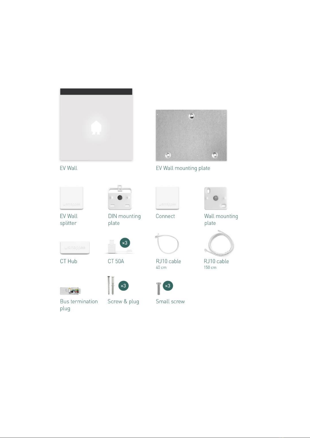
4. Components
Components included
Single phase

Smappee EV Wall –Installation manual - English
8
Three phase

Smappee EV Wall –Installation manual - English
9
Type 2 EV charging cable
In case of a fixed cable version the cable is supplied in a separate box.
1. 1 x 2.5 m or 8 m open-ended to type 2 EV charging cable
2. 8 m version: 1 x EV cable holder + 3 x screws + 3 x plugs
Identification label
The identification label of your charging station is located on the left inside of the EV Wall.
1. Manufacturer
2. Article number
3. Rating
4. QR code containing article number and serial number
5. Manufacturing date
6. Degree of protection
7. Serial number

Smappee EV Wall –Installation manual - English
10
5. Technical specifications
Feature
Description
EV Wall - Socket
EV Wall –Type 2 cable
Technical features
Charging capacity
Single or triple phase, 3.7 to 22 kW
Output power
1-phase or 3-phase, 230 V –400 V, 32 A
Charge mode
Mode 3 (IEC 61851)
Connection case
1 x Case B (Socket type 2)
1 x Case C (Fixed cable with
type 2 connector)
Integrated Residual Current
Monitor
Rated operating residual current detection : 6 mA DC / 30 mA AC
Metering
kWh meter compliant with IEC 62053-21
Interfaces & Connectivity
Information status
RGB LED
Session activation
Plug and charge, Scan QR code, Swipe RFID card, Smart EV
schedules
Connectivity
Ethernet 100BASE-T or Wi-Fi 2.4 GHz
Communication protocol
OCPP 1.6 JSON
Certifications and Standards
Product certification
CE
Standards
IEC 61851-1 (2017)
Environment
Enclosure material
Steel (housing), aluminium (front plate)
Enclosure rating
IP54 / IK10
Enclosure standard colours
RAL9016 (star white) + RAL7021 (black grey)
Operating temperature
-25 °C to 60 °C
Storage temperature
-25 °C to 80 °C
Relative humidity
0 % - 95 %, non-condensing
Maximum installation altitude
0 –2.000 m
Physical properties
Dimensions
300 x 300 x 110 mm
Weight (excluding packaging)
6.2 kg
6.8 kg (2.5 m cable) or 9.8 kg (8
m cable)
Charging cable length
N/A
1 x 2.5 m or 1 x 8 m
Mounting method
Wall

Smappee EV Wall –Installation manual - English
11
6. Preparing the installation
The first step is to prepare the physical installation of the EV Wall as described in this chapter.
Installation prerequisites
•Calculate the existing electrical load to find the maximum operating current for the charging
station installation. The Smappee EV Wall is equipped with 1 connector (socket or fixed cable)
which needs to be powered.
•Determine the voltage drop over the distance from the power supply panel to the charging
station installation. The voltage drop must not exceed 5 %. It is advised that the maximum
voltage drop be 3 %. The maximum wire gauge that can be fitted is 10 mm². Local regulations
may be applicable and can vary depending upon the region or country.
•Obtain all necessary permits from the relevant local authority.
•Refer to local wiring regulations to select the conductor sizes and use only copper conductors.
•Make sure that the installation area of the charging station is adequate for usability and
ventilation purposes.
•Use the correct tools and provide sufficient material resources and protection measures.
Route power supply
•The appropriate wire gauge of the supply cable depends on the power rating and distance
between the meter cabinet and the charging station. The voltage drop must not exceed 5%. It
is advisable to have a maximum voltage drop of 3%. The maximum wire gauge that can be
fitted is 10 mm².
•Route the power supply cables to the position where the charging station will be installed
together with a Cat 5/6 communication cable between the EV Wall and distribution panel.
•Make sure that there is at least 30 cm cable available at the location of the EV Wall to be able
to connect it easily internally.
The power supply enters the station at the bottom of the housing.
The Cat 5/6 communication cable also enters the charging station via the floor plate.
Ensure that you attach the RJ-45 connector only after inserting the cable into the EV Wall
housing.

Smappee EV Wall –Installation manual - English
12
The maximum power rating for each connector is specified in the table below.
Power per connector
Connection
Input current
Output current
3.7 kW
1-phase
1 x 16 A
1 x 16 A
11 kW
3-phase
3 x 16 A
3 x 16 A
22 kW
3-phase
3 x 32 A
3 x 32 A
Route communication cable
The EV Wall requires a communication cable between the EV Wall and the distribution panel where
the CT measurements and Connect gateway are placed. To do this, two twisted pairs of a Cat 5 or
Cat 6 networking cable are used. The Cat 5/6 cable should be connected between the PCB of the EV
Wall’s front plate and the splitter in the distribution panel. An RJ-45 connector (not supplied) should
be attached to both ends of the cable. Only attach the RJ-45 connector after inserting the cable into
the housing. The RJ-45 connector will not fit through the EV Wall’s cable gland!
Prepare the mounting
All Smappee EV Wall types are designed to be mounted on a wall.
When positioning the EV Wall, take into account that the power supply cables and communication
cable are entering the housing at the bottom through cable glands. The central M32 cable gland is
for the power supply, the M20 cable gland for the communication cable.

Smappee EV Wall –Installation manual - English
13
Tools (not included)
Screwdrivers
3mm Hex screwdriver
7mm socket wrench with extension bar
Multimeter and earth ground meter
Wire stripper and cutter.
Needle-nose pliers.
Ferrules crimper, for stranded power supply cables
Drill and rock drill diameter 10 mm.
Hammer
RJ45 crimping tool
Supplies (included)
3 x wall plugs and screws anchors (Ø 6 mm x 50 mm)
3 x M4 x 6 mm HEX screws
Supplies (not included)
CAT 5/6 cable and two RJ45 connectors for wired communication cable.
Power supply cables
Ferrules (10 mm²), for stranded power supply cables
32 A circuit breaker

Smappee EV Wall –Installation manual - English
14
7. Installation and activation
This procedure describes the required steps for the physical installation of the EV Wall.
CAUTION: Make sure it is not possible to connect the electric current during
installation. Put up caution tape and warning signs to mark the work areas. Make sure
no unauthorised people can enter the work areas.
Place the mounting plate in position
a. Use the mounting plate to mark the position of the screws on the wall where the EV Wall is to be
positioned. Make sure the mounting plate is positioned with the 2 insert holes on the bottom, as
depicted below.

Smappee EV Wall –Installation manual - English
15
b. Drill 3 holes of 10 mm diameter through the slots to a depth of 50 mm. Insert the supplied wall
plugs into the holes.
c. Attach the mounting plate to the wall with the supplied screws.
Smappee EV Wall –Installation manual - English
16
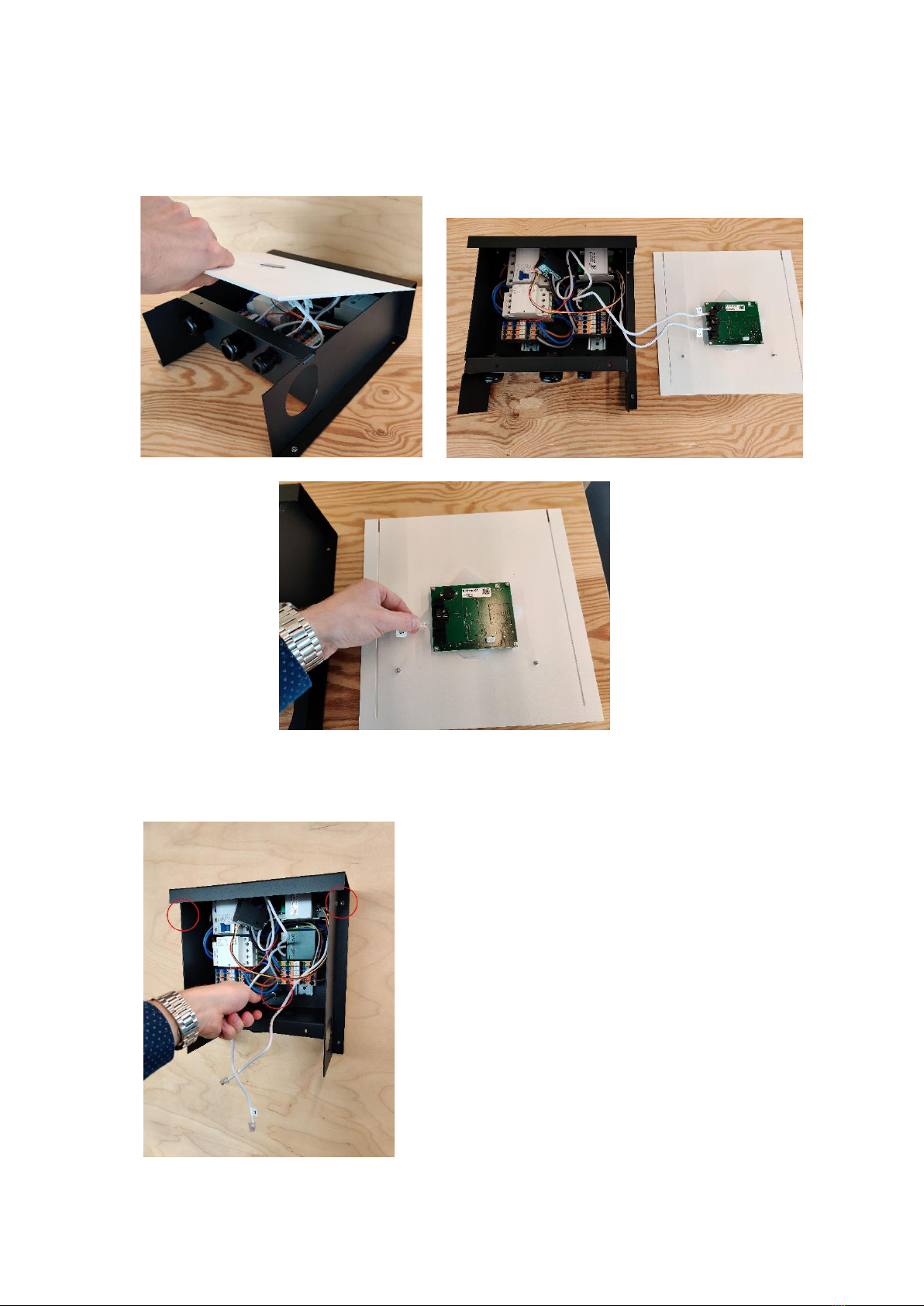
Place the EV Wall in position
a. Remove the front plate of the EV Wall and disconnect the communication cables. Safely put
aside the front plate to avoid damaging the PCB-board attached to it.
b. Attach the EV Wall housing to the mounting plate using the three supplied M4 x 6 mm HEX
screws.

Smappee EV Wall –Installation manual - English
17
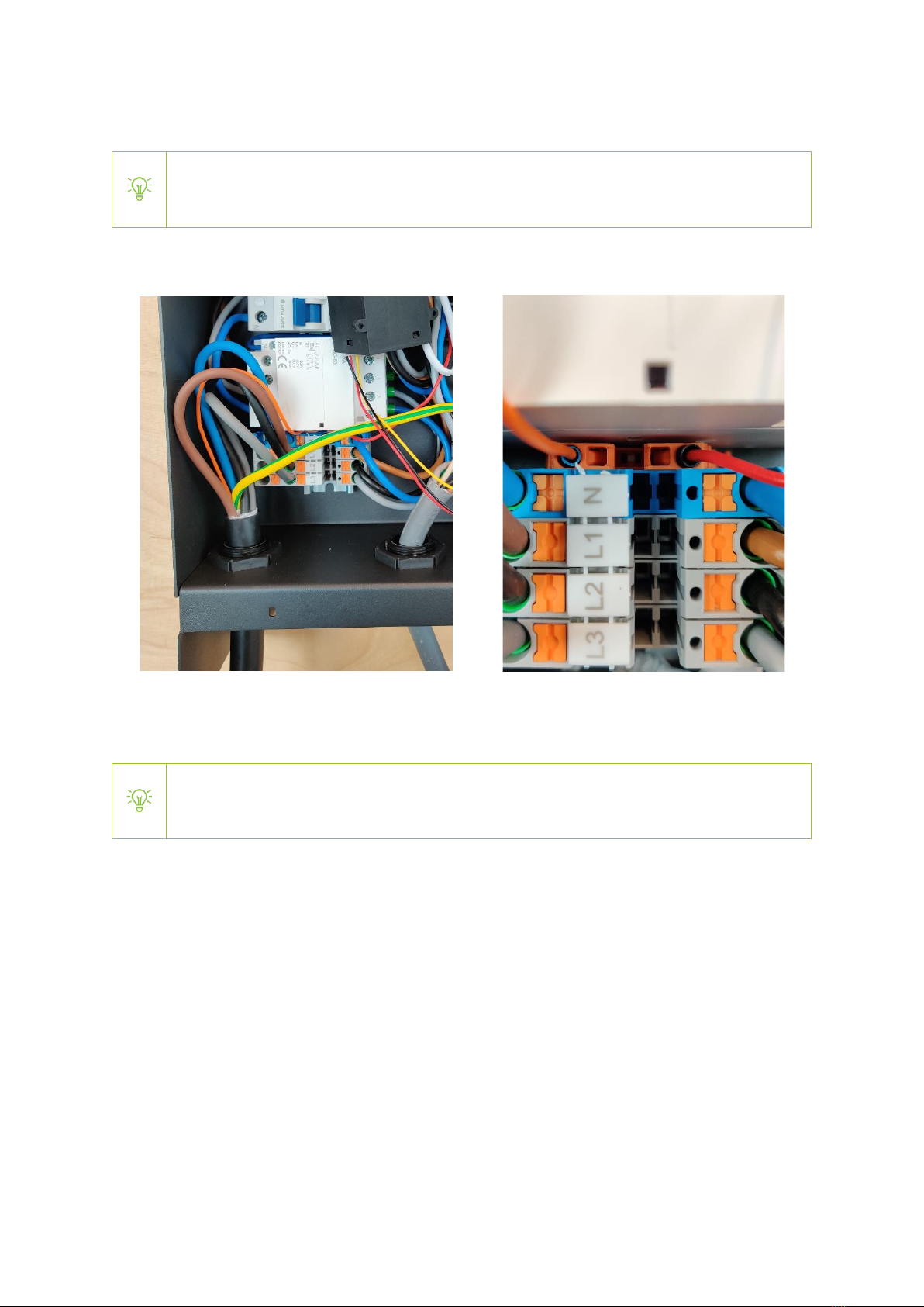
Power supply connection
a. Slide the power cable through the middle cable gland.
b. Cut the power supply cables to adequate length and add the ferrules to each conductor if
stranded cables are used.
c. Measure the resistance of the grounding circuit and make sure that it is within acceptable limits.
If necessary, install a grounding point closer to the charging station.
d. Connect each supply cable to the terminal block.
Smappee EV Wall –Installation manual - English
18
EV charging cable mounting (only fixed cable version)
This section is only relevant if the EV Wall comes with a fixed cable. If you have a socket
version, please continue to the next section.
a. Mount the fixed charging cable through the left M32 cable gland and mount the power supply
wires to the terminal block. Do not forget to connect the small orange CP data cable.
b. For the 8 m version, a separate cable holder is supplied and can be mounted on the wall nearby
the EV Wall.
The length of the fixed cable can be shortened if required. Cut the cable to its required
length and add ferrules (not supplied).

Smappee EV Wall –Installation manual - English
19
Installation in distribution panel
This chapter describes the installation of the Infinity components in the distribution panel. These
components enable overload protection & solar optimization supplied with the EV Wall.
The EV Wall package comes with the required Smappee Infinity components to be installed in the
distribution panel to measure the main feeder (total grid consumption) and single-phase solar
production. If three-phase solar is present, the EV Wall Solar Add-on can be purchased.
Depending on the EV Wall type (1-phase or 3-phase), the included Smappee Infinity components
varies:
oEV Wall 1-Phase:
▪1 x Connect
▪1 x CT Hub
▪3 x CT 50A (1x grid + 1x solar +1x EV measurement)
▪1 x EV Wall splitter
oEV Wall 3-Phase:
▪1 x Connect
▪1 x CT Hub
▪4 x CT 50A (3x grid + 1x solar measurement)
▪1 x Solid Core 3-Phase CT (EV measurement)
▪1 x EV Wall splitter
If additional CT measurements need to be added, standard Infinity hardware (CT Hubs and
CTs) can be purchased and installed in addition to the EV Wall components.
Always keep the Smappee Infinity installation guidelines in mind.
For installation of these components, please refer to the diagrams on the next page.
The main installation steps include:
a. Install the 32 A circuit breaker (not supplied) according to local regulations. In case of a three-
phase EV Wall: install the supplied solid-core CT together with the circuit breaker.
b. Install the CTs as indicated on the diagrams on the next page. Connect these to the supplied CT
Hub.
c. Install the Smappee Connect and EV Wall splitter. The Smappee Connect should be placed inside
or near the distribution panel. It requires a stable internet connection via Wi-Fi or Ethernet.
d. Connect the A- and B-bus cables as indicated on the diagram. Connect the Cat 5/6
communication cable to the RJ45 port of the splitter.
Ensure that the CT Hub(s) are connected to the A-port of the Smappee EV Wall splitter
and the Smappee Connect to the B-port of the Splitter. Also check that the Cat 5/6
communication cable is connected to the splitter and NOT to the Smappee Connect.

Smappee EV Wall –Installation manual - English
20
Connection diagram EV Wall –1-phase (1P+N)
Other manuals for EV Base
7
This manual suits for next models
47
Table of contents
Other Smappee Batteries Charger manuals

Smappee
Smappee EV Base Operator's manual

Smappee
Smappee EV Wall EVWL-332-BR-E-W User manual

Smappee
Smappee EV Base User manual

Smappee
Smappee EV One Home User manual

Smappee
Smappee EV Wall LITE User manual

Smappee
Smappee EV Base User manual

Smappee
Smappee EV One Home User manual

Smappee
Smappee EV Base User manual
Popular Batteries Charger manuals by other brands


Scanstrut
Scanstrut ROKK Wireless Edge installation instructions

as-Schwabe
as-Schwabe 65150 operating instructions

Bosch
Bosch Power Max Level 2 Installation and operating instructions

Nilfisk-Advance
Nilfisk-Advance SC1500 56104002 installation instructions

ABB
ABB HT577406 Operation manual

PATONA
PATONA PREMIUM Series manual