Smappee EV Wall EVWL-332-BR-E-W User manual

English –Version 1.0 –April 2023
Smappee EV Wall
LITE
Installation manual

Document Accuracy
The specifications and other information in this document were verified to be accurate and complete at the time of its publication. Due to
ongoing product improvement, this information is subject to change at any time without prior notice. For the latest information, see our
online documentation: https://www.smappee.com/downloads

Smappee –EV Wall Lite –Installation manual –English
Table of contents
1. Introduction ....................................................................................................4
2. Safety instructions...........................................................................................5
3. Models ............................................................................................................7
4. Components....................................................................................................8
5. Technical specifications.................................................................................10
6. Preparing the installation..............................................................................13
7. Installation and activation.............................................................................16
8. Using the EV Wall Lite ...................................................................................25
Declaration of conformity ...................................................................................29

Smappee –EV Wall Lite –Installation manual –English
1.Introduction
Thank you for purchasing this Smappee EV Wall Lite charging station for electric vehicles for charging
at home.
This installation and user manual tells you how to install and use the Smappee EV Wall Lite. We
advise you to read the contents of this manual carefully, to ensure a safe and proper installation.
Support
Only qualified electricians or equivalent may install the Smappee EV Wall Lite. If you have any
questions, please contact your service partner.
Please have the following information ready to speed up the process: article number and serial
number which you can find on the identification label of the charging station.
Should your local distributor be unable to help you, or you have a suggestion for us, you can contact
Smappee at: support@smappee.com.
Smappee n.v.
Evolis 104
8530 Harelbeke
Belgium

Smappee EV Wall Lite –Installation manual - English
5
2.Safety instructions
Safety warning
Fully read and follow the safety instructions below before you install, service or use your Smappee
EV Wall Lite. The installer must ensure that the charging station is installed in accordance with the
relevant national and local regulations.
Carrying out activities on this charging station without the relevant knowledge and qualifications can
lead to serious accidents and death. Only carry out tasks for which you are qualified and have been
fully instructed.
Incorrect installation, repairs or modifications can result in danger to the user and may void the
warranty and liability.
Safety precautions
CAUTION: Risk of electric shock.
CAUTION: Refer to the accompanying documentation whenever you see this symbol.
Please observe the following safety precautions to avoid potential electric shock, fire, or personal
injury:
•The charging station is intended exclusively for charging electric vehicles and, when installed
correctly, may be used by untrained individuals.
•Switch off electrical power supply to your charging station before installation or maintenance
work.
•Do not use the charging station if damaged / defective.
•Do not immerse the charging station in water or any other liquids.
•Do not expose the charging station to heat, flame or extreme cold.
•Do not attempt to open, repair, or service any parts. Contact Smappee or your service partner
for further information.
•Only use the charging station under the specified operating conditions.
•Do not allow children to operate a charging station.
•When a charging station is in use, adult supervision of any children present is required.
•While charging the charging cable must be completely unwound and connected to the electric
car without overlapping loops. This to avoid the risk of overheating the charging cable.
Maintenance
•Observe the maintenance schedule.
•Clean the outside only with a dry, clean cloth.
•Do not use abrasive agents or solvents.
•May not be carried out during rain or if air humidity exceeds 95%.

Smappee EV Wall Lite –Installation manual - English
6
Keeping order
•After charging store the charging cable properly so it does not present a tripping hazard.
•Make sure the charging cable cannot become damaged (kinked, compressed or driven over).
•Do not place any objects on the charging station.
Transport and storage
•Disconnect electrical power supply before removing the charging station for storage or
relocation.
•Only transport and store the charging station in its original packaging. No liability for damage
incurred will be accepted if the charging station is transported in non-standard packaging.
•Store the charging station in a dry environment within the temperature range specified in the
technical specifications.

Smappee EV Wall Lite –Installation manual - English
7
3.Models
Article no.
EAN
Description
EVWL-332-BR-E-W
5425036933989
EV Wall Lite White 3-Phase 22 kW Socket

Smappee EV Wall Lite –Installation manual - English
8
4.Components
Components included
Smappee EV Wall Lite –Installation manual - English
9
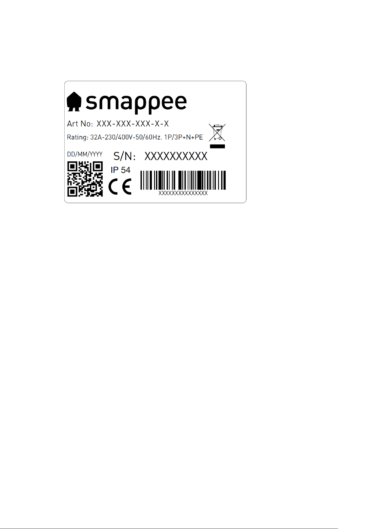
Identification label
The identification label of your charging station is located on the left inner side of the EV Wall Lite.
1. Manufacturer
2. Article number
3. Rating
4. Manufacturing date
5. QR code containing article number and serial number
6. Serial number
7. Degree of protection
8. EAN code

Smappee EV Wall Lite –Installation manual - English
10
5.Technical specifications
Feature
Description
Technical features
Charging capacity
Single or triple phase, 7.4 to 22 kW
Output power
1-phase or 3-phase, 230 V –400 V, 32 A
Charge mode
Mode 3 (IEC 61851)
Connection case
1 x Case B (Socket type 2)
Metering
kWh meter compliant with IEC 62053-21
Integrated Residual Current
Protection
Rated operating residual current detection: 6 mA DC.
Supported power systems
TN-C, TN-C-S, TT, IT*
*Caution: not all vehicles support the IT system. In this case or
with 3x230V charging, a voltage transformer may be required.
Grounding
TN system: PE wire
TT system: Independently installed ground electrode < 100 Ohm
spreading resistance
IT system: connected to a shared reference (common earth) with
other metal parts
Rated voltage (Un)
230 V –400 V
Rated insulation voltage (Ui) of
a circuit
500 V
Rated impulse withstand
voltage (Uimp)
4 kV
Rated frequency (fn)
50 Hz / 60 Hz
Rated current (Ina)
32 A
Rated current (Inc) of a circuit
32 A
EMC classification
Class B
Connection method
AC, permanently connected
Required external protection
2P (single-phase) or 4P (three-phase) breaker of max. 32 A, type
B or C
30 mA AC RCD type A or B (according to local regulations)
Interfaces & Connectivity
Information status
RGB LED
Session activation
Plug and charge, Scan QR code, Swipe RFID card
Connectivity
Ethernet 100BASE-T, Wi-Fi 2.4 Ghz
Communication protocol
OCPP 1.6 JSON, ready for update to OCPP 2.0

Smappee EV Wall Lite –Installation manual - English
11
Certifications and Standards
Product certification
CE
Standards
IEC 61851-1 (2017)
Environment
Enclosure material
Magnelis (housing), aluminium (front plate)
Enclosure standard colours
RAL9016 (star white) + RAL7021 (black grey)
Protection degree
IP 54
Mechanical impact protection
IK10
Pollution degree
3
Electrical safety class
I
Stand-by use
LED brightness 0%: 2 W
LED brightness 100%: 5 W
Environmental conditions
Indoor and outdoor use
Operating temperature
-25 °C to 40 °C
Storage temperature
-25 °C to 60 °C
Relative humidity
0 % –95 %, non-condensing
Maximum installation altitude
0 –2.000 m
Access
Locations with restricted and non-restricted access
Physical properties
Dimensions
300 x 300 x 110 mm
Weight (excluding packaging)
6.2 kg
Charging cable length
N/A
Supply line connection
Terminal block, flexible conductors up to 6 mm² or solid
conductors up to 10 mm²
Stationary / moveable
Fixed installation
External design
Enclosed assembly
Mounting method
Wall

Smappee EV Wall Lite –Installation manual - English
12
The operating temperate assumes the ambient temperature of a product delivered in the
default enclosure colours RAL9016 (star white) + RAL7021 (black grey). Direct exposure to
sunlight may have an adverse effect on the temperature range.
If the product is exposed to lower or higher ambient temperatures, continuous operation
cannot be guaranteed. If temperatures exceed the maximum values, the charging station
will automatically decrease the charging current to decrease the internal temperature of
the charging station.
This stabilises the internal temperature and makes it less likely that a charging session will
be unexpectedly paused.
If the product is directly exposed to sunlight, the automated temperature management
may automatically start below the maximum ambient temperature. Therefore, wherever
possible, avoid exposing the charging station to direct sunlight.
Where products are exposed to the elements of nature, the enclosure can be subject to
gradual aging of the material, which can result in product discolouration over time.
Therefore, wherever possible, place the product in a sheltered place to optimise the life of
the materials.

Smappee EV Wall Lite –Installation manual - English
13
6.Preparing the installation
The first step is to prepare the physical installation of the EV Wall Lite as described in this chapter.
Installation prerequisites
•Calculate the existing electrical load to find the maximum operating current for the charging
station installation. The Smappee EV Wall Lite is equipped with 1 connector which needs to be
powered.
•Obtain all necessary permits from the relevant local authority.
•Refer to local wiring regulations to select the conductor sizes and use only copper conductors.
•Make sure that the installation area of the charging station is adequate for usability and
ventilation purposes.
•Use the correct tools and provide sufficient material resources and protection measures.
Power supply
•The appropriate wire gauge of the supply cable depends on the power rating and distance
between the meter cabinet and the charging station. The voltage drop must not exceed 5%. It
is advisable to have a maximum voltage drop of 3 %.
•The maximum wire gauge that can be fitted is 6 mm² in case of flexible conductors or 10 mm²
when solid conductors are used.
•The power supply must be protected against short-circuiting and over-current with an
individual B or C circuit breaker with a current rating of maximum 32 A (or otherwise in
compliance with local standards and regulations). An RCD of type A or B (according to local
regulations) with rated residual operating current of 30 mA must also be installed. A charging
station connector must always be installed on a dedicated power circuit.
•When the power supply and the charging station are part of a TN-S system, the station must
be grounded via the main distributor.
•Route the power supply cables to the position where the charging station will be installed
together with an Ethernet cable for the internet connection (if applicable).
•Make sure that there is at least 30 cm cable available at the location of the EV Wall Lite to be
able to connect it easily internally.
•Local regulations may be applicable and can vary depending upon the region or country.
The power supply enters the station at the bottom of the housing through the middle
cable gland.
The Cat 5/6 Ethernet cable also enters the charging station via the bottom of the housing.
Ensure that you attach the RJ-45 connector only after inserting the cable into the EV Wall
Lite housing.

Smappee EV Wall Lite –Installation manual - English
14
The maximum power rating for each connector is specified in the table below.
Power per connector
Connection
Input current
Output current
7.4 kW
1-phase
1 x 32 A
1 x 32 A
22 kW
3-phase
3 x 32 A
3 x 32 A
Route Ethernet cable
The EV Wall Lite requires a stable internet connection via Ethernet. An RJ-45 connector (not
supplied) should be attached to the end of the cable. Only attach the RJ-45 connector after inserting
the cable into the housing. The RJ-45 connector will not fit through the EV Wall Lite cable gland!
Prepare the mounting
The Smappee EV Wall Lite is designed to be mounted on a wall.
When positioning the EV Wall Lite, take into account that the power supply cables and Ethernet
cable are entering the housing at the bottom through cable glands. The central M32 cable gland is
for the power supply, the M20 cable gland for the Ethernet cable.

Smappee EV Wall Lite –Installation manual - English
15
Tools (not included)
Screwdrivers
3mm Hex screwdriver
7mm socket wrench with extension bar
Multimeter and earth ground meter
Wire stripper and cutter
Needle-nose pliers
Ferrules crimper, for stranded power supply cables
Drill and rock drill diameter 10 mm
Hammer
RJ45 crimping tool
Supplies (included)
3 x wall plugs and screws (Ø 4.8 mm x 50 mm)
3 x M4 x 6 mm HEX screws
Supplies (not included)
CAT 5/6 ethernet cable and RJ45 connector for internet access
Power supply cables
Ferrules (6 mm²), for stranded power supply cables
32 A circuit breaker
30 mA RCD Type A or B

Smappee EV Wall Lite –Installation manual - English
16
7.Installation and activation
This procedure describes the required steps for the physical installation of the EV Wall Lite.
CAUTION: Make sure it is not possible to connect the electric current during
installation. Put up caution tape and warning signs to mark the work areas. Make sure
no unauthorised people can enter the work areas.
CAUTION: The electric system must be entirely disconnected from every power source
prior to performing installation or maintenance work. Make sure it is not possible to
connect the electric current during installation. Put up caution tape and warning signs
to mark the work areas. Make sure no unauthorised people can enter the work areas.
CAUTION: The charging station contains electric components that may still contain
electrical charge after being disconnected. Wait at least 10 seconds after disconnection
before commencing work.
CAUTION: Adaptors or conversion adaptors and cord extension sets are not allowed to
be used.
Place the mounting plate in position
a. Use the mounting plate to mark the position of the screws on the wall where the EV Wall Lite is
to be positioned.
b. Make sure the mounting plate is positioned with the 2 insert holes on the bottom and that it
hangs level.
c. Drill 3 holes of 10 mm diameter through the slots to a depth of 50 mm. Insert the supplied wall
plugs into the holes.
d. Attach the mounting plate, with the 3 bulges facing the wall, to the wall with the supplied
screws, as depicted below.

Smappee EV Wall Lite –Installation manual - English
17
Place the EV Wall Lite in position
a. Untighten the two M4 nuts on the back of the front plate and remove the front plate of the EV
Wall Lite. Safely put aside the front plate to avoid damaging the PCB-board attached to it.
b. Attach the EV Wall Lite housing to the mounting plate using the three supplied M4 x 6 mm HEX
screws.
Smappee EV Wall Lite –Installation manual - English
18
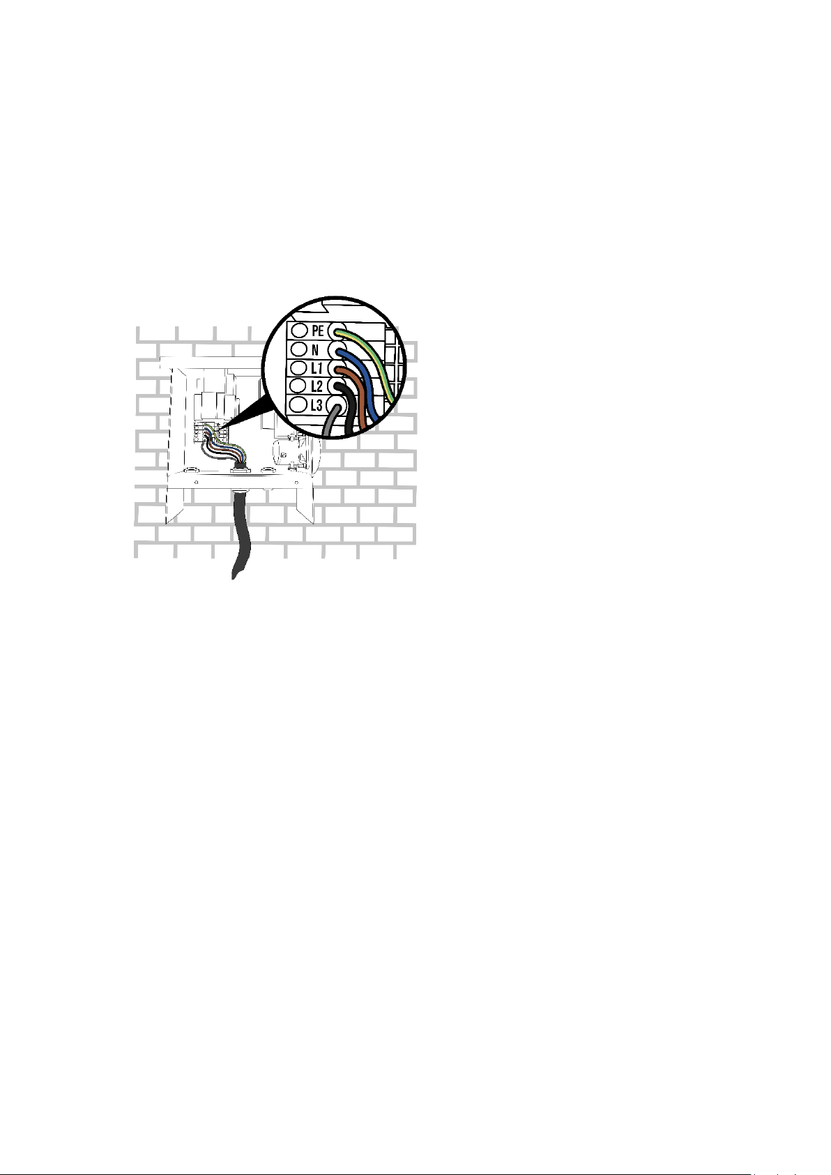
Power supply connection
a. Slide the power cable through the middle cable gland.
b. Cut the power supply cables to adequate length and add the ferrules to each conductor if
stranded cables are used.
c. Measure the resistance of the grounding circuit and make sure that it is within acceptable limits.
If necessary, install a grounding point closer to the charging station.
d. Connect each power supply cable to the terminal block.
If you have a single-phase power supply, only the L1, N and PE wires are connected.

Smappee EV Wall Lite –Installation manual - English
19
IMPORTANT notes for 3P (3 x 230 V) –Delta topology
This section is only relevant if you have a delta grid topology. This is only found in some
parts of Belgium and Norway. If this is not applicable, you can skip this section.
When an EV Wall Lite is installed in a residential installation with a 3P (3 x 230 V) Delta grid
connection, some additional requirements need to be taken into account. You can verify whether
you have this topology by checking the grid connection to see if the following are true:
•There is no neutral wire.
•The voltage between two phases is approximately 230 V.
•The voltage between a phase and earth is approximately 130 V.
Some EVs are not compatible with this type of grid connection due to a built-in security in the EV.
Contact your EV manufacturer for more information.
The security feature that some EVs have is a voltage check between the phase that is connected as
neutral and the ground. If this is not 0 volts, the car won’t charge. The presence of this security
feature may vary for each manufacturer and for each model.
As there is no neutral wire available in this topology, the L3 will be used as neutral. In this case, some
EVs will be able to charge dual phase (using both L1 and L2) and some will only charge single phase.
In practice, this may limit the maximum charging power. This again varies for each EV manufacturer
and each model.
If your EV is not compatible with this grid topology, or if you would like to achieve higher charging
power than what is possible on a delta grid topology, you can install a transformer. This transformer
will convert the 3 x 230 V delta topology to a standard 3 x 400 V + N star topology.

Smappee EV Wall Lite –Installation manual - English
20
Without transformer
If you are connecting the charging station directly to the 3 x 230 V delta grid, without transformer,
please refer to the diagrams below.
As depicted, the L3 connector is left empty. The L3 power supply cable is connected to the N
connector block.
We highly recommend that you test compatibility with the customer’s EV during
installation. If you have connected the EV Wall Lite as shown above but the EV will not
charge, you can try to disconnect the L2 cable going to the socket. Do not disconnect the
L2 of the power supply cable!
With transformer
If a transformer is used to convert the 3 x 230 V delta connection to a standard 3 x 400 V star with
neutral, then the charging station’s power supply can be connected as usual. Please refer to the
pictures on previous pages for this.
This manual suits for next models
1
Table of contents
Other Smappee Batteries Charger manuals


