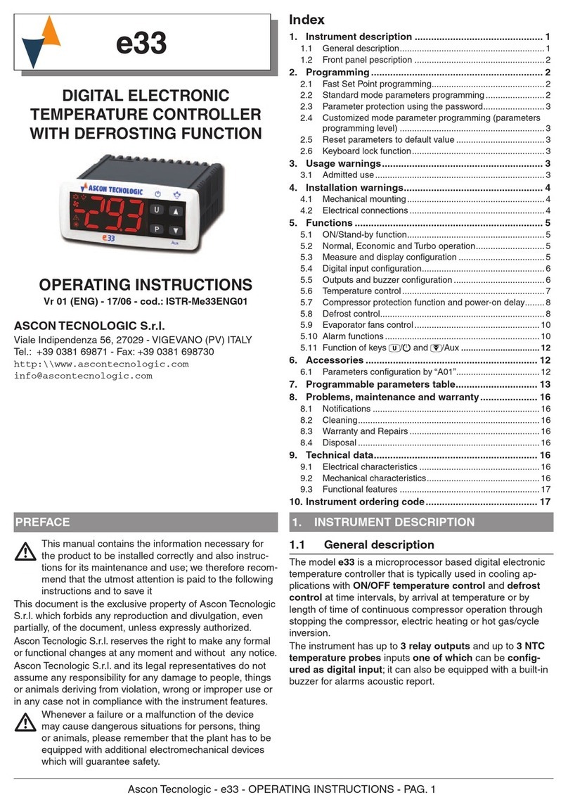
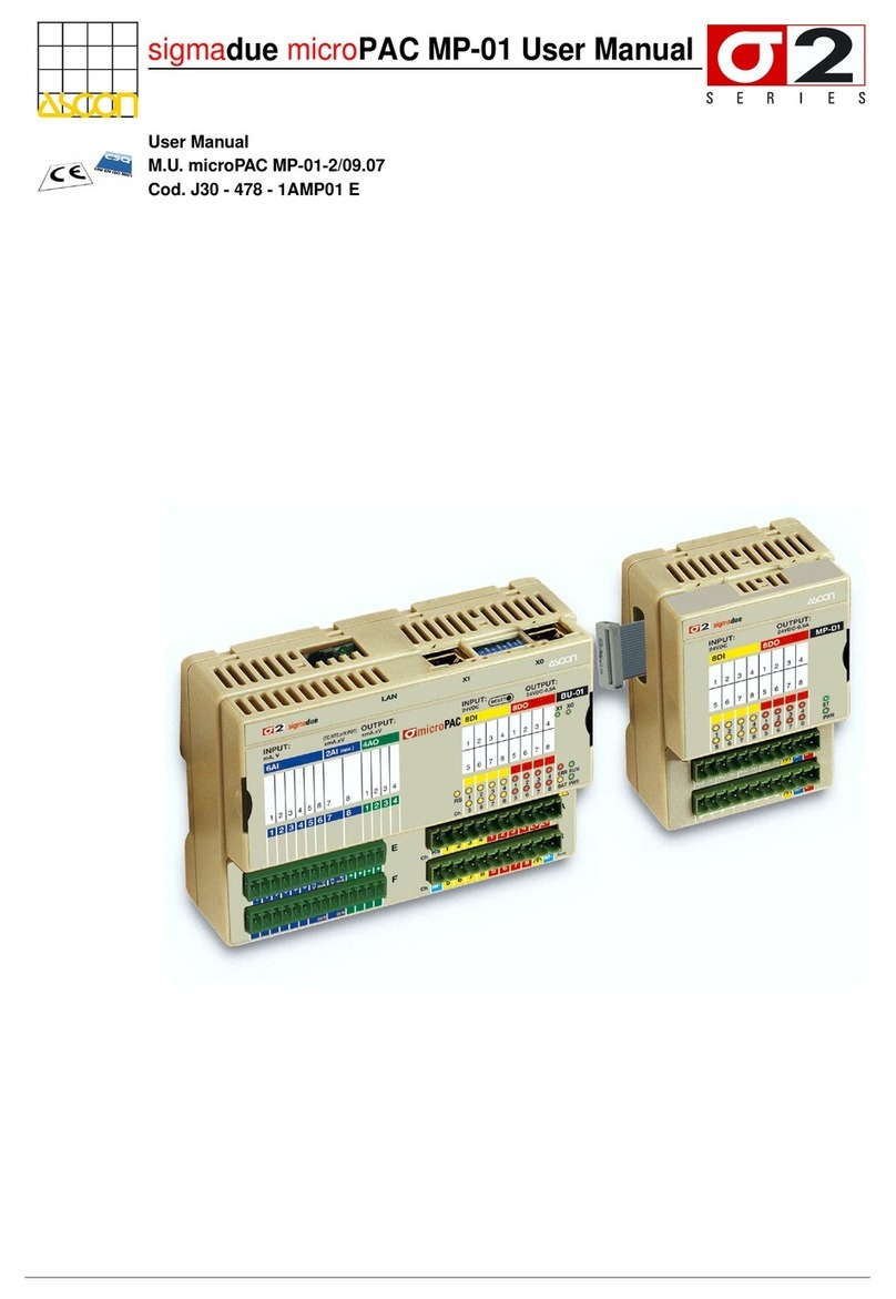
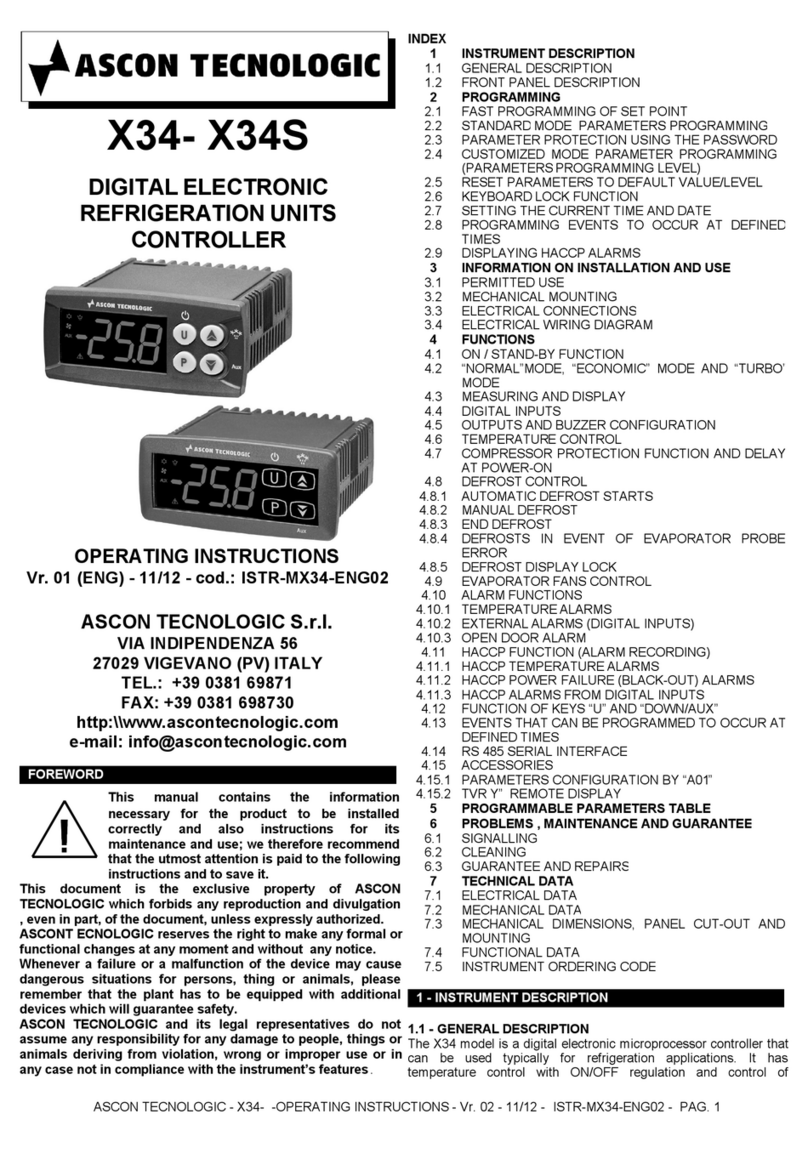
ascon QP Series User manual

ASCON TECNOLOGIC S.R.L.
viale Indipendenza, 56 - 27029 Vigevano (PV) Italy
tel. +39 0381 69 871 - fax +39 0381 69 87 30
MILAN OFFICE
via Falzarego, 9/11 - 20021 Baranzate (MI) Italy
tel. +39 02 33 33 71 - fax +39 02 3504 243
P.I. e C.F. 02374940183 - Cap. Soc. 1.000.000,00 i.v.
R.E.A. PV - N. 268075 - P.I. e C.F. 02374940183
DICHIARAZIONE CE DI CONFORMITÀ
EU KONFORMITÄTSERKLÄRUNG
EC DECLARATION OF CONFORMITY
UE DECLARATION DE CONFORMITE
Noi/
Wir/We/Nous:
Ascon Tecnologic S.r.l. (Nome del fabbricante)
(Name der fabrikant)(Manufacturer’s name)(Nom du fabricant)
via Indipendenza 56, 27029 Vigevano (PV) (Indirizzo)
(Anschrift)(address)(adresse)
dichiariamo sotto la nostra responsabilità che il prodotto
/erklären in alleiniger Verantwortung, dass das Produkt/
declare under our sole responsibility that the product/déclarons sous notre seule responsabilité que le produit
Regolatori Serie QF, QD e QP – Regler Serie QF, QD und QP –
QF, QD and QP Series controllers – Régulateurs Série QF, QD et QP
(Nome, tipo o modello)
(Bezelchnung, Typ oder Modell)(Name, type or model)(Nom, type ou modèle)
al quale questa dichiarazione si riferisce è conforme alle seguenti Direttive CE:
auf die sich diese Erklärung bezieht, in Übereinstimmung mit den folgenden EG-Richtlinien:
to which this declaration relates, following the provisions of Directives:
auquel se réfère cette déclaration, conformément aux dispositions des Directives:
Direttiva del Consiglio delle Comunità Europee 2004/108/EC del 15 dicembre 2004 per il riavvicinamento delle legislazioni degli Stati membri relative alla compatibilità elettromagnetica.
Richtline des Rates 2004/108/EC vom 15 dezember 2004 zur Angleichung der Rechtsvorschriften der Mitgliedstaaten über die Elektromagnetische Verträglichkeit.
Council Directive 2004/108/EC dated December 15, 2004 on the approach of the laws of member States relating the electromagnetic compatibility.
Directive du Conseil de la Communauté Européenne
2004/108/EC du 15 decembre 2004
pour le rapprochement des législations des Etats membres concernant la compatibilité éléctromagnétique.
Direttiva del consiglio delle Comunità Europee 2006/95/EC del 12 dicembre 2006 per il ravvicinamento delle legislazioni degli Stati membri relative al materiale elettrico destinato ad essere
adoperato entro taluni limiti di tensione.
Richtline des Rates 2006/95/EC vom 12 dezember 2006 zur Angleichung der Rechtsvorschriften der Mitgliedstaaten betreffend elektrische Betriebsmittel zur Verwendung innerhalb bestim-
mter Spannungsgrenzen.
Council Directive 2006/95/EC dated December 12, 2006 on the harmonisation of the laws of Member States relating to electrical equipment for use within certan voltage limits.
Directive du Conseil des Communautés Européennes 2006/95/EC du 12 decembre 2006 pour le rapprochement des législations entre Etats membres au sujet du matériel électrique destiné
à être utilisé dans certaines limites de tension.
(Titolo e/o numero e data di pubblicazione delle norme o di altri documenti normativi)
(Titel und/oder Nummer sowie Ausgabedatum der Normen oder der anderen normativen Dokumente)
(Title and/or number and date of issue of the standards or other normative documents)(Titre et/ou numéro et date de publication des normes ou autres documents normatives)
e quindi è conforme alle seguenti norme o altri documenti normativi:
und somit in Einklang mit den folgenden Normen oder normativen Dokumenten übereinstimmt:
and therefore it is in conformity with the following standards or other normative documents:
et il est donc conforme aux normes ou autres documents normatives:
EN 61000-6-3:2007
Compatibilità elettromagnetica - Norma generica sull’emissione – Ambienti residenziali.
Elektromagnetische Verträglichkeit - Fachgrundnorm Störaussendung – Wohnumgebungen.
Electromagnetic compatibility - Generic emission standard – Residential environment.
Compatibilité électromagnétique - Norme générique immunité - Environnement résidentiel.
EN 61000-6-4:2007
Compatibilità elettromagnetica - Norma generica sull’emissione - Ambiente industriale.
Elektromagnetische Verträglichkeit - Fachgrundnorm Störaussendung - Industriebereich.
Electromagnetic compatibility - Generic emission standard - Industrial environment.
Compatibilité électromagnétique - Norme générique émission - Environnement industriel.
EN 61000-6-2:2005
Compatibilità elettromagnetica - Norma generica sull’immunità - Ambiente industriale.
Elektromagnetische Verträglichkeit - Fachgrundnorm Störfestigkeit - Industriebereich.
Electromagnetic compatibility - Generic immunity standard - Industrial environment.
Compatibilité électromagnétique - Norme générique immunité - Environnement Industriel.
EN 61010-1:2001
Prescrizioni di sicurezza per apparecchi elettrici di misura, controllo e per utilizzo in laboratorio – Prescrizioni generali. Categoria d’installazione II, Grado di inquinamento 2.
Sicherheitsbestmmungen für elektrische Meß-,Steuer-, Regel- und Laborgeräte - Allgemeine Anforderungen Verschmutzungsgrad 2 Überspannungskategorie II.
Safety requirements for electrical equipment for measurement, control and laboratory use - General requirements Installation category II, Pollution degree 2.
Régles de sécurité pour appareils électriques de mesurage de régulation et de laboratoire - Presciptions générales, catégorie d’installation II, degré de pollution 2.
Vigevano, Aprile 2011 Clemente Bommarito
(Luogo e data)
(Ort und Datum der Ausstellung)
(Nome e firma della persona autorizzata)
(Name und Unterschrift odel gleichwertige
(Place and Date of issue)(Lieu et date) Kannzeichnug des Befurgten)(Name and signature of authorized person)
(Nom et signature du signataire autorisé)

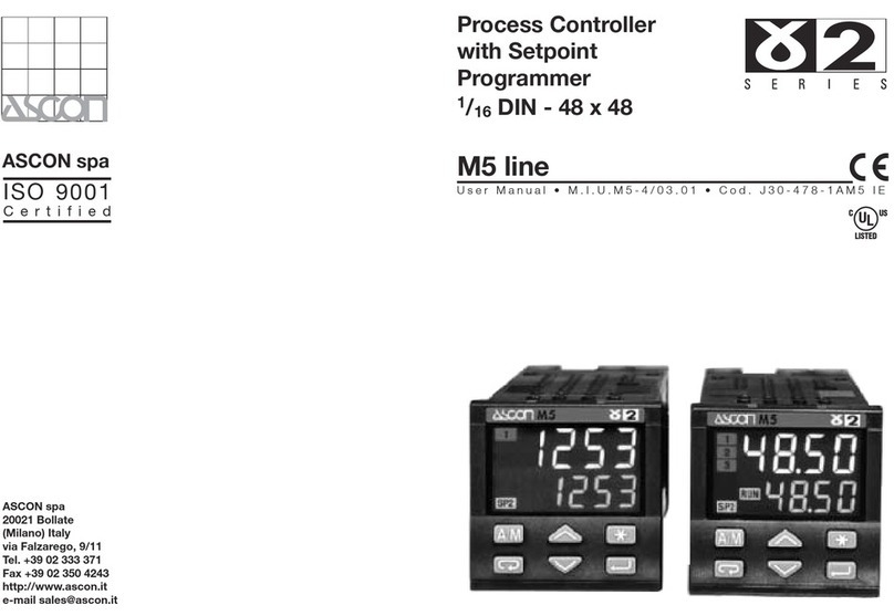
Process Controller
1/4 DIN - 96 x 96 mm
Dual-loop - QD line
Controller - Programmer QP line
B.T. 02.16.95E
E
ASCON spa
20021 Bollate - (Milano) Italy - Via Falzarego, 9/11 - Tel. +39 02 333 371 - Fax +39 02 350 4243
Certified ISO 9001
The Hardware
Package
2 analog inputs, 1 remote set
input, 3 logic inputs, 2 control
outputs, 4 auxiliary relay outputs,
2 logical outputs, 1
retransmission and RS485
Modbus-Jbus communication.
Complete
Configurability
From the keyboard and via serial
connection, using a guided
menu, you can choose the
operation mode, the control
algorithm, the input and output
types, the Set points. You can
also insert all parameters.
FUZZY Intelligence
In combination with the PID
algorithm and an advanced
tuner, this always guarantees a
smooth and precise regulation,
even for critical processes.
High Security
Guaranteed: by the ISO9000
certificate for planning and
construction quality; by the CE
brand for security and immunity
from disturbances; and by 3
levels of accessibility to
parameters.
These 96x96 DIN controller-
programmers are particularly
suitable for the control of
industrial processes.


QP_1-3 (Convertito)-2 9-05-2000 23:15 Pagina 1
Colori compositi
C M Y CM MY CY CMY K
ASCON spa
Regolatore-Programmatore
Multi-ingresso, Multi-uscite,
Multi-funzioni
Serie QP
ISTRUZIONI PER L'USO
INSTRUCTION MANUAL
M.I.U.QP - 1/96.06
Cod. J30 - 304 - 1AQP-IE
Programmer Process Controller
Multi-input, Multi-output
Multi-functions
Series QP

QP_1-3 (Convertito)-2 9-05-2000 23:15 Pagina 2
Colori compositi
C M Y CM MY CY CMY K
1
18
17
21
16
33
16 34 35
567589510 11
17
18 19
16
19
16
22 23 24
IDENTIFICATION OF MODEL page 2
DIMENSIONS AND INSTALLATION page 3
ELECTRICAL WIRING page 4
KEYS AND DISPLAYS FUNCTIONS page 12
CONFIGURATION page 14
PROGRAMMING PROCEDURE page 20
Parameterization page 21
Parametr description page 25
PROGRAMMABLE SET POINT page 28
Programme loading and/or modification page 31
Operating phases page 34
OPERATING INSTRUCTIONS see enclosed leaflet
TECHNICAL DATA page 39
PRGM PROGRAMMING GUIDE see enclosed leaflet
SERIAL COMMUNICATIONS (See MIU-CS) separately supplied
INDEX
E
READING INSTRUCTION
To better read and understand this manual please note the following:
Electrical wiring
Configuration
Parameterization
Programmable Set Point

QP_1-3 (Convertito)-2 9-05-2000 23:15 Pagina 3
Colori compositi
C M Y CM MY CY CMY K
1
2
QP - 3001
Model code: QP
Power supply
Serial communications RS485
Auxiliary analog output Y6
Programmable Set point
IDENTIFICATION OF MODEL
Thank you for choosing an ASCON controller.
The QP series controllers can be used as programmer controllers. They are
available with two main versions: the first with "Standard Set point" (Local/Rem/3
memorized S.p.), the second with "Programmable Set point" as an option
(e.g. QP-3…1)
They are fitted with AUTO-TUNE, as auxiliary for sistem start-up, and serial
communications for introduction into a distributed control network.
They are complete because all possible variables are always present.
Configuration of the instrument permits determination of the operating mode
according to the required application.
1.1 Identification of model
Model code : QP
100…240V 50/60 Hz 3
16…28V 50/60 Hz and 20…30V dc 5
None 0
RS485 Modbus - Jbus 3
None 0
0/4…20mA, 0/1…5V, 0…10V 1
E
Serial communications (option)
Power supply
Y6 auxiliary output (option)
None 0
Provided (16 Prgm.s, 255 Segm.s) 1
Programmable Set point (option)

QP_1-3 (Convertito)-2 9-05-2000 23:15 Pagina 4
Colori compositi
C M Y CM MY CY CMY K
2
3
154,5
91,5
96
96
92+0.8
112,5
135
model :
serial n.:
supply :
1
°F
2
3
4
5
°C
Y
W
SV
X
PV
REM
F
W/SV
A/M
MV
MAN
SCI
AT
RUN
HLD
W
SG
PID
SERIES
QD
1
°F
2
3
4
5
°C
Y
W
SV
X
PV
REM
F
W/SV
A/M
MV
MAN
SCI
AT
RUN
HLD
W
SG
PID
SERIES
QF
%
HR%
mV
V
A
kW
psi
Bar
°F
MPa
l/m
m
3
/h
Nm
3
/h
CO%
O
2
%
m
rh
Pa
kPa
mA
°C
DIMENSIONS AND INSTALLATION
Protection gaskets
2.1 Overall dimensions
2.2 Panel installation
2.3 Front protection IP67
14 92+0.8
B •Fixing with clamps
A •Panel fitting
C •plate for engineering units
100 min
115 min
with protection IP67
Advised thickness 7mm
Locking
screws
Seal clamps
fittings
ENVIROMENT:
Temperature: 0…50 °C
Humidity : 30…85UR%
Install away from:
•heat sources
•corrosive gases
•dusty environments
if different from
°C, remove and
apply plate with
requested unit.
label supplied
Cross
screw-driver
mod. F10-435-2A101
100 min.
150 min
with protection IP67
EE

QP_1-3 (Convertito)-2 9-05-2000 23:15 Pagina 5
Colori compositi
C M Y CM MY CY CMY K
3
4
A1
A2
A3
A4
A5
A6
A7
B1
B2
B3
B4
B5
C1
C2
C3
C4
C5
C6
C7
C8
D2
D3
D4
D5
D6
D7
D8
max.6 max.6
7
BAC
ED
C
A
C
D
E
B
B6
B7
B8
B
Power supply and output channels
Channel for low level signal conductor
with fork terminals
Single out
supply line
from power line
Keep away from
teleruptors,
electromagnetic
contactors and
powerful motors
Keep away from
power groups,
in particular if
with phase control
ELECTRICAL WIRING
A •Terminal board
B •Effecting the connections
3.1 Precautions and advised conductor course
A. Precautions B. Advised conductor course
27 screw terminals M3.5
3 gilded terminals for imput signals
Cold joint
compensation
thermometer
Wiring protection
plate
N°2 wires N°2 wires
with eyelet terminals
cable section
0,25÷2,5 mm2
AWG 22÷14
Although this controller is designed to resist the heaviest disturbances
present in industrial environments (as per CE mark), it is advised to
keep to the following precautions:
Serial
communications
Analogic
outputs
Power supply
Outputs
Logic inputs
outputs and
analogic signals
EE
Preferential

QP_1-3 (Convertito)-2 9-05-2000 23:15 Pagina 6
Colori compositi
C M Y CM MY CY CMY K
3
5
24V
A1
A2
A3
A4
A5
A6
A7
B1
B2
B3
B4
B5
W REMINPUT 1
DIGITAL INPUTS
mA/V TC
3
2
1C1
C2
C3
C4
C5
C6
C7
D2
D3
D4
D5
D6
D7
D8
OUTPUTS
RS485POWER
C8
Y1C
C
N
L
V
OUT
Y6
Y3
Y2
Y1▲/Y5
0%
100%
5•
3•
2•
4• 6•
1•
6•
8•
D7
D8
N
L
V
7•
B6
B7
B8
DIGITAL OUTPUTS
Y1▼/Y4
9•
10•
A6
A7
A •For Thermocouples
J-L-T-K-S-R-B-N-E-W
ELECTRICAL WIRING
switching type with double isolation
Standard:
100…240Vac
-15 +10% (250 Vac max)
or:
24Vac - 24Vdc -15 +10%
Absorbed power 5 VA max
•Respect polarities
•For eventual extensions,
use a compensated
cable suitable for the type
of used thermocouple
•The eventual screen is
well earthed at only one
end
Wiring diagram
1• Single power supply
2• "X" measurement inputs
tra
Relay outputs,
combined to the
terminals C1/C2
and C2/C3, can
be configured
as auxiliary
output Y4 and
Y5 (alarms) only
if they are not
used as main
control output.

QP_1-3 (Convertito)-2 9-05-2000 23:15 Pagina 7
Colori compositi
C M Y CM MY CY CMY K
3
6
X2
A5
A6
A7
B
A
B
Rj
A6
A7
24V
A6
A7
B5
Rj
XmA
24V
A6
A7
B5
Rj
XmA
ELECTRICAL WIRING
•For 3-wires connection, use cables
of same section (min. 1mm2)
Line 20Ωmax. for wire
•For 3-wires connection, use cables
of adeguate section (min.1,5mm2)
Note: with a 15m probe-controller
distance and a 1,5mm2section
cable, the error is about 1°C.
B •For RTD Pt100
C.1 •For 2 wires transmitter
auxiliary power supply
for transmitter
24 Vdc ±10%
30mA max
C •Continuous mA, Volt
C.2•For 3 or 4 wires transmitter
auxiliary power supply
for transmitter
24 Vdc ±10%
30mA max
Internal Rj = 30Ωper mA
Internal Rj = 10MΩper mV
Internal Rj = 10KΩper Volt
transmitters
2 •"X" measurement input (continued)
transmitters
For 2 wires connection a
jumper among A5 and A6
terminals must be done

QP_1-3 (Convertito)-2 9-05-2000 23:15 Pagina 8
Colori compositi
C M Y CM MY CY CMY K
3
7
A3
A4
Rj
B1
B2
B3
B4
C3
C2
C1
com.
A1
A2
A3
0%
100%
0%
100%
A3
A4
1
16
7
6
5
432
ELECTRICAL WIRING
Current
0/4…20mA
Internal Rj = 30Ω
Voltage
1…5V, 0…5V, 0…10V
Internal Rj = 300 KΩ
NOT galvanically isolated
When the external logic input
is ON (maintained closed
contact), the relevant function
is operating.
When the external logic input
is OFF (maintained opened
contact), the relevant function
is not operating.
(see page 19)
From 100Ωto 10KΩ
Useful
stroke Total
stroke
Remote set point
mA, Volt
Isolated
contact NPN o.c.
output TTL o.c.
output
3•Auxiliary input
4 •Logic inputs
5 •Input feedback potentiometer (servomotors)
E
Astabilizedexternalvoltagesourse (max
5Vdc) allows to select one of the
memorized Prgm.s.
Each Prgm has to be selected by a
different voltage value as follows:
(E.g. Prgm 8 = 2,5 Vdc).
With Vin = 0 the selection is inhibited.
Vin = N°Prgm
3.2
5Vdc
Wiring
Diagram
On Programmable Set point version these terminals must be used as Prgm selection input.
On Standard Set point version these terminals must be used as Remote Set point input.

QP_1-3 (Convertito)-2 9-05-2000 23:15 Pagina 9
Colori compositi
C M Y CM MY CY CMY K
3
8
C1
C2
V
C1
C2
C3
V
M
D5
D6
V
D5
D6
Y1▲Y1C
Y1▲
Y1▼
Y1C
C1
C2
C3
V
C1
C2
VD5
D6 V
Y1▲
Y1▼
Y1▲Y1C
ELECTRICAL WIRING
increase
decrease
Three position with two interlocked
contacts (increase, stop, decrease)
load
contactor or
static relay
Output 0…22Vdc ±20% (20mA max.)
galvanically isolated
load
galvanically isolated
500Vac/1min
750Ω/15V max in current
500Ω/20mA max in voltage
configuration N=configuration N=
6.4•Relay / relay dual action output
load
heat
6.5•Relay / logic dual action output
load
heat
cool
load
load
contactor or
static relay
configuration N=
configuration N=
One N.O. contact
2 N.O. contacts
load
E6.3•Output for servomo-
6.0•Relay single output 6.1•Logic single output
6.2•Continuous single output
cool

QP_1-3 (Convertito)-2 9-05-2000 23:15 Pagina 10
Colori compositi
C M Y CM MY CY CMY K
3
9
Y1▲
Y1▼
V
Y1▼
V
D5
D6
D5
D6 V
D5
D6 V
C7
C8
D5
D6
D5
D6 V
C7
C8
C1
C2
V
C2
C3
Y1C
Y1C
Y6 Y1C
C2
C3 Y1C
Y6 Y1C
ELECTRICAL WIRING
6.6•Relay / continuous dual action output
6.7•Logic / relay dual action output
6.8•Logic / continuous dual action output
load
load
contactor or
static relay
load
contactor or
static relay
load
6.9•Continuous/ relay dual action output
6.10•Continuous / logic dual action output
load
load
contactor or
static relay
load
configuration N=
configuration N=
configuration N=
configuration N=
configuration N=
E
load
load
load
cool
cool
cool
heat cool
heat
heat
heat
heat cool

QP_1-3 (Convertito)-2 9-05-2000 23:15 Pagina 11
Colori compositi
C M Y CM MY CY CMY K
3
10
D5
D6
C7
C8
Y6 Y1C
ELECTRICAL WIRING
6.11•Continuous / continuous dual action output
load
load
configuration N=
E
cool heat
Table of contents
Other ascon Controllers manuals

ascon
ascon G2 Series User manual

ascon
ascon e33 User manual

ascon
ascon M4 series User manual

ascon
ascon K31D User manual

ascon
ascon Z31 User manual

ascon
ascon XE Series User manual

ascon
ascon KX6 Installation and operation manual

ascon
ascon TLK72 B User manual

ascon
ascon X34S User manual

ascon
ascon S2 Series User manual
Popular Controllers manuals by other brands

Johnson Controls
Johnson Controls METASYS ASC Networking and Troubleshooting Guide

MotoSAT
MotoSAT H3 User and installation manual

Danfoss
Danfoss ECL Comfort 300 user guide

Takstar
Takstar EBS-1C user manual

Reliance electric
Reliance electric GV3000SE installation manual

Smartgen
Smartgen HAT220A operating manual