Mitsubishi Electric MELSERVO EMC Instruction sheet
Other Mitsubishi Electric Controllers manuals
Mitsubishi Electric
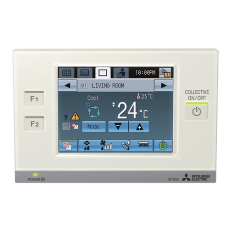
Mitsubishi Electric AT-50B User manual

Mitsubishi Electric
Mitsubishi Electric QE82LG User manual

Mitsubishi Electric
Mitsubishi Electric Central Controller G-50A User manual

Mitsubishi Electric
Mitsubishi Electric FX3U-J1939 User manual

Mitsubishi Electric
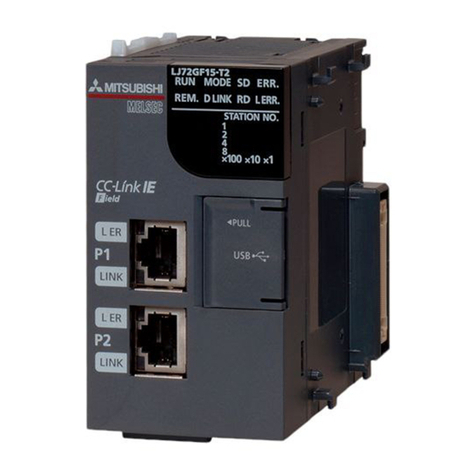
Mitsubishi Electric MELSEC-Q-MR-JE-C User manual
Mitsubishi Electric
Mitsubishi Electric MELSEC L series User manual

Mitsubishi Electric
Mitsubishi Electric TC-24A Manual
Mitsubishi Electric
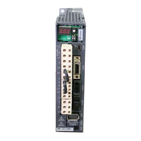
Mitsubishi Electric Melservo MR-J3-10B User manual
Mitsubishi Electric
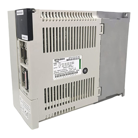
Mitsubishi Electric MELDAS MDS-B-SVJ2 Series User manual
Mitsubishi Electric
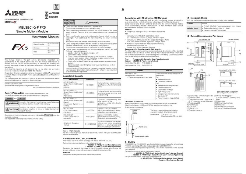
Mitsubishi Electric MELSEC iQ-F FX5 User manual
Mitsubishi Electric
Mitsubishi Electric MR-J5D-G User manual
Mitsubishi Electric
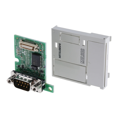
Mitsubishi Electric FX3U-232-BD User manual

Mitsubishi Electric
Mitsubishi Electric FX2N-32ASI-M User manual

Mitsubishi Electric
Mitsubishi Electric MELSEC iQ-F FX5 User manual
Mitsubishi Electric
Mitsubishi Electric Melsec iQ-R60AD8-G User manual
Mitsubishi Electric
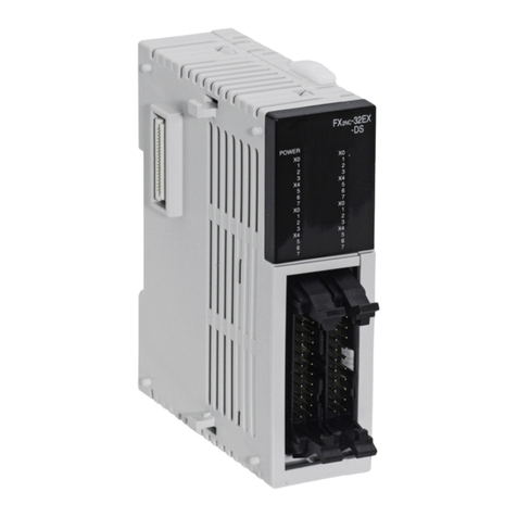
Mitsubishi Electric FX2NC-16EX-DS User manual

Mitsubishi Electric
Mitsubishi Electric R32MTCPU Owner's manual

Mitsubishi Electric
Mitsubishi Electric MELSEC Q Series User manual

Mitsubishi Electric
Mitsubishi Electric MELSEC iQ-F Series User manual
Mitsubishi Electric
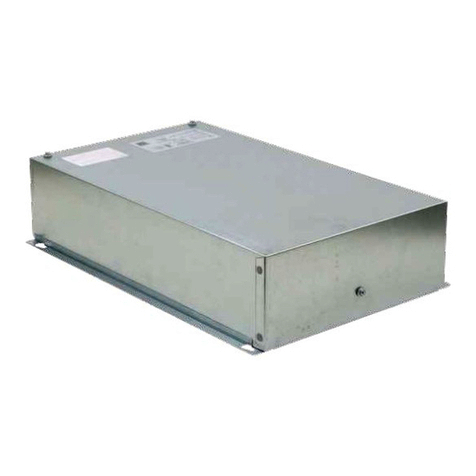
Mitsubishi Electric CITY MULTI PAC-AH001-1 User manual
Popular Controllers manuals by other brands

Digiplex
Digiplex DGP-848 Programming guide

YASKAWA
YASKAWA SGM series user manual

Sinope
Sinope Calypso RM3500ZB installation guide

Isimet
Isimet DLA Series Style 2 Installation, Operations, Start-up and Maintenance Instructions

LSIS
LSIS sv-ip5a user manual

Airflow
Airflow Uno hab Installation and operating instructions

