SMAR if303 Manual


web: www.smar.com/contactus.asp
www.smar.com
Specifications and information are subject to change without notice.
Up-to-date address information is available on our website.
smar

Introduction
III
INTRODUCTION
The IF303 is a converter mainly intended to interface analog transmitters to a Profibus PA network.
The IF303 receives up to three current signal typically 4-20 mA or 0-20 mA, and makes them
available to Profibus PA system. The digital technology used in the IF303 enables an easy interface
between the field and the control room and it has several interesting features that reduce
considerably the installation, operation and maintenance costs.
The IF303 is part of SMAR's complete 303 line of Profibus PA devices.
Profibus PA, is not only a replacement for 4-20 mA or intelligent/smart transmitter protocols, it
contains much more.
The digital technology used in the IF303 enables the choice of several types of transfer functions, an
easy interface between the field and the control room and several interesting features that
considerably reduce the installation, operation and maintenance costs.
Some of the advantages of bi-directional digital communications are known from existing smart
transmitter protocols: Higher accuracy, multi-variable access, remote configuration and diagnostics,
and multi-dropping of several devices on a single pair of wires.
The system controls variable sampling, algorithm execution and communication so as to optimize
the usage of the network, not loosing time. Thus, high closed loop performance is achieved.
Using Profibus technology, with its capability to interconnect several devices, very large control
schemes can be constructed. In order too be user friendly the function block concept was introduced
The IF303, like the rest of the 303 family, has some Function Blocks built in, like Analog Input and
Totalizer Blocks.
The need for implementation of Fieldbus in small as well as large systems was considered when
developing the entire 303 line of Profibus-PA devices. They have common features and can be
configured locally using a magnetic tool, eliminating the need for a configuration tool or console in
many basic applications.
Get the best result of the IF303 by carefully reading these instructions.
This product is protected by US patent number 5,706,007.

IF303 - Operation and Maintenance Instruction Manual
VI
WARNING
This Manual is compatible with version 1.XX, where 1 denotes software version and XX software release.
The indication 1.XX means that this manual is compatible with any release of software version 1.
Waiver of responsibility
The contents of this manual abides by the hardware and software used on the current equipment
version. Eventually there may occur divergencies between this manual and the equipment. The
information from this document are periodically reviewed and the necessary or identified corrections
will be included in the following editions. Suggestions for their improvement are welcome.
Warning
For more objectivity and clarity, this manual does not contain all the detailed information on the
product and, in addition, it does not cover every possible mounting, operation or maintenance
cases.
Before installing and utilizing the equipment, check if the model of the acquired equipment complies
with the technical requirements for the application. This checking is the user’s responsibility.
If the user needs more information, or on the event of specific problems not specified or treated in
this manual, the information should be sought from Smar. Furthermore, the user recognizes that the
contents of this manual by no means modify past or present agreements, confirmation or judicial
relationship, in whole or in part.
All of Smar’s obligation result from the purchasing agreement signed between the parties, which
includes the complete and sole valid warranty term. Contractual clauses related to the warranty are
not limited nor extended by virtue of the technical information contained in this manual.
Only qualified personnel are allowed to participate in the activities of mounting, electrical connection,
startup and maintenance of the equipment. Qualified personnel are understood to be the persons
familiar with the mounting, electrical connection, startup and operation of the equipment or othe
r
similar apparatus that are technically fit for their work. Smar provides specific training to instruct and
qualify such professionals. However, each country must comply with the local safety procedures,
legal provisions and regulations for the mounting and operation of electrical installations, as well as
with the laws and regulations on classified areas, such as intrinsic safety, explosion proof, increased
safety and instrumented safety systems, among others.
The user is responsible for the incorrect or inadequate handling of equipments run with pneumatic
or hydraulic pressure or, still, subject to corrosive, aggressive or combustible products, since thei
r
utilization may cause severe bodily harm and/or material damages.
The field equipment referred to in this manual, when acquired for classified or hazardous areas, has
its certification void when having its parts replaced or interchanged without functional and approval
tests by Smar or any of Smar authorized dealers, which are the competent companies for certifying
that the equipment in its entirety meets the applicable standards and regulations. The same is true
when converting the equipment of a communication protocol to another. In this case, it is necessary
sending the equipment to Smar or any of its authorized dealer. Moreover, the certificates are
different and the user is responsible for their correct use.
Always respect the instructions provided in the Manual. Smar is not responsible for any losses
and/or damages resulting from the inadequate use of its equipments. It is the user’s responsibility to
know and apply the safety practices in his country.

Table of Contents
V
TABLE OF CONTENTS
SECTION 1 - INSTALLATION..................................................................................................................... 1.1
GENERAL..................................................................................................................................................................................... 1.1
MOUNTING .................................................................................................................................................................................. 1.1
ELECTRIC WIRING...................................................................................................................................................................... 1.1
TOPOLOGY AND NETWORK CONFIGURATION....................................................................................................................... 1.3
INTRINSIC SAFETY BARRIER.................................................................................................................................................... 1.4
JUMPER CONFIGURATION........................................................................................................................................................ 1.5
POWER SUPPLY ......................................................................................................................................................................... 1.5
INPUT WIRING............................................................................................................................................................................. 1.5
SECTION 2 - OPERATION...........................................................................................................................2.1
FUNCTIONAL DESCRIPTION – ELECTRONICS.........................................................................................................................2.1
SECTION 3 - CONFIGURATION................................................................................................................. 3.1
TRANSDUCER BLOCK................................................................................................................................................................ 3.1
HOW TO CONFIGURE A TRANSDUCER BLOCK....................................................................................................................... 3.1
TERMINAL NUMBER ................................................................................................................................................................... 3.1
FUNCTIONAL DIAGRAM OF THE CURRENT TO PROFIBUS PA TRANSDUCER BLOCK....................................................... 3.2
CURRENT TO PROFIBUS PA TRANSDUCER BLOCK GENERAL PARAMETER DESCRIPTION............................................ 3.3
TRANSDUCER BLOCK PARAMETER ATTRIBUTES.................................................................................................................. 3.4
IF303 - CYCLIC CONFIGURATION.............................................................................................................................................. 3.5
HOW TO CONFIGURE THE ANALOG INPUT BLOCK................................................................................................................ 3.9
HOW TO CONFIGURE THE TOTALIZER BLOCK..................................................................................................................... 3.11
CURRENT TRIM......................................................................................................................................................................... 3.13
VIA LOCAL ADJUSTMENT ........................................................................................................................................................ 3.14
TRANSDUCER DISPLAY – CONFIGURATION......................................................................................................................... 3.15
DISPLAY TRANSDUCER BLOCK.............................................................................................................................................. 3.16
DEFINITION OF PARAMETERS AND VALUES ........................................................................................................................ 3.16
PROGRAMMING USING LOCAL ADJUSTMENT...................................................................................................................... 3.19
QUICK GUIDE – LOCAL ADJUSTMENT TREE......................................................................................................................... 3.21
J1 JUMPER CONNECTIONS..................................................................................................................................................... 3.22
W1 JUMPER CONNECTIONS ................................................................................................................................................... 3.22
SECTION 4 - MAINTENANCE PROCEDURES........................................................................................... 4.1
GENERAL..................................................................................................................................................................................... 4.1
TROUBLESHOOTING.................................................................................................................................................................. 4.1
DISASSEMBLY PROCEDURE..................................................................................................................................................... 4.2
REASSEMBLY PROCEDURE...................................................................................................................................................... 4.2
BOARDS INTERCHANGEABILITY .............................................................................................................................................. 4.3
EXPLODED VIEW ........................................................................................................................................................................ 4.3
ACCESSORIES............................................................................................................................................................................ 4.3
SPARE PARTS LIST .................................................................................................................................................................... 4.4
SECTION 5 - TECHNICAL CHARACTERISTICS ....................................................................................... 5.1
ORDERING CODE ....................................................................................................................................................................... 5.2
APPENDIX A – SRF – SERVICE REQUEST FORM...................................................................................A.1
RETURNING MATERIALS ...........................................................................................................................................................A.2
APPENDIX B – SMAR WARRANTY CERTIFICATE ..................................................................................B.1

IF303 - Operation and Maintenance Instruction Manual
VI

Installation Flowchart
VII
Installation Flowchart
Was the converter
configured on the bench
to match the application?
Configure the engineering unit.
Configure the terminal(s)
and input scale(s) .
(Section 3 - Calibration)
Configure the LCD reading.
(Section 3 - Configuration)
Simulate the value(s) in the 4 a
20 mA input and verify the
signal(s) in Fieldbus.
Start
No
Yes
Is the indication correct?
See section 4 - Maintenance
OK
Install the converter on the field
following the instructions below.
Check the area classification
and its practices.
Install the (mechanically
and electrically) according to the
application after checking the best
position for the LCD
(Section 4 - Maintenance).
converter
Install the preferably
on wether-protected areas.
converter
Power-up the properly.
IF303 needs a external power supply
for supply the equipment .
converter
4 - 20 mA
No
Yes

IF303 - Operation and Maintenance Instruction Manual
VIII

Section 1
1.1
INSTALLATION
General
The overall accuracy of measurement and control depends on several variables. Although the
converter has an outstanding performance, proper installation is essential, in order to maximize its
performance.
Among all factors, which may affect converter accuracy, environmental conditions are the most
difficult to control. There are, however, ways of reducing the effects of temperature, humidity and
vibration.
Locating the converter in areas protected from extreme environmental changes can improve the
converter performance.
In warm environments, the converter should be installed to avoid as much as possible, direct
exposure to the sun. Installation close to lines and vessels subjected to high temperatures should
also be avoided.
Use of sunshades or heat shields to protect the converter from external heat sources should be
considered, if necessary.
Humidity is fatal to electronic circuits. In areas subjected to high relative humidity, the O-rings for the
electronics cover must be correctly placed. Removal of the electronics cover in the field should be
reduced to the minimum necessary, since each time it is removed the circuits are exposed to the
humidity. The electronic circuit is protected by a humidity proof coating, but frequent exposures to
humidity may affect the protection provided. It is also important to keep the covers tightened in
place. Every time they are removed, the threads are exposed to corrosion, since painting cannot
protect these parts. Code-approved sealing methods on conduit entering the converter should be
employed.
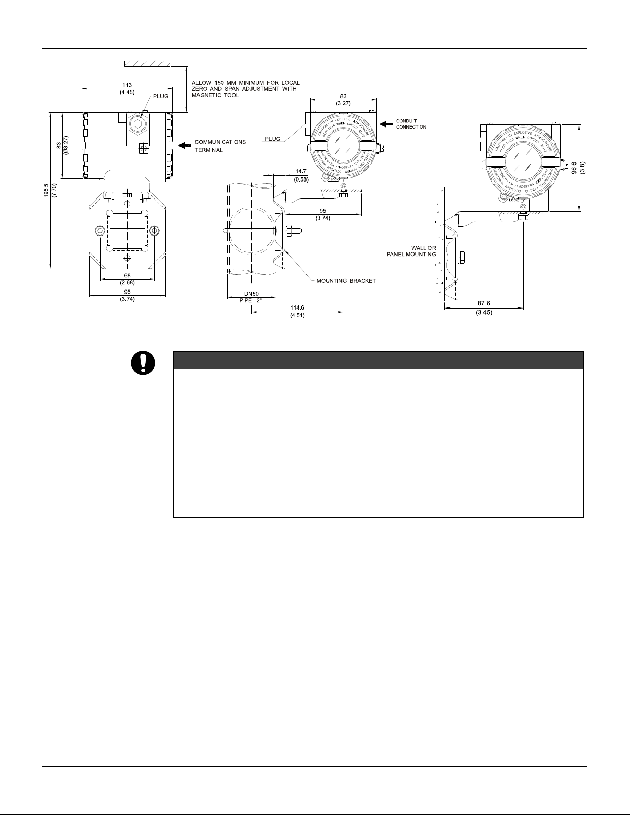
Mounting
Using the bracket, the mounting may be done in several positions, as shown on Figure 1.3 -
Dimensional Drawing and Mounting Positions.
For better visibility, the digital indicator may be rotated in steps of 90° (See Section 4 - Maintenance
Procedures).
Electric Wiring
Access the wiring block by removing the Electrical Connection Cover. This cover can be locked
closed by the cover locking screw (See Figure 1.1 - Cover Locking) To release the cover, rotate the
locking screw clockwise.
Cable access to wiring connections is obtained by one of the two conduit outlets. Conduit threads
should be sealed by means of code-approved sealing methods. The unused outlet connection
should be plugged accordingly.
The wiring block has screws, on which fork or ring type terminals can be fastened, see Figure 1.2 -
Terminal Block.

IF303 - Operation and Maintenance Instruction Manual
1.2
COVER
LOCKING
SCREW
Figure 1.1 - Cover Locking
For convenience there are three ground terminals: one inside the cover and two externals, located
close to the conduit entries.
GROUND
TERMINAL
PROFIBUS PA
A
ND POWER SUPPLY
TERMINALS
COMUNICATION
TERMINALS
INPUT
TERMINALS (3) INPUT
GROUND
TERMINAL
Figure 1.2 - Terminal Block
The IF303 uses the 31.25 kbit/s voltage mode option for the physical signaling. All other devices on
the same bus must use the same signaling.
Various types of Fieldbus devices may be connected on the same bus.
The IF303 is powered via the bus. The limit for such devices is according to the DP/PA coupler
limitations for one bus (one segment) for non-intrinsically safe requirement.
In hazardous area, the number of devices may be limited by intrinsically safe restrictions, according
to the DP/PA coupler and barriers limitations.
The IF303 is protected against reverse polarity, and can withstand ±35 VDC without damage, but it
will not operate when in reverse polarity.
NOTE
Please refer to the General Installation, Operation and Maintenance Procedures Manual for more details.
Installation
1.3
Figure 1.3 - Dimensional Drawing and Mounting Positions
WARNING
HAZARDOUS AREAS
In hazardous areas with explosion proof requirements, the covers must be tightened with at least 8 turns. In
order to avoid the penetration moisture or corrosive gases, tighten the O’ring until feeling the O'ring touching
the housing. Then, tighten more 1/3 turn (120°) to guarantee the sealing. Lock the covers using the locking
screw.
In hazardous zones with intrinsically safe or non-incentive requirements, the circuit entity parameters and
applicable installation procedures must be observed.
Cable access to wiring connections is obtained by the two conduit outlets. Conduit threads should be sealed
by means of code-approved sealing methods. The unused outlet connection should be plugged and sealed
accordingly.
Should other certifications be necessary, refer to the certification or specific standard for installation
limitations.
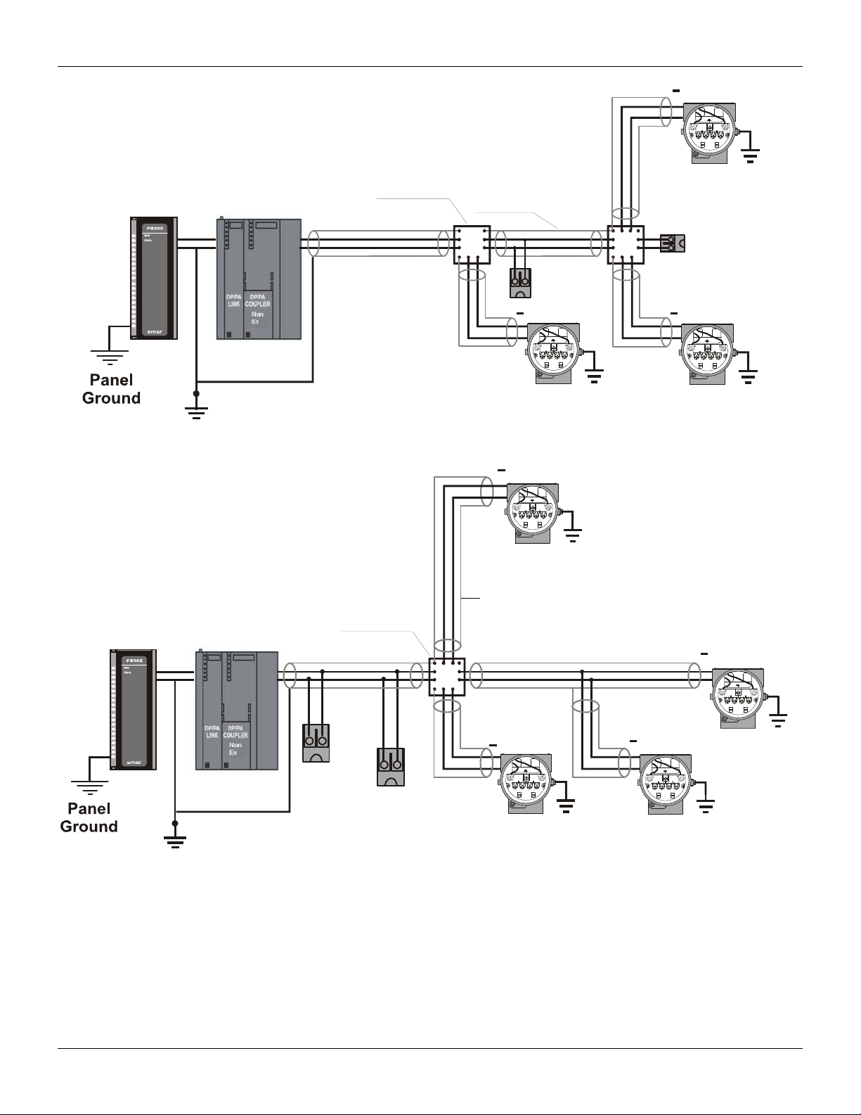
Topology and Network Configuration
Bus topology (See Figure 1.4 - Bus Topology) and tree topology (See Figure 1.5 - Tree Topology)
are supported. Both types have a trunk cable with two terminations. The devices are connected to
the trunk via spurs. The spurs may be integrated in the device giving zero spur length. A spur may
connect more than one device, depending on the length. Active couplers may be used to extend
spur length.
Active repeaters may be used to extend the trunk length.
The total cable length, including spurs, between any two devices in the Fieldbus should not exceed
1900m.
The connection of couplers should be kept less than 15 per 250m. In folowing figures DP/PA link
depends on the application needs.
IF303 - Operation and Maintenance Instruction Manual
1.4
Spur
Terminato
r
Spur
Spur
Shield
Junction
Box
++
+
Analog
Ground
+
-+
-
Figure 1.4 - Bus Topology
Analog
G
r
ou
n
d
+
-+
-
Coupler
++
+
+
Terminator
Enabled
Junction
Box
Terminator
Figure 1.5 - Tree Topology
Intrinsic Safety Barrier
When the Fieldbus is in an area requiring intrinsic safety, a barrier must be inserted on the trunk
between the power supply and the DP/PA coupler, when it is Non-Ex type.
Use of DF47 is recommended.

Installation
1.5
Jumper Configuration
In order to work properly, the jumpers J1 and W1 located in the IF303 main board must be correctly
configured (See Table 1.1 - Description of the Jumpers).
J1 This jumper enables the simulation mode parameter in the AI block.
W1 This jumper enables the local adjustment programming tree.
Table 1.1 - Description of the Jumpers
Power Supply
The IF303 receives power from the bus via the signal wiring. The power supply may come from a
separate unit or from another device such as a controller or DCS.
The voltage should be between 9 to 32 Vdc for non-intrinsic safe applications.
A special requirement applies to the power supply used in an intrinsically safe bus and depends on
the type of barrier used.
Use of PS302 is recommended as power supply.
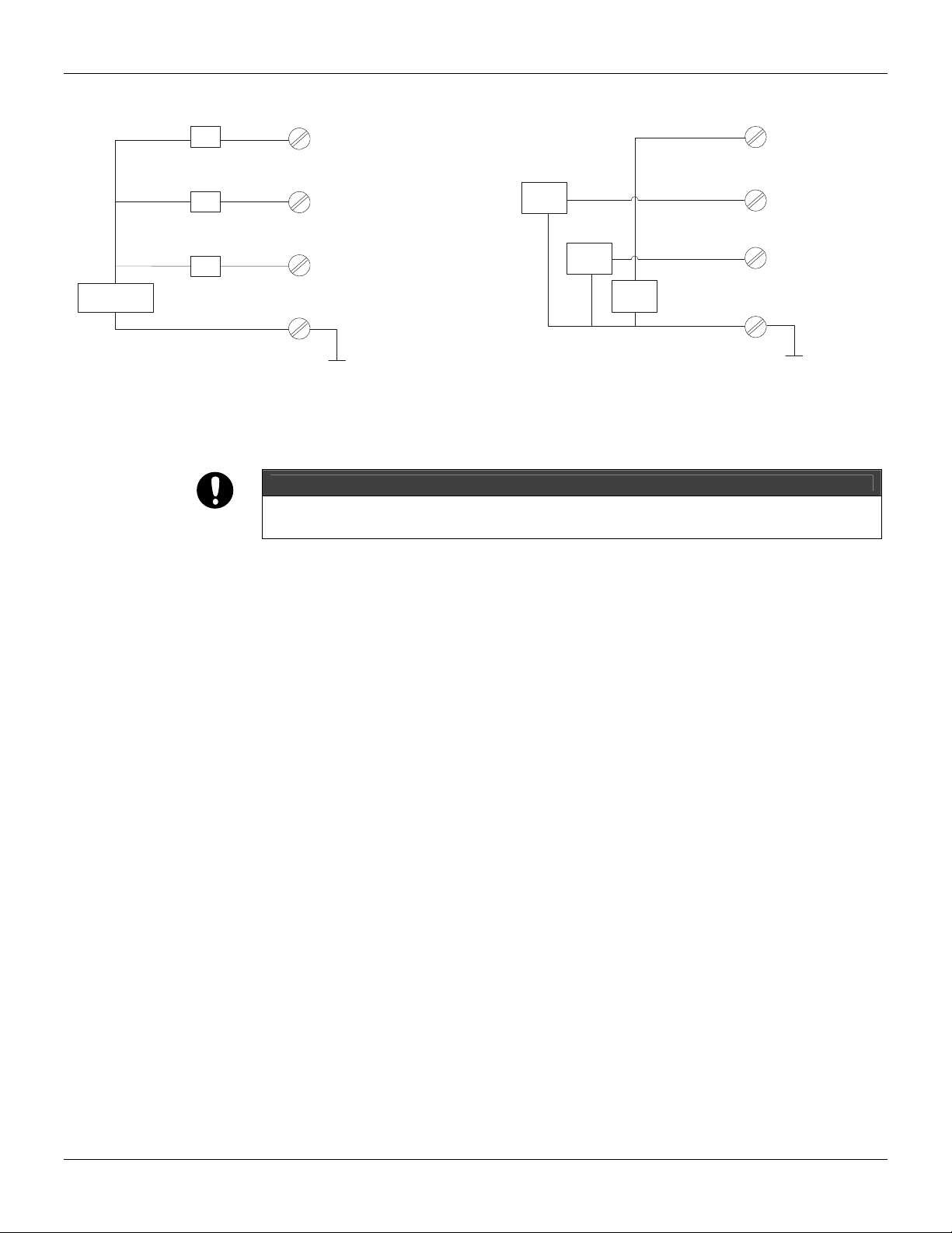
Input Wiring
The IF303 accepts up to three current inputs in the range 0-20 mA or 4-20 mA. The three inputs
have a common ground and they are protected from reverse polarity signal. The inputs should be
connected as per Figure 1.6 - Input Wiring.
PROFIBUS PA
1
2
3
4
4 to 20mA
POWER
SUPPLY
TRANSMITTER 1
IF303
TRANSMITTER 2
TRANSMITTER 3
Figure 1.6 - Input Wiring
IF303 - Operation and Maintenance Instruction Manual
1.6
Note that IF303 can operate with 0-20 mA or 4-20mA transmitters (See Figure 1.7 - Connection).
CHANNEL1
1
2
+
33
4
CHANNEL 2
4-20mA
CHANNEL 3
COMMON
1
2
4
CO
NNE
C
TI
O
N
+
Power
Supply
-
TR
TR
-
+
-
+
TR
-
+
TR = Transmitter
-
-
+
-
0-20mA
0-20mA
0-20mA
+
4-wire 0-20mA Transmitters or
0-20mA Current Generator
CHANNEL1
CHANNEL 2
CHANNEL 3
COMMON
Figure 1.7 - Connection
Avoid routing input wiring close to power cables or switching equipment.
WARNING
Apply in the inputs of the conversor only current levels. Don't apply tension levels, because the
shunt resistors are of 100R 1W and tension above 10 Vdc it can damage them.

Section 2
2.1
OPERATION
The IF303 accepts signals from mA generators such as most conventional transmitters. It is
therefore ideal for interfacing existing equipment to a Fieldbus system.
Functional Description – Electronics
See Figure 2.2 - IF303 Block Diagram. The function of each block is described below.
MUX Multiplexer
The MUX multiplexes the input terminals to ensure that all three channels reach the A/D converter.
A/D Converter
The A/D converts the input signals to a digital format for the CPU.
Signal Isolator
Its function is to isolate the data signal between the input and the CPU.
(CPU) Central Processing Unit, RAM and FLASH
The CPU is the intelligent portion of the converter, being responsible for the management and
operation of block execution, self-diagnostics and communication. The program is stored in Flash
memory. For temporary storage of data there is a RAM. The data in the RAM is lost if the power is
switched off, however the device also has a nonvolatile EEPROM where data that must be retained
are stored. Examples of such data are: calibration, configuration and identification data.
Communication Controller
It monitors line activity, modulates and demodulates the signal from network line.
Power Supply
Takes power of the loop-line to power the converter circuitry.
Power Isolation
Just like the signals from the input section, the power to the input section must be isolated.
Display Controller
Receives data from the CPU and drives the Liquid Crystal Display.
Local Adjustment
They are two switches that are magnetically activated. They can be activated by the magnetic tool
without mechanical or electrical contact.

IF303 – Operation and Maintenance Instruction Manual
2.2
Figure 2.1 - LCD Indicator
MAIN CIRCUIT BOARD INPUT CIRCUIT BOARD
SUPPLY
POWER
SUPPLY
SIGNAL
SHAPING
DISPLAY BOARD
FIRMWARE
DOWNLOAD
INTERFACE
LOCAL ADJUST
CPU
EEPROM
FLASH
RAM
MODEM
POWER
ISOLATION
DISPLAY
CONTROLLER
S
I
G
N
A
L
I
S
O
L
A
T
I
O
N
(*) Resistor Shunt
(3 x 100R)
Figure 2.2 - IF303 Block Diagram
* WARNING
Apply in the inputs of the conversor only current levels. Don’t apply tension levels, because the shunt
resistors are of 100R 1W and tension higher than 10 Vdc can damage them.

Section 3
3.1
CONFIGURATION
One of the many advantages of Fieldbus is that device configuration is independent of the
configurator. The IF303 may be configured by a third party terminal or operator console.
The IF303 contains three input transducer blocks, one physical block, one display transducer block ,
three analog input and three totalizer function blocks.
Function Blocks are not covered in this manual. For explanation and details of function blocks, see
the “Function Blocks Manual”.
Offline Configuration
1. First run “Download to PG/PC” option to assure valid values.
2. Run after the Menu Device option to configure the required parameters using the related menus.
NOTE
It is not advisable to use the “Download to Device” option. This function can misconfigure the equipment.
Transducer Block
Transducer block insulates function block from the specific I/O hardware, such as sensors and
actuators. Transducer block controls access to I/O through manufacturer specific implementation.
This permits the transducer block to execute as frequently as necessary to obtain good data from
sensors without burdening the function blocks that use the data. It also insulates the function blocks
from the manufacturer specific characteristics of certain hardware.
By accessing the hardware, the transducer block can get data from I/O or passing control data to it.
The connection between Transducer block and Input/Output Function blocks is called channel.
Normally, transducer blocks perform functions, such as linearization, characterization, temperature
compensation, control and exchange data to/from hardware.
How to Configure a Transducer Block
The transducer block has an algorithm, a set of contained parameters and a channel connecting it to
a function block. The algorithm describes the behavior of the transducer as a data transfer function
between the I/O hardware and other function block. The set of contained parameters, it means, you
are not able to link them to other blocks, defines the user interface to the transducer block. They can
be divided into Standard and Manufacturer Specific.
The standard parameters will be present for such class of device, as pressure, temperature,
actuator, etc., whatever is the manufacturer. Oppositely, the manufacturers specific ones are
defined only by its manufacturer. As common manufacturer specific parameters, we have calibration
settings, material information, linearization curve, etc.
When you perform a standard routine as a calibration, you are conducted step by step by a method.
The method is generally defined as guide line to help the user to make common tasks. The
Configuration Tool identifies each method associated to the parameters and enables the interface
to it.
Terminal Number
The terminal number, which references a physical input, which is sent internally from the specified
transducer output to function block.
It starts at channel one (1) for transducer number one until channel three (3) for transducer number
three.
The channel number of the AI block and TOT block is related to the transducer’s terminal number.
Channel number 1, 2, 3 corresponds bi-univocally to the terminal block with the same number.
Therefore, all the user has to do is to select combinations: (1.1), (2.2), (3,3) for (CHANNEL,
BLOCK).

IF303 – Operation and Maintenance Instruction Manual
3.2
Functional Diagram of the Current To Profibus PA Transducer Block
Current
Acquisition
3 Channels
mA mA
Limit
Checking User Current
Characterization mA
Scale In 100%
10%
100% %
Factory Trim
User Trim
Secondary value 1
AI Channel Secondary
Value 2
% %
SQR
Root
Scale Out 100%
Scale Out 10%10%
100% Primary Value
AL: Channel
TOT: Channel
Lin Type
Low Flow Cut Off
Low Lin Sqrt Point
Primary Value Unit
Scale In 10%
Figure 3.1 - Functional Diagram of the Current To Profibus PA Transducer Block

Configuration
3.3
Current To Profibus PA Transducer Block General Parameter Description
Parameter Description
BACKUP_RESTORE
This parameter allows to save and to restore data according to factory and user calibration
procedures. It has the following options:
1, "Factory Cal Restore",
2, "Last Cal Restore",
3, "Default Data Restore",
4, "Shut-Down Data Restore",
11, "Factory Cal Backup",
12, "Last Cal Backup",
14, "Shut-Down Data Backup",
0, "None".
CAL_MIN_SPAN This parameter contains the minimum calibration span value allowed. This minimum span
information is necessary to ensure that when calibration is done, the two calibrated points (high
and low) are not too close together. Unit derives from SENSOR_UNIT.
CAL_POINT_HI This parameter contains the highest calibrated value. For calibration of the high limit point you
give the high measurement value (pressure) to the sensor and transfer this point as HIGH to the
transmitter. Unit derives from SENSOR_UNIT.
CAL_POINT_LO This parameter contains the lowest calibrated value. For calibration of the low limit point you give
the low measurement value (pressure) to the sensor and transfer this point as LOW to the
transmitter. Unit derives from SENSOR_UNIT.
LIN_TYPE Linearization Type:
0– No Linearization
10 – Square Root
LOW_FLOW_CUT_OFF
This is the point in percent of flow till that the output of the flow function is set to zero. It
is used for suppressing low flow values.
FLOW_LIN_SQRT_POINT
This is the point of the flow function where the curve changes from linear to square root
function.
The input has to be done in percent of flow.
MAINT_DATE The date of last maintenance.
EEPROM_FLAG This parameter is used to indicate EEPROM saving process.
FACTORY_GAIN_REFERENCE Factory calibration reference value.
MAIN_BOARD_SN This is the main board serial number.
MAX_SENSOR_VALUE Holds the maximum process SENSOR_VALUE. A write access to this parameter resets to the
momentous value. The unit is defined in SENSOR_UNIT.
MIN_SENSOR_VALUE Holds the minimum process SENSOR_VALUE. A write access to this parameter resets to the
momentous value. The unit is defined in SENSOR_UNIT.
ORDERING_CODE Indicates information about the sensor and control from production factory.
PRIMARY_VALUE This parameter contains the measured value and status available to the Function Block. The unit
of PRIMARY_VALUE is the PRIMARY_VALUE_UNIT.
PRIMARY_VALUE_TYPE This parameter contains the application of the device.
> 128: manufacturer specific
PRIMARY_VALUE_UNIT This parameter contains the engineering units index code for the primary value. In this case the
unit code is mA (1211).
SECONDARY_VALUE_1 This parameter contains the current value and status available to the Function Block.
SECONDARY_VALUE_1_UNIT This parameter contains the current units of the SECONDARY_VALUE_1. In this case the unit
code is mA (1211).
SECONDARY_VALUE_2 This parameter contains the measured value after input scaling and status available to the
Function Block. The related unit is the SECONDARY_VALUE_UNIT_2. In this case the unit code
is % (1342).
SECONDARY_VALUE_2_UNIT This parameter contains the units of the SECONDARY_VALUE_2 defined by the manufacturer. In
the this case the unit code mA (1211).

IF303 – Operation and Maintenance Instruction Manual
3.4
Parameter Description
SCALE_IN This is the input conversion of the current into PRIMARY_VALUE using the high and low scale.
The related unit is the PRIMARY_VALUE_UNIT.
SCALE_OUT This is the output conversion value using the high and low scale. The related unit is the
PRIMARY_VALUE_UNIT.
SENSOR_HI_LIM This parameter contains the sensor upper limit value. Unit derives from SENSOR_UNIT.
SENSOR_LO_LIM This parameter contains the sensor lower limit value. Unit derives from SENSOR_UNIT.
SENSOR_UNIT This parameter contains the engineering units index code for the calibration values. In this case
the unit code is mA (1211).
SENSOR_SN The serial number of sensor.
SENSOR_VALUE This parameter contains the raw sensor value. The uncalibrated measurement value from the
sensor. Unit derives from SENSOR_UNIT.
TERMINAL_NUMBER The terminal number, which references a channel value, which is sent via internal, manufacturer-
specific from AI function block to the specified transducer. It starts at one (1) for transducer
number one until three (3) for transducer number three.
TRIMMED_VALUE This parameter contains the sensor value after the trim processing. Unit derives from
SENSOR_UNIT.
XD_ERROR
Indicates the condition of calibration process according to:
{16, "Default value set"},
{22, "Applied process out of range"},
{26, "Invalid configuration for request"},
{27, "Excess correction"},
{28, "Calibration failed"}
Table 3.1 - Parameter Description
Transducer Block Parameter Attributes
Relative
Index Parameter Mnemonic Object
Type Data Type Store Size Access
Parameter
usage/
Type of
transport
Default
value
Down-
load
Order
Mandatory /
Optional
(Class) View
... Standard Parameter 1
Additional Parameter for Transducer Block
8 SENSOR_VALUE Simple Float D 4 r C/a 0 - M (B)
9 SENSOR_HI_LIM Simple Float N 4 r C/a 0 - M (B)
10 SENSOR_LO_LIM Simple Float N 4 r C/a 0 - M (B)
11 CAL_POINT_HI Simple Float N 4 r,w C/a 20.0 - M (B)
12 CAL_POINT_LO Simple Float N 4 r,w C/a 4.0 - M (B)
13 CAL_MIN_SPAN Simple Float N 4 r C/a 0 - M (B)
14 MAINT_DATE Simple Octet String S 16 w,w C/a O(B)
15 SENSOR_UNIT Simple Unsigned 16 N 2 r,w C/a 1211 - M (B)
16 SENSOR_SN Simple Unsigned 32 N 4 r,w C/a - M (B)
17 TRIMMED_VALUE Record DS-33 D 5 r C/a 0.0 - M (B)
18 PRIMARY_VALUE Record DS-33 D 5 r C/a 0.0 - M (B) 1
19 PRIMARY_VALUE_UN
IT Simple Unsigned 16 N 2 r,w C/a - - M (B)
20 PRIMARY_VALUE_TY
PE Simple Unsigned 16 N 2 r,w C/a 255 - M (B)
21 SECONDARY_VALUE Record DS-33 D 5 r C/a 0.0 - O (B)
Other manuals for if303
1
Table of contents
Other SMAR Media Converter manuals


