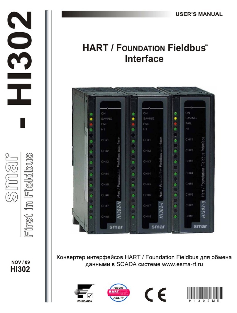
SMAR FI302 Manual

FI302
OPERATION & MAINTENANCE
INSTRUCTIONS MANUAL
FI 302ME

web: www.smar.com/contactus.asp
www.smar.com
Specifications and information are subject to change without notice.
Up-to-date address information is available on our website.
smar

Kpvtqfwevkqp"
KKK"
INTRODUCTION
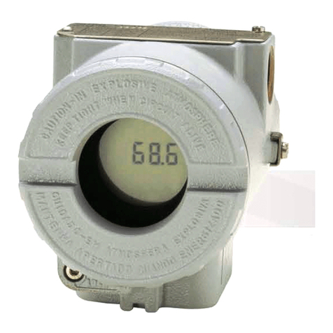
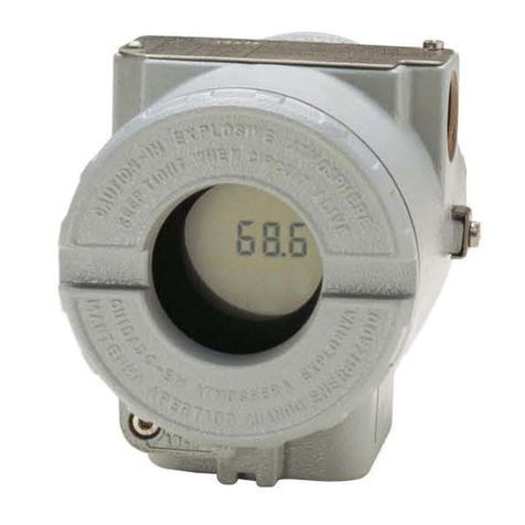
The FI302 is part of Smar´s first generation of FOUNDATION™ fieldbus field equipment. It is a
converter intended to connect Foundation Fieldbus systems with actuators and positioners for 4 -20
mA control valves. The FI302 produces a 4 -20 mA output proportional to the input received by the
Fieldbus network. Its digital technology enables an easy interface between the field and the control
room, while offering several types of transference functions and interesting features that reduce
installation, operation and maintenance costs.
Foundation Fieldbus is a digital communication system that enables distributing control functions for
field equipment and advantageously replaces conventional technology.
Other protocols only disclose maintenance data, as they were not devised for control data. The main
Fieldbus goal was to overcome this situation. Closed loop control with a 4 -20 mA performance
requires high speed, which means higher power consumption – a feature that is not compatible with
intrinsic safety. This fact led to the use of a moderately high communication speed and to devise a
system with a minimum communication capability. Using scheduling synchronization, the system
controls variable sampling, algorithm execution and communication. The network treatment is
optimized and high circuit loop performance is achieved.
Using Foundation Fieldbus Technology with its capability to interconnect several devices, very large
projects can be constructed. The function block concept allows the user to easily construct the
programming and overview complex control strategies (Smar CD600 users are familiar with this
concept, since it was implemented a few years ago). Another advantage is flexibility, as the control
strategy may be edited without having to rewire or change any hardware.
The FI302 and the Smar FOUNDATION™ fieldbus family have function blocks that avoid the need for
separate equipment and facilitate implementing the control strategy. Among these function blocks,
the following may be enhanced: PID controller, Input Selector, Arithmetic, Signal Characterizer and
Integrator. These built-in blocks improve control, reduce communication, dead-time and costs.
Any FOUNDATION™ fieldbus equipment with Master Backup rapidity may work as a network master
and be locally configured using a magnetic screwdriver in several situations. This tool eliminates the
need for a configurator in many basic applications.
Read carefully these instructions to get the best result from the FI302.

HK524"/"Qrgtcvkqp"cpf"Ockpvgpcpeg"Kpuvtwevkqp"Ocpwcn"
KX"
NOTE
This manual is compatible with version 3.XX. The 3 indicates the software version and the XX indicates the
release. The 3.XX sign means that this manual is compatible with any release of software version-3
Waiver of responsibility
The contents of this manual abides by the hardware and software used on the current equipmen
t
version. Eventually there may occur divergencies between this manual and the equipment. The
information from this document are periodically reviewed and the necessary or identified corrections
will be included in the following editions. Suggestions for their improvement are welcome.
Warning
For more objectivity and clarity, this manual does not contain all the detailed information on the
product and, in addition, it does not cover every possible mounting, operation or maintenance
cases.
Before installing and utilizing the equipment, check if the model of the acquired equipment complies
with the technical requirements for the application. This checking is the user’s responsibility.
If the user needs more information, or on the event of specific problems not specified or treated in
this manual, the information should be sought from Smar. Furthermore, the user recognizes that the
contents of this manual by no means modify past or present agreements, confirmation or judicial
relationship, in whole or in part.
All of Smar’s obligation result from the purchasing agreement signed between the parties, which
includes the complete and sole valid warranty term. Contractual clauses related to the warranty are
not limited nor extended by virtue of the technical information contained in this manual.
Only qualified personnel are allowed to participate in the activities of mounting, electrical connection,
startup and maintenance of the equipment. Qualified personnel are understood to be the persons
familiar with the mounting, electrical connection, startup and operation of the equipment or othe
r
similar apparatus that are technically fit for their work. Smar provides specific training to instruct and
qualify such professionals. However, each country must comply with the local safety procedures,
legal provisions and regulations for the mounting and operation of electrical installations, as well as
with the laws and regulations on classified areas, such as intrinsic safety, explosion proof, increased
safety and instrumented safety systems, among others.
The user is responsible for the incorrect or inadequate handling of equipments run with pneumati
c
or hydraulic pressure or, still, subject to corrosive, aggressive or combustible products, since thei
r
utilization may cause severe bodily harm and/or material damages.
The field equipment referred to in this manual, when acquired for classified or hazardous areas, has
its certification void when having its parts replaced or interchanged without functional and approval
tests by Smar or any of Smar authorized dealers, which are the competent companies for certifying
that the equipment in its entirety meets the applicable standards and regulations. The same is true
when converting the equipment of a communication protocol to another. In this case, it is necessar
y
sending the equipment to Smar or any of its authorized dealer. Moreover, the certificates are
different and the user is responsible for their correct use.
Always respect the instructions provided in the Manual. Smar is not responsible for any losses
and/or damages resulting from the inadequate use of its equipments. It is the user’s responsibility to
know and apply the safety practices in his country.

Vcdng"qh"Eqpvgpvu"
"
X"
TABLE OF CONTENTS
UGEVKQP"3"/"KPUVCNNCVKQP"0000000000000000000000000000000000000000000000000000000000000000000000000000000000000000000000000000000000000000000000000000000000000000000000000000000000"303"
GENERAL...................................................................................................................................................................................... 1.1
MOUNTING ................................................................................................................................................................................... 1.1
ELECTRIC CONNECTION ............................................................................................................................................................ 1.2
OUTPUT CONNECTION ........................................................................................................................................................... 1.2
CONNECTING THE FI302 TO THE FOUNDATION™ FIELDBUS................................................................................................ 1.3
PREPARING THE FI302 BEFORE CONNECTING IT TO NETWORK ......................................................................................... 1.3
POWER CONSUMPTION ............................................................................................................................................................. 1.5
TERMINATOR ............................................................................................................................................................................... 1.5
CABLING ....................................................................................................................................................................................... 1.5
TOTAL CABLE LENGTH ............................................................................................................................................................... 1.6
CABLE SHIELDING....................................................................................................................................................................... 1.7
GROUNDING ............................................................................................................................................................................ 1.7
COMMISSIONING......................................................................................................................................................................... 1.7
COMMISSIONING STAGES ..................................................................................................................................................... 1.7
USE OF NON-PRECONFIGURED TO DEVICES ..................................................................................................................... 1.7
USE OF PRECONFIGURED EQUIPMENTS ............................................................................................................................ 1.8
LINKING DEVICE ...................................................................................................................................................................... 1.8
ERROR MONITORING AND DETECTION WITH LIVE LIST .................................................................................................... 1.8
INSTALLATION IN HAZARDOUS AREAS .................................................................................................................................... 1.8
EXPLOSION/FLAME PROOF ....................................................................................................................................................... 1.9
INTRINSICALLY SAFE.................................................................................................................................................................. 1.9
UGEVKQP"4"/"HWPEVKQPCN"FGUETKRVKQP"000000000000000000000000000000000000000000000000000000000000000000000000000000000000000000000000000000000000000000000000000000000000"403"
FUNCTIONAL DESCRIPTION ...................................................................................................................................................... 2.1
UGEVKQP"5"/"QRGTCVKQP"000000000000000000000000000000000000000000000000000000000000000000000000000000000000000000000000000000000000000000000000000000000000000000000000000000000000000"503"
LIQUID CRYSTAL DISPLAY ........................................................................................................................................................ 3.1
MONITORING ............................................................................................................................................................................... 3.1
UGEVKQP"6"/"EQPHKIWTCVKQP"000000000000000000000000000000000000000000000000000000000000000000000000000000000000000000000000000000000000000000000000000000000000000000000000000000"603"
TRANSDUCER BLOCK................................................................................................................................................................. 4.1
HOW TO CONFIGURE A TRANSDUCER BLOCK..................................................................................................................4.1
DISPLAY BLOCK .......................................................................................................................................................................... 4.2
HOW TO CONFIGURE A DISPLAY BLOCK ...........................................................................................................................4.2
UGEVKQP"7"/"ECNKDTCVKQP"000000000000000000000000000000000000000000000000000000000000000000000000000000000000000000000000000000000000000000000000000000000000000000000000000000000000"703"
UGEVKQP"8"/"OCKPVGPCPEG"0000000000000000000000000000000000000000000000000000000000000000000000000000000000000000000000000000000000000000000000000000000000000000000000000000000000"803"
DIAGNOSTIC BLOCK – DIAG...................................................................................................................................................... 6.1
TROUBLESHOOTING .................................................................................................................................................................. 6.1
PHYSICAL INSPECTION......................................................................................................................................................... 6.1
PARAMETERS USED FOR TROUBLESHOOTING ................................................................................................................ 6.1
DISASSEMBLE PROCEDURE..................................................................................................................................................... 6.3
EXPLODED VIEW ........................................................................................................................................................................ 6.3
ELECTRONIC CIRCUIT ............................................................................................................................................................... 6.4
ASSEMBLY PROCEDURE........................................................................................................................................................... 6.4
INTERCHANGEABILITY............................................................................................................................................................... 6.4
SPARES ....................................................................................................................................................................................... 6.5
SPARE PART LIST....................................................................................................................................................................... 6.5
UGEVKQP"9"/"CFXCPEGF"EQPHKIWTCVKQP"000000000000000000000000000000000000000000000000000000000000000000000000000000000000000000000000000000000000000000000000000000000"903"
CHARACTERIZATION CURVE..................................................................................................................................................... 7.1
DEFINITION OF PARAMETERS AND VALUES ........................................................................................................................... 7.3
UGEVKQP":"/"NQECN"CFLWUVOGPV"00000000000000000000000000000000000000000000000000000000000000000000000000000000000000000000000000000000000000000000000000000000000000000000000":03"
JUMPER CONFIGURATION ......................................................................................................................................................... 8.1
JUMPER J1 CONNECTION .......................................................................................................................................................... 8.1
JUMPER W1 CONNECTION......................................................................................................................................................... 8.2
UGEVKQP";"/"VGEJPKECN"EJCTCEVGTKUVKEU"00000000000000000000000000000000000000000000000000000000000000000000000000000000000000000000000000000000000000000000000000000";03"
ORDERING CODE ........................................................................................................................................................................ 9.2
Other manuals for FI302
1
Table of contents
Other SMAR Media Converter manuals
Popular Media Converter manuals by other brands

H&B
H&B TX-100 Installation and instruction manual

Bolin Technology
Bolin Technology D Series user manual

IFM Electronic
IFM Electronic Efector 400 RN30 Series Device manual

GRASS VALLEY
GRASS VALLEY KUDOSPRO ULC2000 user manual

Linear Technology
Linear Technology DC1523A Demo Manual

Lika
Lika ROTAPULS I28 Series quick start guide

Weidmuller
Weidmuller IE-MC-VL Series Hardware installation guide

Optical Systems Design
Optical Systems Design OSD2139 Series Operator's manual

Tema Telecomunicazioni
Tema Telecomunicazioni AD615/S product manual

KTI Networks
KTI Networks KGC-352 Series installation guide

Gira
Gira 0588 Series operating instructions

Lika
Lika SFA-5000-FD user guide
