Siko IV58M Operation manual

IH58M, IV58M Datum 03.08.2007 Art.Nr. 81826 Änd. Stand 202/07 1
IH58M
IV58M
A vor B
Abb. 1: Montagehinweise
DEUTSCH
1. Gewährleistungshinweise
Lesen Sie vor der Montage und der Inbetriebnahme
dieses Dokument sorgfältig durch. Beachten Sie zu
Ihrer eigenen Sicherheit und der Betriebssicherheit
alle Warnungen und Hinweise.
Ihr Produkt hat unser Werk in geprüftem und be-
triebsbereitem Zustand verlassen. Für den Betrieb
gelten die angegeben Spezifikationen und die
Angaben auf dem Typenschild als Bedingung.
Garantieansprüche gelten nur für Produkte der
Firma SIKO GmbH. Bei dem Einsatz in Verbindung
mit Fremdprodukten besteht für das Gesamtsystem
kein Garantieanspruch.
Reparaturen dürfen nur im Werk vorgenommen
werden. Für weitere Fragen steht Ihnen die Firma
SIKO GmbH gerne zur Verfügung.
Fremdmagnete fernhalten.
•
•
•
•
•
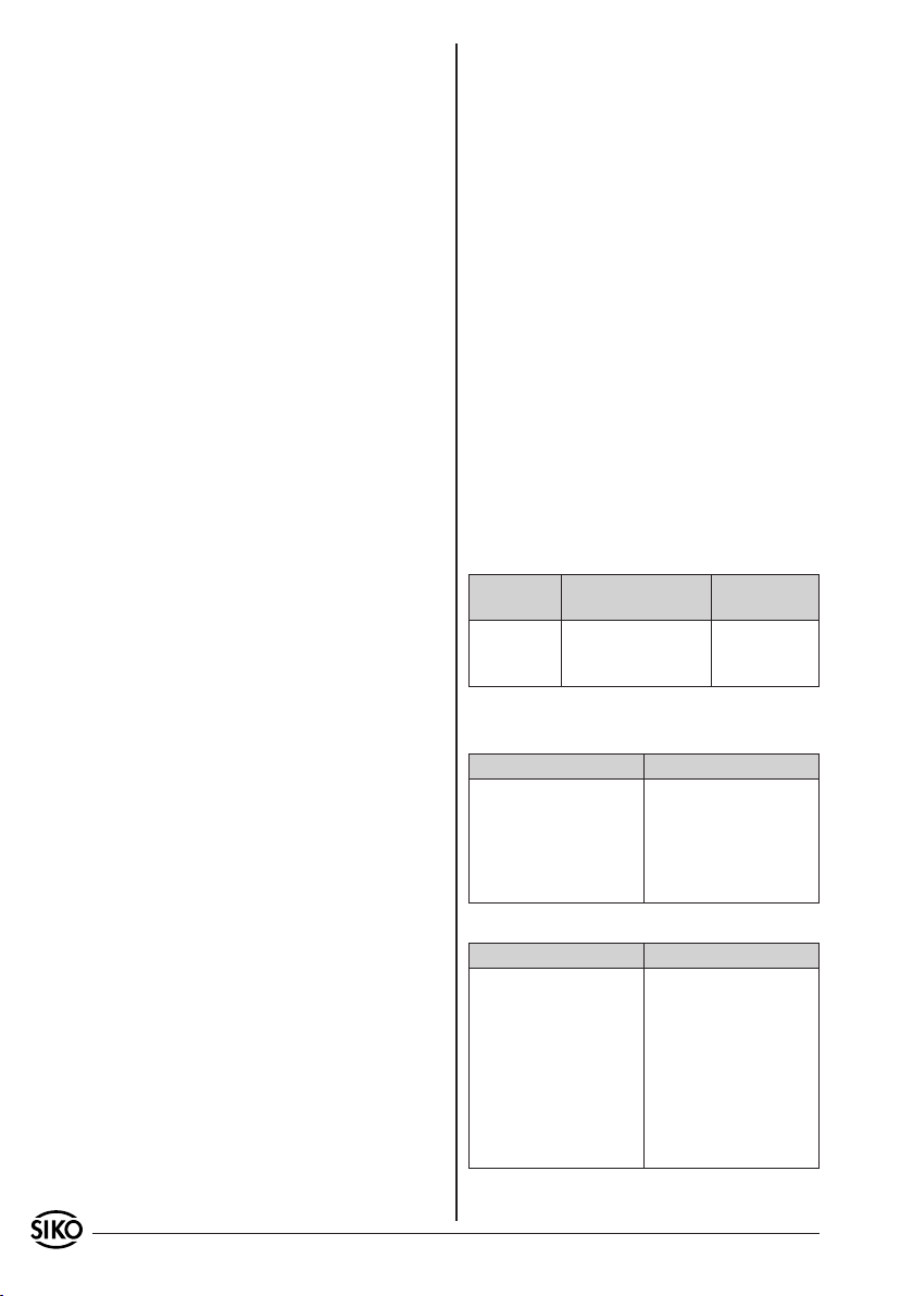
z.B. IH58M-0023
Varianten-Nr.
Geräte-Typ
3. Mechanische Montage
Die Montage darf nur gemäß der angegebenen IP-
Schutzart vorgenommen werden. Das Gerät muss
ggfs. zusätzlich gegen schädliche Umwelteinflüs-
se, wie z.B. Spritzwasser, Staub, Schläge, Tempe-
ratur geschützt werden.
Achtung! Radialdichtringe sind Verschleißteile!
Die Schutzart ist deshalb abhängig von Lebens-
dauer und Zustand der Dichtringe.
Montagehinweise
Gehen Sie sorgfältig mit dem Geber um. Es handelt
sich um ein Präzisionsmessgerät. Folgende Punkte
führen unverzüglich zum Verfall der Garantie:
Zerlegen oder Öffnen des Gebers (soweit dies
nicht in dieser Benutzerinformation beschrieben
wird).
Unsachgemäße Kupplung der Geberwelle z.B. mit
steifen Kupplungen, die zu große Kräfte auf die
Lagerung der Geberwelle erzeugen.
Schläge auf den Geber oder die Welle, da dadurch
interne Elemente beschädigt werden können.
Mechanische Bearbeitung der Welle, des Flansches
oder Gehäuses (Bohren, Fräsen, usw.). Hierdurch
kann es zu schweren Beschädigungen der inneren
Teile des Gebers kommen.
Unzulässige axiale oder radiale Belastung der
Welle.
Unsachgemäße Befestigung des Gebers.
Was Sie nicht tun sollten
•
•
•
•
•
•
Benutzerinformation
IH58M, IV58M
Inkrementalgeber
2. Identifikation
Das Typenschild zeigt den Gerätetyp mit Varianten-
nummer. Die Lieferpapiere ordnen jeder Varianten-
nummer eine detaillierte Bestellbezeichnung zu.
2 IH58M, IV58M Datum 03.08.2007 Art.Nr. 81826 Änd. Stand 202/07
Anbau des Gebers
Die Befestigung erfolgt mittels Schrauben oder
Drehmomentabstützung und Klemmung der Welle.
Montieren Sie den Geber möglichst verspannungs-
frei und mit Drehmomentstütze.
Kräfte dürfen nicht durch das Gehäuse übertragen
werden. Sie dürfen ausschließlich an der Welle
des Geräts wirken.
Beachten Sie die maximalen axialen und radialen
Wellenbelastungen.
Achten Sie auf geringen Wellen- und Winkelversatz.
Bei nicht korrekter axialer oder winkliger Stellung
zwischen Welle und Flansch entstehen Spannungen
im Lager, die über erhöhte Erwärmung bis zur
Zerstörung der Lager führen können.
4. Elektrischer Anschluss
Steckverbindungen dürfen nie unter Spannung
gesteckt oder abgezogen werden!
Alle Verdrahtungsarbeiten dürfen nur spannungs-
los erfolgen.
Litzen sind mit geeigneten Aderendhülsen zu
versehen.
Vor dem Einschalten sind alle Leitungsanschlüsse
und Steckverbindungen zu überprüfen.
Die Betriebsspannung des Gebers muss gemein-
sam mit der der Folgeelektronik (z.B. Steuerung)
eingeschaltet werden.
Nicht benutzte Signalleitungen sind über einen
Widerstand (z.B. R = 10 kOhm) gegen Masse zu
schalten.
Hinweise zur Störsicherheit
Alle Anschlüsse sind gegen äußere Störeinflüsse
geschützt. Der Einsatzort ist aber so zu wählen,
dass induktive oder kapazitive Störungen nicht
auf das Gerät oder deren Anschlussleitungen
einwirken können! Störungen können z.B. von
Schaltnetzteilen, Motoren, getakteten Reglern
oder Schützen verursacht werden. Durch geeigne-
te Kabelführung und Verdrahtung können Störein-
flüsse vermindert werden.
Erforderliche Maßnahmen
Nur geschirmtes Kabel verwenden. Den Kabel-
schirm beidseitig auflegen. Litzenquerschnitt der
Leitungen min. 0,14mm², max. 0,5mm².
Die Verdrahtung von Abschirmung und Masse (GND)
muss sternförmig und großflächig erfolgen.
Das System muss in möglichst großem Abstand von
Leitungen eingebaut werden, die mit Störungen
belastet sind; ggfs. sind zusätzliche Maßnahmen
•
•
•
•
•
•
•
•
•
•
•
•
•
wie Schirmbleche oder metallisierte Gehäuse
vorzusehen. Leitungsführungen parallel zu Ener-
gieleitungen vermeiden.
Schützspulen müssen mit Funkenlöschgliedern
beschaltet sein.
Spannungsversorgung
Die Spannungswerte sind abhängig von der Ge-
räteausführung und sind den Lieferpapieren oder
dem Typenschild zu entnehmen.
10 ... 30 VDC
5 VDC±5%
Allgemeine Hinweise
Bitte beachten Sie:
Löten Sie nur mit dem Feinlötkolben (15 ... max.
50 Watt Leistung).
Verwenden Sie nur Lötdraht Pb Sn 60 mit Kolo-
phonium als Flußmittel (DIN 8516)
Zur einfachen Montage muss der Kabelmantel
gegenüber dem Schirm verschiebbar sein.
Verwenden Sie möglichst nur die in der folgenden
Tabelle empfohlenen geschirmten Kabel.
Ausgangs-
schaltung
Kabelempfehlung Außendurch-
messer
PP Li12YC11Y 5x0,25mm² ca. 5,4 mm
OP, LD24 Li12YC11Y 8x0,14mm² ca. 5,4 mm
LD5 LiY12C11Y 10x0,14mm² ca. 6,5 mm
4.1 Anschlussart E1V (offenes Kabelende)
Ausgangsschaltung PP
Farbe Belegung
grau GND
gelb Kanal A
weiß Kanal B
grün Kanal 0/I
braun +UB
Ausgangsschaltung OP, LD24
Farbe Belegung
grau GND
gelb Kanal A
weiß Kanal B
grün Kanal 0
braun +UB
rosa Kanal /A
blau Kanal /B
rot Kanal I
•
•
•
•
•
IH58M, IV58M Datum 03.08.2007 Art.Nr. 81826 Änd. Stand 202/07 3
Ansichtseite =
Steckseite
Ansichtseite =
Steckseite
Ansichtseite =
Steckseite
Schirm
Schirm
Ausgangsschaltung LD5
Farbe Belegung
gelb Kanal A
grün Kanal 0
rosa Kanal /A
weiß Kanal B
blau Kanal /B
violett +SUB (Senseleitung)
schwarz SGND (Senseleitung)
rot Kanal /0
grau GND
braun +UB
Bei Ausgangsschaltung "LD" ist eine Kabellänge
von max. 100m möglich, wenn der Geber mit ei-
nem Netzteil versorgt wird, welches dafür sorgt,
dass am Geber 5V anliegen. Das Netzgerät muss
für den Anschluss der "Sense"-Leitungen (+SUB
und SGND) vorbereitet sein.
4.2 Anschlussart E2
Ausgangsschaltung PP 12-pol. Stiftkontakt
Pin Belegung
1 - - -
2 - - -
3 Kanal 0/I
4 - - -
5 Kanal A
6 - - -
7 - - -
8 Kanal B
9 - - -
10 GND
11 - - -
12 +UB
Ausgangsschaltung OP, LD24 12-pol. Stiftkontakt
Pin Belegung
1 Kanal /B
2 - - -
3 Kanal 0
4 Kanal I
5 Kanal A
6 Kanal /A
7 - - -
8 Kanal B
9 - - -
10 GND
11 - - -
12 +UB
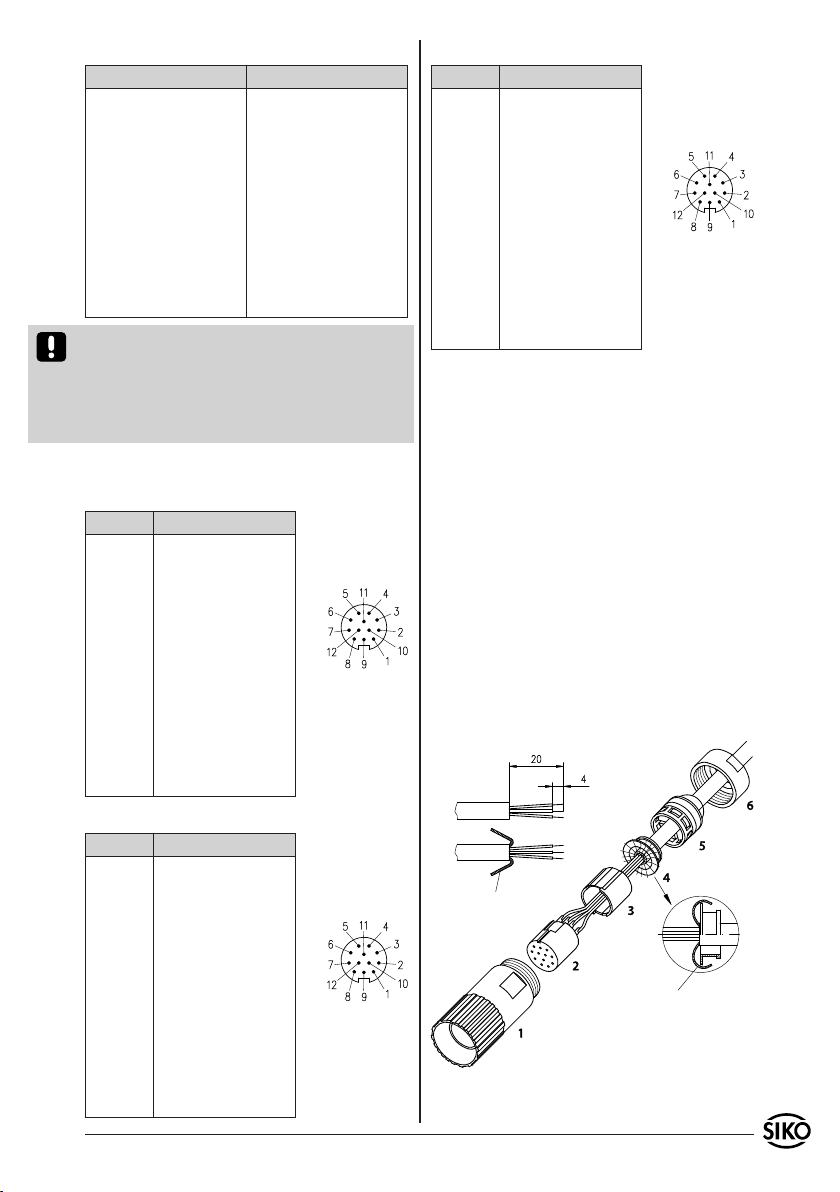
Ausgangsschaltung LD5 12-pol. Stiftkontakt
Pin Belegung
1 Kanal /B
2 +SUB (Senseleitung)
3 Kanal 0
4 Kanal I
5 Kanal A
6 Kanal /A
7 - - -
8 Kanal B
9 - - -
10 GND
11 SGND (Senseleitung)
12 +UB
Gegenstecker und Kabelverlängerungen sind bei
Firma SIKO als Zubehör erhältlich:
Montageanweisung für Gegenstecker (Zubehör)
Pos. 4 ... 6 über Kabelmantel schieben.
Kabel abisolieren.
Schirm umlegen.
Litzen an Pos. 2 löten (entspr. Anschluss-
plan).
Abstandhülse Pos. 3 aufweiten und über Litzen
stülpen, zusammendrücken und auf Pos. 2 ste-
cken. Schlitz und Nut (Pos. 2 und 3) müssen
deckungsgleich sein.
Pos. 2+3+4 in Pos. 1 einschieben, überstehender
Schirm abschneiden.
Pos. 5 in Pos. 1 einschieben.
Pos. 6 aufschrauben.
1.
2.
3.
4.
5.
6.
7.
8.

4 IH58M, IV58M Datum 03.08.2007 Art.Nr. 81826 Änd. Stand 202/07
Abb. 2: Impulsbild
Abb. 3: Timing, Signale Inkrementalgeber
5. Inbetriebnahme
Bitte beachten Sie die Hinweise auf ordnungsge-
mäßen mechanischen und elektrischen Anschluss.
Nur dann sind die Voraussetzungen für eine pro-
blemlose Inbetriebnahme und einwandfreien Be-
trieb gegeben.
Prüfen Sie vor der Inbetriebnahme insbesondere
nochmals auf:
korrekte Polung der Betriebsspannung.
korrekten Anschluss des Kabels und der Signale.
festen Sitz des Gebers und der Hohlwelle.
Die Betriebsspannung des Gebers muss gemein-
sam mit der der Folgeelektronik (z.B. Steuerung)
eingeschaltet werden, um Latchup-Effekte an den
Ausgängen des Gebers zu vermeiden.
--> Nehmen Sie den Geber elektrisch in Betrieb.
6. Ausgangsschaltungen
PP
•
•
•
OP
LD24
LD5
6.1 Ausgangssignale / Impulsbild

IH58M, IV58M Datum 03.08.2007 Art.Nr. 81826 Änd. Stand 202/07 5
IH58M
IV58M
A before B
Fig. 1: Mounting instructions
ENGLISH
1. Warranty information
In order to carry out installation correctly, we
strongly recommend this document is read very
carefully. This will ensure your own safety and
the operating reliability of the device.
Your device has been quality controlled, tested
and is ready for use. Please observe all warnings
and information which are marked either directly
on the device or specified in this document.
Warranty can only be claimed for components
supplied by SIKO GmbH. If the system is used
together with other products, there is no warranty
for the complete system.
Repairs should be carried out only at our works.
If any information is missing or unclear, please
contact the SIKO sales staff.
Keep away foreign magnets.
•
•
•
•
•
delivery documentation.
e.g. IH58M-0023
version number
type of unit
3. Installation
For mounting, the degree of protection specified
must be observed. If necessary, protect the unit
against environmental influences such as sprayed
water, dust, knocks, extreme temperatures.
Important information! Radial shaft sealings are
subject to wear! Protection class therefore de-
pends on life and condition of sealings.
Mounting instructions
Please handle the encoder carefully as it is a high-
precision device.
Especially do not:
disassemble or open the encoder (unless stipulated
in this brochure).
link encoder's shaft with rigid couplings as this
would expose the encoder's shaft bearing to
high forces.
knock on casing or shaft; the encoder's inner
components could be damaged.
machine (bore, mill ...) flange or shaft. This could
lead to severe damage inside the encoder.
exceed the values for the maximum axial and
radial shaft load.
mount the encoder incorrectly.
Otherwise manufacturer's warranty will be invalidated!
NEVER ...
•
•
•
•
•
•
User Information
IH58M, IV58M
Incremental encoder
2. Identification
Please check the particular type of unit and type
number from the identification plate. Type number
and the corresponding version are indicated in the

6 IH58M, IV58M Datum 03.08.2007 Art.Nr. 81826 Änd. Stand 202/07
Mounting of the encoder
Fixation either by screws or via torque pin and shaft
clamping. Ensure that the encoder is mounted
without strain and use torque pin.
Forces must not be transmitted via the housing,
but only via the shaft.
Do not exceed the values for the maximum axial
and radial shaft load.
Ensure accurate shaft alignment. If shaft and
flange are not correctly aligned, strain on the
bearings will result, which will overheat and be
irreparably damaged.
4. Electrical connection
Switch power off before any plug is inserted or
removed!
Any wiring must only be carried out without
power.
Provide stranded wires with ferrules.
Check all lines and connections before switching
on the equipment.
The encoder's and follower electronic's (eg.
control unit) operating supply must be switched
on simultaneously.
Encoders with parallel output: Unconnected signal
lines must be provided with a resistor (eg.: R =
10 kOhm) and connected to earth.
Interference and distortion
All connections are protected against the effects
of interference. The location should be selected
to ensure that no capacitive or inductive in-
terferences can affect the encoder or the con-
nection lines! Suitable wiring layout and choice
of cable can minimise the effects of interference
(eg. interference caused by SMPS, motors, cyclic
controls and contactors).
Necessary measures
Only screened cable should be used. Wire cross sec-
tion is to be at least 0,14mm², max. 0,5mm².
Wiring to the screen and ground (0V) must be
secured to a good point.
The system should be positioned well away from
cables with interference; if necessary a protective
screen or metal housing must be provided. The
running of wiring parallel to the mains supply
should be avoided.
Contactor coils must be linked with spark sup-
pression.
•
•
•
•
•
•
•
•
•
•
•
•
•
•
Power supply
Supply voltage depends on the unit type and is
indicated in the delivery documentation and on
the identification plate.
10 ... 30 V d.c.
5 V d.c.±5%
General information
The following points should be observed:
Use for soldering precision copper bit (perfor-
mance 15 ... 50 Watt max.).
Use only tin solder wire type Pb Sn 60 with
colophonium fluxing agent (DIN 8516).
Cable outer and screening must be able to slide
to allow easy mounting.
If possible, use only the sreened cables recom-
mended in the list below.
Output
circuit
Recommended
cable
Outside
diameter
PP Li12YC11Y 5x0,25mm² ca. 5,4 mm
OP, LD24 Li12YC11Y 8x0,14mm² ca. 5,4 mm
LD5 LiY12C11Y 10x0,14mm² ca. 6,5 mm
4.1 Connection type E1V (flying leads)
Output circuit PP
Color Designation
grey GND
yellow channel A
white channel B
green channel 0/I
brown +UB
Output circuit OP, LD24
Color Designation
grey GND
yellow channel A
white channel B
green channel 0
brown +UB
pink channel /A
blue channel /B
red channel I
Output circuit LD5
Color Designation
yellow channel A
green channel 0
pink channel /A
white channel B
•
•
•
•
IH58M, IV58M Datum 03.08.2007 Art.Nr. 81826 Änd. Stand 202/07 7
viewing side =
plug-in side
viewing side =
plug-in side
viewing side =
plug-in side
screening
screening
Color Designation
blue channel /B
violet +SUB (Sense line)
black SGND (Sense line)
red channel /0
grey GND
brown +UB
With output circuit 'LD' max. cable length is 100m,
provided that the encoder is combined with a po-
wer supply unit feeding the encoder with 5V. The
power supply unit must allow connection of the
"Sense" lines (+SUB and SGND).
4.2 Connection type E2
Output circuit PP 12 pole plug pin
Pin Designation
1 - - -
2 - - -
3 channel 0/I
4 - - -
5 channel A
6 - - -
7 - - -
8 channel B
9 - - -
10 GND
11 - - -
12 +UB
Output circuit OP, LD24 12 pole plug pin
Pin Designation
1 channel /B
2 - - -
3 channel 0
4 channel I
5 channel A
6 channel /A
7 - - -
8 channel B
9 - - -
10 GND
11 - - -
12 +UB
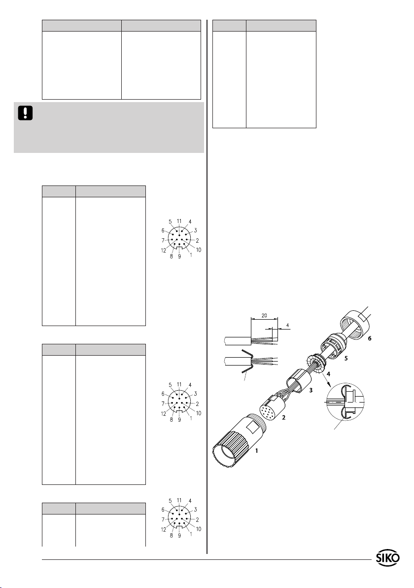
Output circuit LD5 12 pole plug pin
Pin Designation
1 channel /B
2 +SUB (Sense line)
3 channel 0
Pin Designation
4 channel I
5 channel A
6 channel /A
7 - - -
8 channel B
9 - - -
10 GND
11 SGND (Sense line)
12 +UB
Counter-plugs and cable extensions available as
accessories from SIKO:
Mounting instructions for counter-plug (accessory)
Slip parts 4 to 6 over outer cable.
Strip cable.
Turn down screening.
Solder stranded wires at part 2 (follow connec-
tion diagram).
Open spacer (part 3) and put it over ferrules,
squeeze and push it onto part 2. Slot and keyway
of parts 2 and 3 must align.
Slide parts 2+3+4 into part 1; cut prodruding
screening.
Slide part 1 into part 5.
Screw up part 6.
1.
2.
3.
4.
5.
6.
7.
8.
5. Commissioning
Please carefully read the information on the
encoder's mechanical and electrical connection.
This will ensure a trouble free commissioning and
operation.
Before operation, please check again:
that the supply voltage's polarity is correct.•

8 IH58M, IV58M Datum 03.08.2007 Art.Nr. 81826 Änd. Stand 202/07
Fig. 2: Wave form
Fig. 3: Timing, incremental encoder signals
SIKO GmbH
Werk / Factory:
Weihermattenweg 2
79256 Buchenbach-Unteribental
Postanschrift / Postal address:
Postfach 1106
79195 Kirchzarten
Telefon/Phone +49 7661 394-0
Telefax/Fax +49 7661 394-388
E-Mail info@siko.de
Internet www.siko.de
Service [email protected]e
correct connection of cable and signal lines
secure encoder fixation on the hollow shaft.
The encoder's and follower electronic's (eg. con-
trol unit) operating supply must be switched on
simultaneoulsy to avoid latch-up effects on the
encoder's outputs.
--> Now the encoder can be used.
6. Output circuits
PP
•
•
OP
LD24
LD5
6.1 Output signals / Wave form
This manual suits for next models
1
Table of contents
Languages:
Other Siko Media Converter manuals


