SMAR HI302 User manual

HART / Foundation Fieldbus
SCADA www.esma-rt.ru

web: www.smar.com/contactus.asp
www.smar.com
Specifications and information are subject to change without notice.
Up-to-date address information is available on our website.
smar

Introduction
III
INTRODUCTION
The HI302 is a device integrated to System302 which main function is to interface HART devices to
FOUNDATIONTM fieldbus systems, allowing the user to perform maintenance, calibration, sensor
status monitoring, device status, among other information. See below some HI302 features:
•Integral part of System302.
•Tight integration with different system manufactures due to the use of standard protocols such
as FOUNDATIONTM fieldbus and HART.
•8 HART master channels.
•Optional Analog Conversion (4-20 mA / FOUNDATIONTM fieldbus – HI302-I and FOUNDATIONTM
fieldbus / 4-20 mA – HI302-O).
•Totally integrated to AssetView.
•Uniform systems and tools, making it easy to operate and reducing maintenance costs.
•Non-multiplexed and independent HART channels.
•HART Configuration Commands located into the module, allowing HART messages to be sent
through bypass parameters.
•Suitable for Asset Management systems.
•Complete configuration of Smar devices enclosed in the HI302 module, thus no additional
configuration is required.
•Configuration for third party equipments can also be embedded in the Flash memory or added
through FOUNDATIONTM fieldbus blocks.
•Registered in Fieldbus FOUNDATION, it successfully has passed by rigorous interoperability tests.

HI302 - User’s Manual
IV

Table of Contents
V
TABLE OF CONTENTS
CHAPTER 1 - OVERVIEW...........................................................................................................................1.1
GENERAL CHARACTERISTICS ................................................................................................................................1.1
FUNCTION BLOCKS ..................................................................................................................................................1.2
HART COMMUNICATION BLOCKS...........................................................................................................................1.2
ANALOG BLOCKS......................................................................................................................................................1.3
TECHNICAL CHARACTERISTICS.............................................................................................................................1.4
CHAPTER 2 - INSTALLATION....................................................................................................................2.1
INSTALLATION OF THE HI302 MODULES...............................................................................................................2.1
MECHANICAL INSTALLATION..................................................................................................................................................2.1
ELECTRICAL CONNECTIONS..................................................................................................................................................2.1
HART DEVICE INSTALLATION..................................................................................................................................2.4
DEVICE TYPES ..........................................................................................................................................................2.4
LOW IMPEDANCE DEVICES ....................................................................................................................................................2.4
HIGH IMPEDANCE DEVICES....................................................................................................................................................2.4
HART INSTALLATION TOPOLOGY...........................................................................................................................2.4
SUPPLY VOLTAGE VS. TOTAL LOOP IMPEDANCE...............................................................................................................2.5
EXAMPLE WITH HI302-N (WITHOUT ANALOG CONVERSION) .............................................................................................2.5
HI302-I (4-20 MA TO FOUNDATION FIELDBUS CONVERSION).............................................................................................2.6
HI302-O (FOUNDATION FIELDBUS TO 4-20 MA CONVERSION)...........................................................................................2.7
MAXIMUM CABLE LENGTH.......................................................................................................................................2.7
OTHER DEVICES IN THE LOOP...............................................................................................................................2.7
PORTABLE CONFIGURATOR ..................................................................................................................................................2.7
INDICATORS AND CONVERTERS IN GENERAL.....................................................................................................................2.8
SWITCHING ON THE HI302.......................................................................................................................................2.8
UPDATING THE HI302 FIRMWARE ..........................................................................................................................2.8
CHAPTER 3 - BASIC CONFIGURATION ...................................................................................................3.1
INSTRUCTIONS ON HI302 CONFIGURATION.........................................................................................................3.1
CONFIGURING THE HCFG BLOCK..........................................................................................................................3.2
HART COMMUNICATION OPERATION PARAMETERS..........................................................................................................3.2
HART COMMUNICATION DIAGNOSTIC PARAMETERS.........................................................................................................3.3
CONFIGURING THE HIRT BLOCK............................................................................................................................3.3
CONFIGURING THE HVT BLOCK.............................................................................................................................3.7
HI302-I - CONFIGURING THE MAI OR AI BLOCKS..................................................................................................3.8
HI302-O – CONFIGURING THE MAO OR AO BLOCKS ...........................................................................................3.8
STARTING THE HI302 OPERATION.........................................................................................................................3.8
CALIBRATING THE HI302 ANALOG BOARDS .........................................................................................................3.8
HI302-I CALIBRATION (GLL1205).............................................................................................................................................3.9
HI302-O CALIBRATION (GLL1194)...........................................................................................................................................3.9
CHAPTER 4 - ADVANCED CONFIGURATION ..........................................................................................4.1
SPECIFIC HART COMMAND CONFIGURATION WITH HCD AND HWPC BLOCKS..............................................4.1
BASIC INSTRUCTIONS ON HART PROTOCOL.......................................................................................................4.1
TYPES OF HART COMMANDS..................................................................................................................................4.1
DESCRIBING THE HART COMMANDS.....................................................................................................................4.2
SETTING THE DEFINITION OF THE HART COMMANDS........................................................................................4.2
CONFIGURING THE HCD BLOCK.............................................................................................................................4.3
MAPPING THE HART VARIABLE AS FOUNDATION FIELDBUS PARAMETERS...................................................................4.4
HVT ALLOCATION MAP AND COMMAND DESCRIPTION......................................................................................4.4
REQUEST PARAMETERS .........................................................................................................................................4.4
RESPONSE PARAMETERS.......................................................................................................................................4.4
WHAT ABOUT THE RESPONSE CODE?..................................................................................................................4.5
COMMAND 0..............................................................................................................................................................................4.7
COMMAND 3..............................................................................................................................................................................4.8
COMMAND 13............................................................................................................................................................................4.9
COMMAND 18..........................................................................................................................................................................4.10

HI302 - User’s Manual
VI
WHAT ABOUT THE PARAMETER WRITING?........................................................................................................4.11
SETTING THE HWPC BLOCK CONFIGURATION..................................................................................................................4.11
CONFIGURATION OF THE HWPC FOR THE GIVEN EXAMPLE...........................................................................................4.11
CHAPTER 5 - OPERATION.........................................................................................................................5.1
INITIALIZATION..........................................................................................................................................................5.1
LEDS STATUS............................................................................................................................................................5.1
LED ON......................................................................................................................................................................................5.1
LED FAIL....................................................................................................................................................................................5.1
LED SAVING..............................................................................................................................................................................5.2
H1 LED.......................................................................................................................................................................................5.2
CH#1 TO CH#8 LEDS................................................................................................................................................................5.2
AUXILIARY PUSH BUTTONS.....................................................................................................................................5.2
UNDERSTANDING THE HART COMMUNICATION..................................................................................................5.3
BLK_EXEC_STATE PARAMETER ............................................................................................................................................5.3
BLK_ERROR AND DEVICE_STATUS PARAMETERS .............................................................................................................5.4
HIRT BLOCK OPERATION........................................................................................................................................................5.4
HART VARIABLE WRITING AND READING .............................................................................................................5.5
HART VARIABLES READING CYCLES ....................................................................................................................................5.5
WRITING ON PARAMETERS THAT MAP THE HART VARIABLES .........................................................................................5.5
OPERATING THE HVT BLOCK..................................................................................................................................5.7
SEQUENCE FOR HVT READING CYCLE.................................................................................................................................5.7
WRITING SEQUENCE IN HVT BLOCK PARAMETER..............................................................................................................5.8
HI302 VERSUS PORTABLE PROGRAMMERS (FIELD ALTERATIONS).................................................................5.9
STATIC REVISION (ST_REV) PARAMETER.............................................................................................................5.9
CONCLUSIONS ON THE STATIC REVISION:........................................................................................................................5.10
HART RESPONSE CODE CONVERSION TO STATUS FOUNDATION FIELDBUS..............................................5.10
BYPASS MODE ........................................................................................................................................................5.10
SEQUENCE FOR SENDING A HART MESSAGE THROUGH A BYPASS.............................................................................5.11
EXAMPLE..................................................................................................................................................................5.11
CHAPTER 6 - BASIC FUNCTIONING THEORY.........................................................................................6.1
THE HI302 BLOCK DIAGRAM....................................................................................................................................6.1
HARDWARE................................................................................................................................................................6.1
POWER SUPPLY, OPERATION VOLTAGE AND PROTECTION.............................................................................6.2
HOT SWAP ................................................................................................................................................................................6.2
REGULATORS...........................................................................................................................................................................6.2
PROTECTION............................................................................................................................................................................6.2
ELECTROSTATIC DISCHARGE (ESD).....................................................................................................................................6.3
SURGES, HIGH VOLTAGE AND GROUNDING........................................................................................................................6.3
PROCESSING CORE.................................................................................................................................................6.3
FIRMWARE PROGRAMMING ...................................................................................................................................................6.3
EPLD PROGRAMMING .............................................................................................................................................................6.4
MANUAL RESET KEY AND FACTORY INIT.............................................................................................................................6.4
HI302 MODULE RESETTING.....................................................................................................................................6.5
H1 FIELDBUS COMMUNICATION.............................................................................................................................6.5
HART COMMUNICATION...........................................................................................................................................6.5
4-20MA TO FOUNDATION FIELDBUS ANALOG CONVERSION (HI302-I)..............................................................6.5
FOUNDATION FIELDBUS TO 4-20MA ANALOG CONVERSION (HI302-O)............................................................6.6
CHAPTER 7 - AN EXAMPLE OF HI302 USAGE........................................................................................7.1
INSTALLATION...........................................................................................................................................................7.1
STEP BY STEP CONFIGURATION............................................................................................................................7.1
STEP BY STEP OPERATION.....................................................................................................................................7.3
CHAPTER 8 - TROUBLESHOOTING .........................................................................................................8.1
INSTALLATION...........................................................................................................................................................8.1
CONFIGURATION ......................................................................................................................................................8.1
OPERATION ...............................................................................................................................................................8.2
QUESTIONS AND ANSWERS....................................................................................................................................8.3

Table of Contents
VII
APPENDIX A - HCFG - HART CONFIGURATION & DIAGNOSTIC.......................................................... A.1
HIRT - HART INFORMATION & DYNAMIC DATA AND HUT – HART UNIVERSAL TRANSDUCER ......................A.3
HVT – HART VARIABLE TEMPLATE.......................................................................................................................A.12
HCD – HART COMMAND DEFINITION ...................................................................................................................A.14
HWPC – HART WRITE PARAMETER CONFIGURATION......................................................................................A.16
HBC - HART BYPASS COMMUNICATION..............................................................................................................A.17
APPENDIX - B - HART COMMAND CONFIGURATION IN FLASH MEMORY......................................... B.1
HIRT BLOCK...............................................................................................................................................................B.1
SENT HART READING COMMAND USED BY THE HIRT BLOCK...........................................................................B.1
IDENTIFICATION HART COMMANDS.......................................................................................................................B.1
HART WRITING AND EXECUTION COMMANDS USED BY THE HIRT BLOCK.....................................................B.1
HVT BLOCK ................................................................................................................................................................B.2
APPENDIX C - HVT'S ALLOCATION MAP ...............................................................................................C.1
HVT'S ALLOCATION MAP FOR FY301 .................................................................................................................... C.1
HVT'S ALLOCATION MAP FOR LD301 .................................................................................................................... C.6
HVT'S ALLOCATION MAP FOR TT301................................................................................................................... C.10
HVT'S ALLOCATION MAP FOR DT301.................................................................................................................. C.14
HVT'S ALLOCATION MAP FOR TP301 .................................................................................................................. C.17
HVT'S ALLOCATION MAP FOR LD291 .................................................................................................................. C.18
APPENDIX D - CODES FOR SMAR HART VARIABLES AND CONFIGURATION OF THE HIRT BLOCK
FOR THE ASSETVIEW............................................................................................................................... D.1
FY301 INTELLIGENT VALVE POSITIONER............................................................................................................. D.1
AVAILABLE VARIABLES ..........................................................................................................................................................D.1
CONFIGURATION OF THE HIRT BLOCK FOR ASSETVIEW..................................................................................................D.1
LD301 AND LD291 INTELLIGENT PRESSURE TRANSMITTER............................................................................. D.2
VARIABLES LIST OF THE HART COMMAND #33...................................................................................................................D.2
CONFIGURATION OF THE HIRT BLOCK FOR ASSETVIEW..................................................................................................D.2
TT301 INTELLIGENT TEMPERATURE TRANSMITTER.......................................................................................... D.2
VARIABLES LIST OF THE HART COMMAND #33...................................................................................................................D.2
CONFIGURATION OF THE HIRT BLOCK FOR ASSETVIEW..................................................................................................D.2
DT301 INTELLIGENT DENSITY TRANSMITTER..................................................................................................... D.3
VARIABLES LIST OF THE HART COMMAND #33...................................................................................................................D.3
CONFIGURATION OF THE HIRT BLOCK FOR ASSETVIEW..................................................................................................D.3
TP301 INTELLIGENT PRESSURE TRANSMITTER................................................................................................. D.3
VARIABLES LIST OF THE HART COMMAND #33...................................................................................................................D.3
CONFIGURATION OF THE HIRT BLOCK FOR ASSETVIEW..................................................................................................D.3
APPENDIX E – SRF – SERVICE REQUEST FORM.................................................................................. E.1
APPENDIX F - SMAR WARRANTY CERTIFICATE....................................................................................F.1

HI302 - User’s Manual
VIII

Chapter 1
OVERVIEW
This user’s manual contains instructions about how to install and configure the HI302. If the user
already knows how to install the FOUNDATIONTM fieldbus and HART devices and wants to work with
the HI302 immediately, please, go to the chapter 7.
This manual is compliant to firmware version 6.01 or later and DD 0601 and CF 060101 (or later).
Check the parameter HCFG.FIRMWARE_VERSION.
General Characteristics
Figure 1.1 – HI302-I Module
Among the main characteristics, the following may be mentioned:
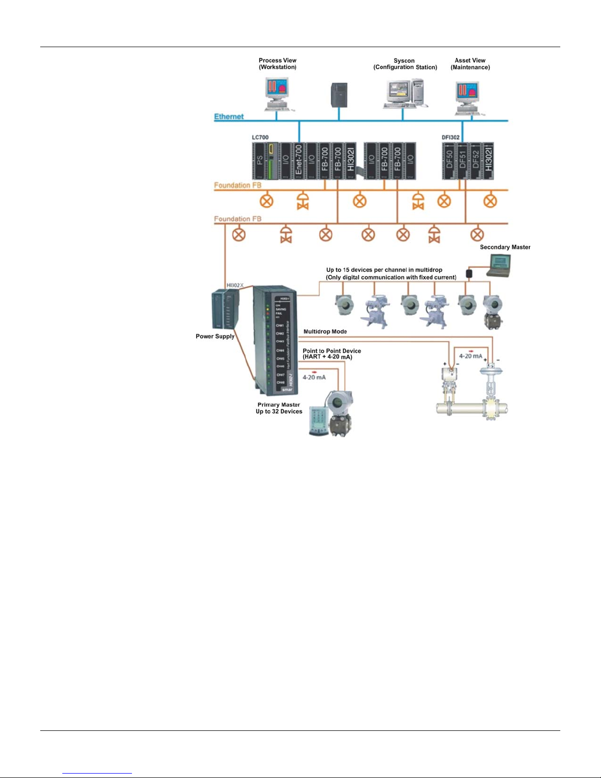
•The HI302 supports up to eight point-to-point HART devices or 32 HART devices in the multidrop
mode (4 devices per channel). Consult Smar about multidrop option;
•8 HART Master communications ports that can be configured as Primary or Secondary;
•1 FOUNDATION fieldbus H1 Channel;
•Fed via rack (5Vdc @400 mA);
•Device’s power supply should be from an external source;
•Input circuits 4-20 mA on HI302 – I (current conversion to FOUNDATION fieldbus );
•Output circuits 4-20 mA on HI302 – O (FOUNDATION fieldbus conversion to current).
There are three models for the HI302, according to the analog conversion needs:
•HI302 – N: only HART communication;
•HI302 – I : HART communication and conversion of eight 4-20 mA analog inputs to FOUNDATION
fieldbus;
•HI302 – O: HART communication and FOUNDATION fieldbus conversion to eight 4-20 mA analog
outputs.
1.1
HI302 - User’s Manual
1.2
Figure 1.2 – Hart/4-20 mA
Function Blocks
Several blocks were implemented to give the module the required functionality. The HI302 is
registered Fieldbus FOUNDATION equipment.
HART Communication Blocks
HCFG (HART Configuration and Diagnostic) – Concentrates general configuration parameters for
module operation, in addition to parameters on HART Communication performance and diagnostic.
It also concentrates parameters for analog circuit calibration.
HIRT (HART Information and Dynamic Data) – This block contains the main parameters, i.e., the
most commonly used, besides dynamic variables. All parameters related to universal commands
and some main “Common Practice” commands are found here. There should be one HIRT block for
each HART device installed. In normal operation, the HIRT block parameters show the HART
device variables, since there are mechanisms to keep the HI302 database updated. See the
Appendix A or the Function Blocks manual for further details. All of the HART dynamic variables
should be accessed through this block. The HIRT block has 8 output parameters which may be
used to make HART variables available in the control strategy, through the link with other blocks.
HUT (HART Universal Transducer), is equal to HIRT, but it does not has the 8 output parameters.
It allows supervising all HART variables. This block may be used in third part FOUNDATION fieldbus
systems that are not compatible with specific function blocks as the HIRT block.

Overview
1.3
HVT (HART Variable Template) – This block is a large collection of variables for general use. It is
now possible to access any HART instrument parameter, specially associated to specific HART
commands. To this effect, the module should get a configuration (HCD and HWPC blocks) to define
the specific instrument to be accessed, and how these commands will relate to each parameter on
the block. There is just one HVT block that should be shared among the devices when accessing
them. This configuration is already in the HI302’s Flash memory, when it is also possible to include
third party configurations according to the application’s needs.
HCD (HART Command Definition) – It contains the HART command description for each device
type or version. This description stores information needed by the module to communicate and the
data read on the HIRT or HVT blocks. The HCD blocks that defining the universal and the common
practice commands, as well as all commands specific to Smar instruments, are already stored in the
equipment’s memory and do not require any configuration from the user. See the Appendix B for
details. Configuration of specific commands for third party devices can be made through this block.
HWPC (HART Write Parameter Configuration) - This block stores information about all
parameters to be written in the instrument and mapped in the HVT block. See table with detailed
definitions on the Appendix A.
HBC (HART Bypass Communication) - This block allows directly the sending and receiving of
HART messages. Ideal for use with Hosts that access directly the HART devices through its
commands, using for example its DD. For more information see the BYPASS Communication Mode
section.
Analog Blocks
In order to support the analog circuits on HI302-I and HI302-O modules, use the AI/MAI or AO/MAO
blocks FOUNDATION fieldbus standard, respectively, to convert the analog 4-20 mA to FOUNDATION
fieldbus or FOUNDATION fieldbus to 4-20 mA.
AI – Analog Input
Analog input block FOUNDATION fieldbus standard. It allows associating its input to one of the analog
channels through the CHANNEL (1 to 8) parameter. It allows instantiate 8 blocks.
MAI – Multiple Analog Input
The MAI block FOUNDATION fieldbus standard makes available to the fieldbus network 8 variables of
the I/O subsystem through 8 output parameters, namely, OUT_1 to OUT_8. These parameters
correspond to the current value, in percentages, on the 8 analog inputs. The current values read
through this parameter may be linked to any other block, as part of the control strategy. It allows
instantiate 1 block.
AO – Analog Output
Analog output block FOUNDATION fieldbus standard. It allows associating its output to one of the
analog channels through the CHANNEL (1 to 8) parameter. It allows instantiate 8 blocks.
MAO – Multiple Analog Output
The MAO block FOUNDATION fieldbus standard makes available to the I/O subsystem 8 input
parameters, IN_1 to IN_8. These parameters correspond to the current value on the 8 analog
outputs. Through the MAO block, it is possible to control the current of each loop from another
block’s output that is part of the control strategy. It allows instantiate 1 block.

HI302 - User’s Manual
1.4
Technical Characteristics
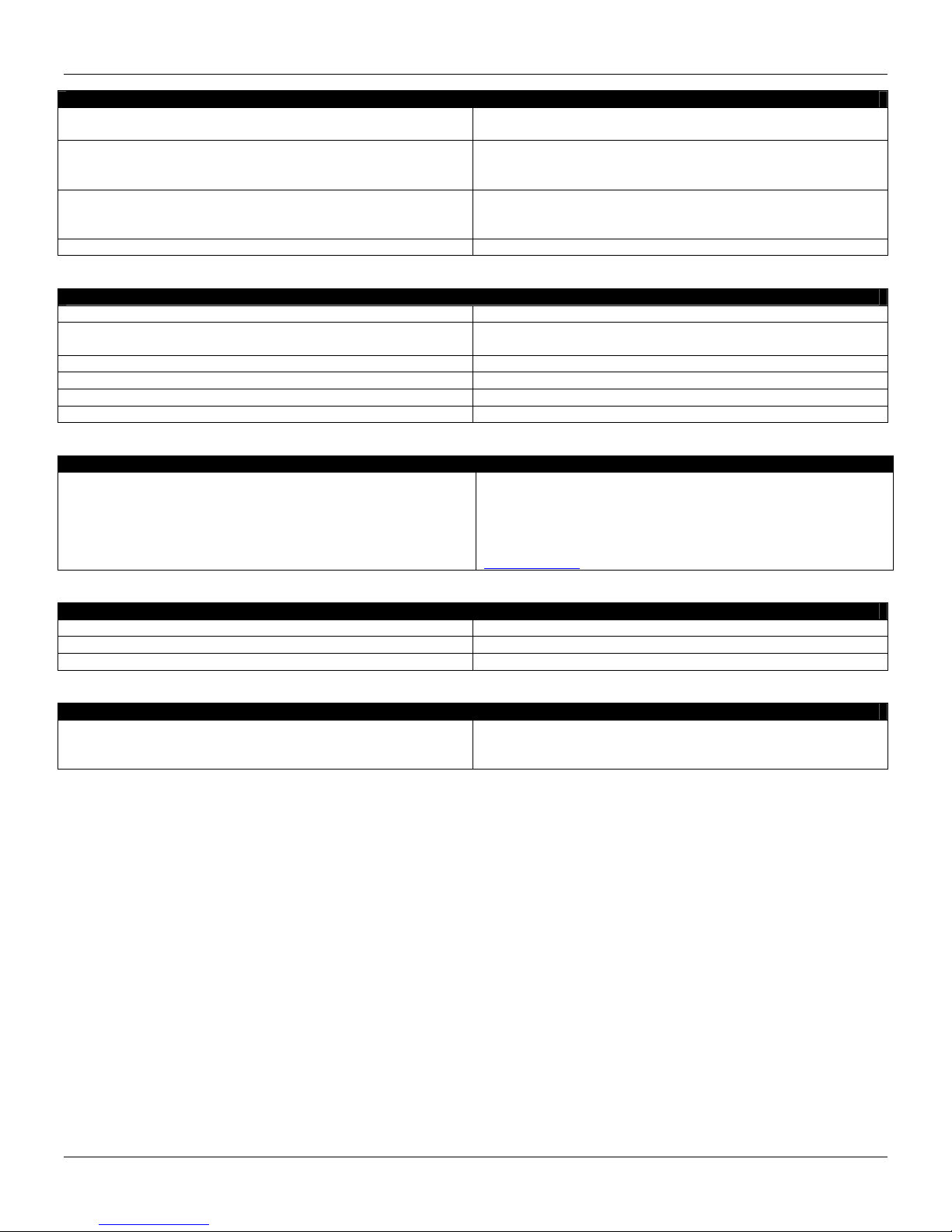
Power Supply
Input voltage 5 Vdc±5% @ 400 mA, maximum ripple of 20 mVpp, via rack
Maximum consumption 2 W
Indication Green LED – the device is powered
Memory
Operational system, applications and resident configurations 512 Kb – Super Flash
User’s configuration 32 Kb – EEPROM
General purpose memory 128 Kb - SRAM
Processor
Processor HC11 @ 16 MHz
Indication - Red LED - indicating fail
- Yellow LED - indicating saving in the EEPROM
HI302-I - Analog Input 4-20 mA
Input Impedance 250 Ω
A/D Converter
Range: 3.8 to 21 mA
A/D converter: 16 bits
Accuracy 0.05%1of range
Repeatability: ±0.01% of range.
Nonlinearity: ±0.01% of range
Temperature effect: ±0.001%/ºC.
Input filter Low pass filter, fc~10 Hz
Isolation
Field isolation through optical couplers and DC-DC converters,
1000 Vrms
Inputs are not isolated from each other
Power supply Supply of the HART devices through external power supply
Input Protections Polarity inversion, over voltage, transients, etc.
HI302-O - Analog Output 4-20 mA
D/A converter
Range: 3.8 to 21 mA
D/A converter: 12 bits
Accuracy: 0.05% of range
Repeatability: ±0.02% of range.
Nonlinearity: ±0.002%.
Temperature effect: ±0.00025%/ºC.
Isolation
Field isolation through optical couplers and DC-DC converters,
1000 Vrms
Outputs are not isolated from each other
Power supply Supply of the HART devices through external power supply
Protection Protected by TVS and zener diode
Current control Passive circuit, with current control: sink
Voltage on output terminals Maximum voltage 36 V (zener protection)
HI302-N - Only HART Communication
Isolation Isolation between channels 500Vrms
Coupler with the Loop Capacitive
1It can reach until ±0.2% under severity EMI conditions (Electromagnetic Interference).
Foundation is a trademark of Fieldbus Foundation.
Overview
1.5
HART
Supported Versions Supports HART devices versions 5. Consult Smar about its use
with other HART protocol versions.
Configurations
Resident configuration for Smar devices. Consult Smar about its
use with third part HART devices.
Allows configuration of specific HART commands
Communications ports
8 Master ports
Galvanic isolation of 1000 Vrms
Non multiplexed, that is, an independent UART per HART port
Indication Green LED – indicating the state of each port
Fieldbus
Controller Dedicated controller – Smar FB3050
Communications channel 1 channel H1, independent with DMA
Baud rate of 31.25 Kbps
MAU Passive MAU (not supplied by the bus) with 500 Vrms isolation
Physical layer ISA-S50.02.1992
Indication Green LED – indicating communications
Fieldbus Foundation Registration ITK 4.61
CE
CE Certification
The HI302-I, HI302-O and HI302-N models were tested and are
manufactured in agreement with the IEC-61326:2002 “Electrical
Equipment for Measurement, Control and Laboratory Use –
EMC Requirements” standard. The conformity declaration is
available for download in the page of the product in
www.smar.com.
Environment Conditions
Operation 0 to 60 °C
Storage -20 to 80 °C
Humidity 20 to 90% non condensed relative humidity
Dimensions
Dimensions and weight
142 x 40 x 126 mm
5.6 x 1.6 x 5.0 inch
Net weight: 450 g. With package: 500 g.

HI302 - User’s Manual
1.6
Chapter 2
2.1
INSTALLATION
This chapter deals with the main physical installation features, namely: mechanical and electrical
elements.
IMPORTANT
All comments or considerations made in this manual refer to HART communication using FSK
modulation (Frequency Shift Keying).
Installation of the HI302 modules
Mechanical Installation
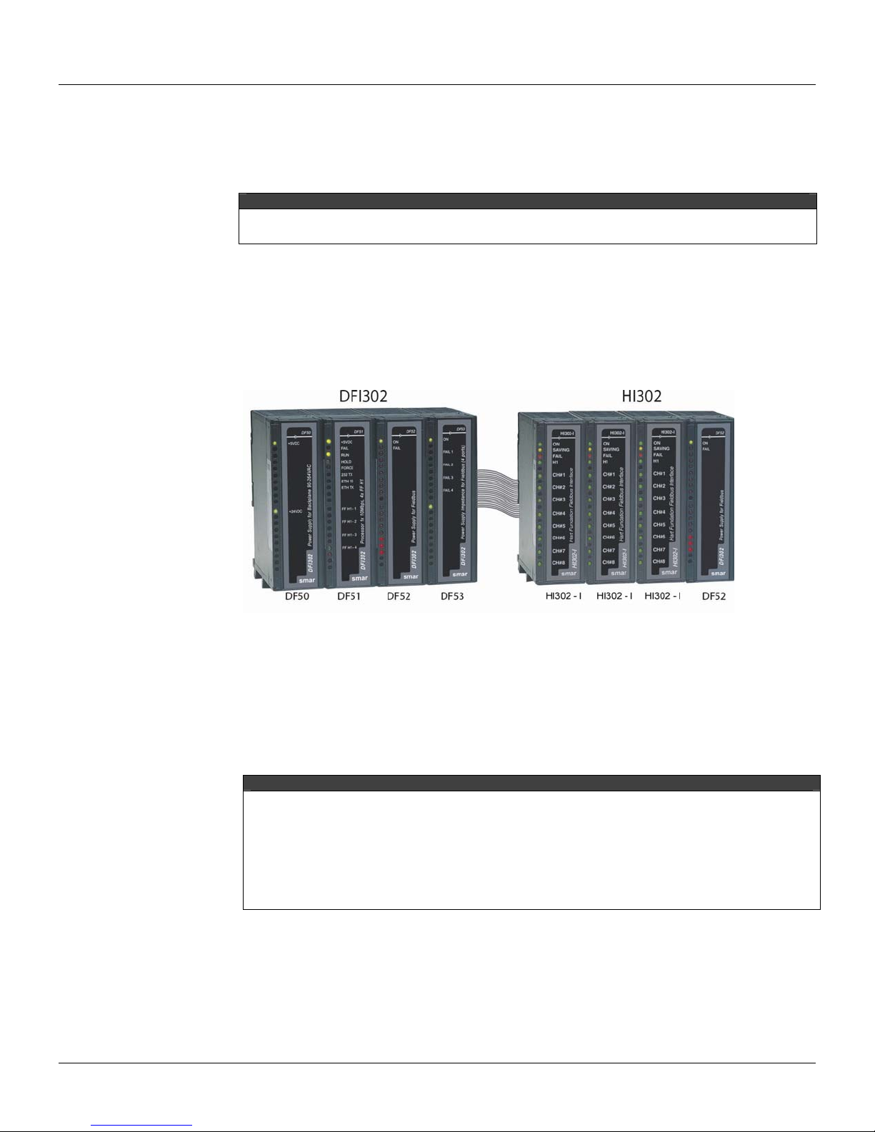
The HI302 modules are enclosed in the Smar standard plastic housing, like the LC700 and the
DFI302. Therefore, they are fully interchangeable on the standard racks. The picture below shows a
typical HI302 installation set:
Figure 2. 1 – HI302 modules in racks
The HI302 requires 5V @ 400 mA from the rack. You may use Smar DF50 power supply modules.
Besides providing a high quality feeding, they also provide a “Power Fail” signal to prevent power
failure or AC problems. However, the user can use another power supply provided it meets the
minimum requirement of quality and safety.
The other elements follow the same installation procedure as FOUNDATIONTM fieldbus and HART
devices. For further information on installation procedures, visit our site www.smar.com and
download a free copy of the any Smar device’s manuals.
ATTENTION ABOUT GROUNDING
The HI302 is equipment for industrial use that meets the rigorous international standards CE, FF,
HART, etc. For to offer the maximum of performance and safety to the users and the equipments
connected is fundamental that there is an appropriate grounding, according to NBR-5410, NBR-
5419, NBR-7117, IEC-200, IEEE-141 or IEEE-142 standards, or other more appropriate local
standard. All the power supply, racks, rail, and shield of cables should be grounded appropriately.
The grounding should be tested regularly, according to the maintenance plan of each installation,
to guarantee the maintenance of its electric properties. As suggestion the safety recommendations
of the NR 10 standards or another local standard on electric safety should be respected.
Electrical Connections
The minimum electrical connections for the HI302 are the power supply, normally connected to the
rack, to the connection with the H1 communications bus and to the connection with HART devices.
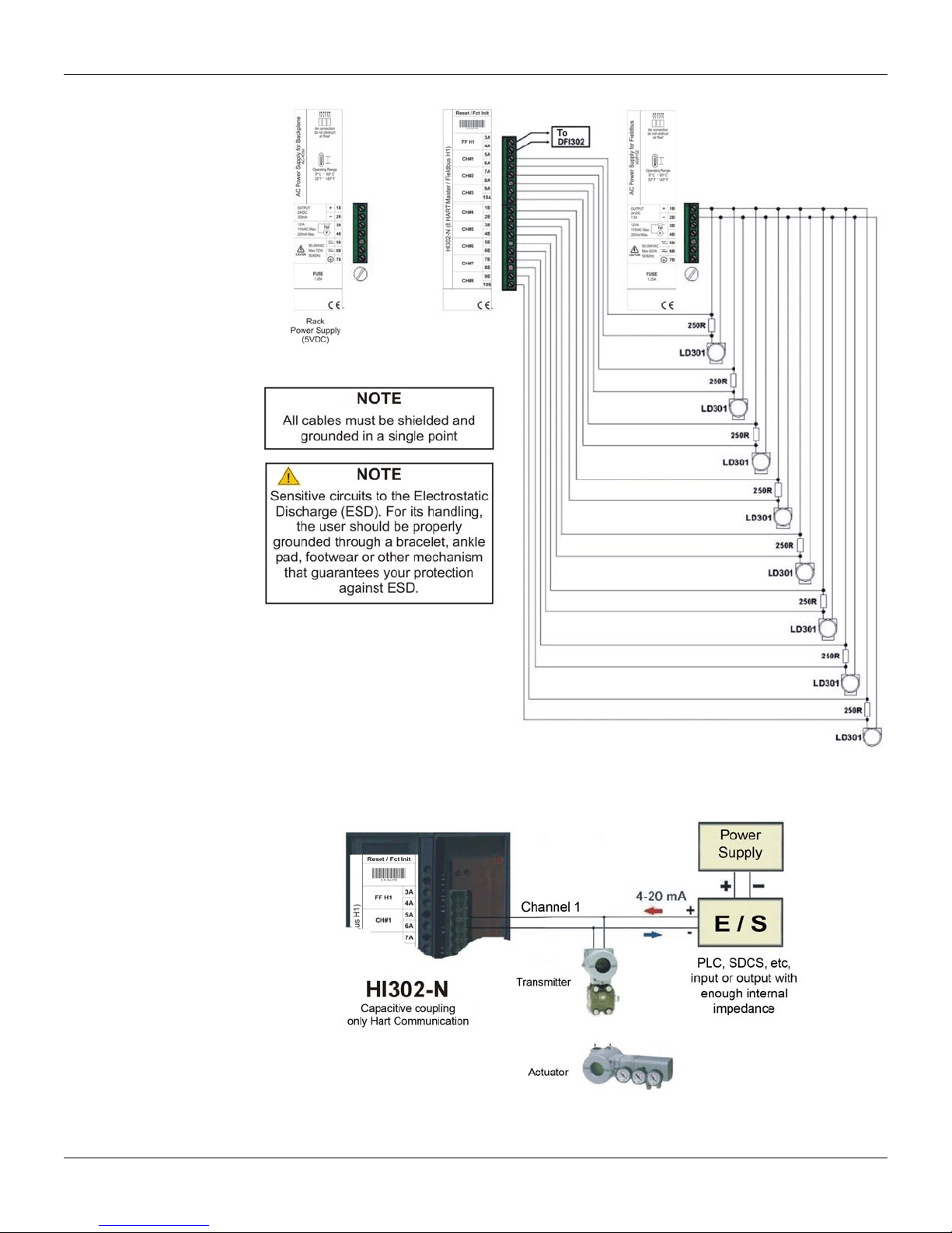
See the following figure for details. Since the HI302 does not supply the devices, it is necessary to
use a power supply for them. The DF50 can be used if the devices’ consumption does not exceed
300 mA (about 12 devices), otherwise the DF52 should be used as shown in the figure.

HI302 - User’s Manual
2.2
IMPORTANT
Since the HI302 H1 channel is a passive channel, it is not necessary to use the bus power supply
(DF53). For instance, if the DF51 channel is connected to the HI302 channel, they will
communicate normally. However, the BT302 terminator should always be used.
Figure 2. 2 – Example of necessary connections for the HI302
IMPORTANT
The figure above shows the connection of devices supplied by the same power supply module.
Remember that the HI302-I and HI302-O analog inputs and outputs are isolated from the field, not
from each other, that is, they have the negative terminal internally connected. The HI302-I or the
HI302-O can only be connected to an I/O system with a common ground.
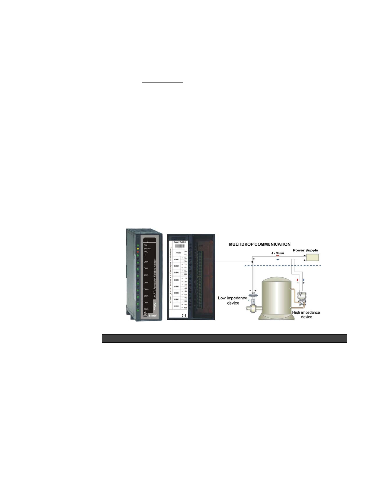
The following figure shows an example of an HI302-N connection focused on the HART
communication. In order to simplify the connection below, connect the HART channel in parallel to
the device, instead of connecting it in parallel to the resistor. Doing so, a common ground should be
used to decrease the wiring length. The connection below makes the channel independent from the
device’s power supply. Consult Smar for further details about this kind of link.
IMPORTANT
The HI302N channels are isolated from each other, thus they can be connected to different I/O
subsystems independently of the grounding or power supply used for the field devices.
Installation
2.3
Figure 2. 3 – Example of an HI302 connection
Figure 2. 4 – Connections between the HI302-N and a HART equipment in an I/O system
HI302 - User’s Manual
2.4
HART Device Installation
Now we will describe the main communication features regarding the device installation. For more
detailed information about the devices, please read the specific device’s manual. Concerning the
HART communication, consider that the superimposition of a modulated signal on an analog current
signal can deteriorate, if some precautions are not taken. It is important to mention that the HART
communication does not affect the 4-20 mA analog signal, since the average value of a FSK
modulated signal is zero. Thus, if the HART device is already installed, make sure that the minimum
impedance (250 Ω) is used and connect the HI302 channel in parallel to the device.
Device Types
Low Impedance Devices
Low impedance devices are typically signaling elements intended to receive current analog signals
or serve as master for a multidrop network. As an example of a low impedance device we can
mention the FY301 or input analog cards, such as HI302-I.
High Impedance Devices
High impedance devices control current, either as a mean of analog signaling or at a fixed level in a
multidrop topology. As an example of a high impedance device we can mention the LD301, TT301
or analog output cards such as HI302-O.
These concepts are fundamental when connecting different devices. For example, in the connection
shown below, it is not necessary to install a 250 Ωresistor for the HART communication. The
transmitter’s impedance should be enough. Although it may be necessary to install a resistor in
series with the power supply, just to achieve minimum impedance requirement (250 Ω). Each case
should be analyzed individually according to the equipment’s characteristics.
Figure 2. 5 – Connection without the 250Ωresistor
IMPORTANT
Whatever the topology used, it is important to keep a 250 Ωimpedance. In the previous figure, it is
not necessary to connect an impedance in series with the power supply, if the impedance read by
the HART channel is at least 250 Ω. In case the impedance is less than 250 Ω, increase its value
to the minimum requirement. The connection above allows the communication between the two
devices as long as the identification is done via TAG not via Polling Address.
HART Installation Topology
The HI302 complies with several applications, since the new ones to older installations, where it is
necessary to increase the HART device’s life span and preserve the investment with the gradual
introduction of the FOUNDATION fieldbus technology. Below are some examples of connections.
However, the applications are not limited to these examples and should be considered separately.
Installation
2.5
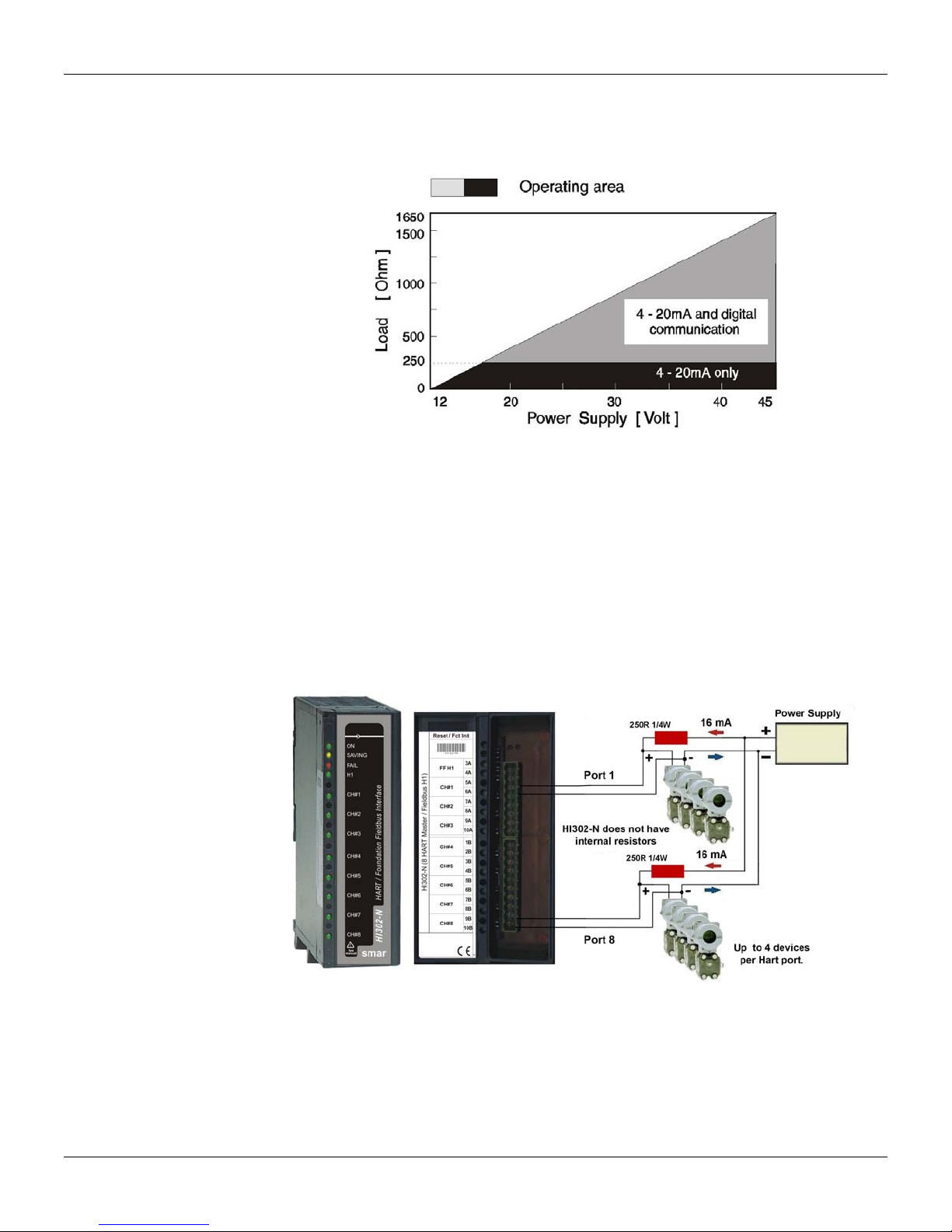
Supply Voltage vs. Total Loop Impedance
The total impedance of the devices connected to the pair of cables and the cable impedance should
be kept between the operation limits complying with the loop supply voltage. See the graph below:
Figure 2. 6 – Supply Voltage vs. Total Loop Impedance
Notice that it is very important to keep the minimum impedance (250 Ω) to allow HART
communication. Sometimes the voltage supply must be increased to ensure that the system is in the
operation area specially when associating devices on the same loop.
Example with HI302-N (without Analog Conversion)
This HI302 model has only HART communication and no circuit for analog conversion. The HI302-N
does not have an internal resistor, so it needs an external resistor or active impedance (PSI301) if
many devices are used. It is not necessary to use impedance or external resistor, if the loop has
already enough impedance to guarantee communication.
•Typical Multidrop
There are two ways to perform this connection. The resistor can be installed in series with the power
supply or in parallel to the HART channel. The first way is shown below:
Figure 2. 7 – Resistor in series with the power supply
•Multidrop with 4-20 mA enabled
Be careful with this topology because some types of I/O devices do not accept the connections
presented below, for example, the DCSs that feed the devices via internal power supply. The I/O
device must receive external power supply, like PLC cards or field devices. Despite the complexity,
this connection allows an improvement in the use of the HI302 channels, and due to the fact that the
current that flows in the loop is in the order of by the hundred mA, uses active impedance instead of

HI302 - User’s Manual
2.6
a simple resistor. See the next figure:
Figure 2. 8 – Parallel impedance with the HART channel
HI302-I (4-20 mA to FOUNDATION Fieldbus Conversion)
In this kind of topology, it is not necessary 250Ωexternal resistor connected in series with each
device, since there is a 4-20 mA sampling resistor in the HI302 analog board serial to the loop.
Figure 2. 9 – 4-20 mA FOUNDATION fieldbus conversion
Other manuals for HI302
1
Table of contents
Other SMAR Media Converter manuals


