SMAR IF302 Manual

I F302ME

web: www.smar.com/contactus.asp
www.smar.com
Specifications and information are subject to change without notice.
Up-to-date address information is available on our website.
smar

Kpvtqfwevkqp"
KKK"
INTRODUCTION
The IF302 is a converter mainly intended to interface analog transmitters to a FOUNDATION™
fieldbus network. The IF302 receives up to three current signal typically 4-20 mA or 0-20 mA, and
makes them available to Fieldbus system. The digital technology used in the IF302 enables an easy
interface between the field and the control room and it has several interesting features that reduce
considerably the installation, operation and maintenance costs.
The IF302 is part of SMAR's complete 302 line of FOUNDATION™ fieldbus devices.
FOUNDATION™ fieldbus, is not only a replacement for 4-20 mA or intelligent/smart transmitter
protocols, it contains much more. FOUNDATION™ fieldbus is a complete system enabling distribution
of the control function on equipment in the field.
Some of the advantages of bi-directional digital communications are known from existing smart
transmitter protocols: Higher accuracy, multi-variable access, remote configuration and diagnostics,
and multi-dropping of several devices on a single pair of wires.
Those protocols were not intended to transfer control data, but maintenance information. Therefore
they were slow and not efficient enough to be used as control network.
The main requirements for Fieldbus were to overcome these problems. Closed loop control with
performance like a 4-20 mA system requires higher speed. Since higher speed means higher power
consumption, this clashes with the need for intrinsic safety. Therefore a moderately high
communication speed was selected, and the system was designed to have a minimum of
communication overhead. Using scheduling, the system controls variable sampling, algorithm
execution and communication to optimize the usage of the network, not loosing time. Thus, high
closed loop performance is achieved.
Using Fieldbus technology, with its capability to interconnect several devices, very large control
schemes can be constructed. In order to be user friendly the function block concept was introduced
(users of SMAR CD600 should be familiar with this, since it was implemented several years ago).
The user may now easily build complex control strategies. Another advantage is added flexibility;
the control strategy may be edited without having to rewire or change any hardware.
The IF302, like the rest of the 302 family, has several Function Blocks built in, like PID controller,
Input Selector, Arithmetic, Signal Characterizer and Flow Totalization. These useful blocks eliminate
the need for separate devices and reduce communication and therefore decreasing dead-time and
making the control tighter, not to mention the reduction in cost. Other function blocks are also
available, allowing flexibility in control strategy implementation.
The need for implementation of Fieldbus in small as well as large systems was considered when
developing the entire 302 line of Fieldbus devices. They have the common features of being able to
act as a master on the network and be configured locally using a magnetic tool, eliminating the need
for a configurator or console in many basic applications.
Get the best result of the IF302 by carefully reading these instructions.
This product is protected by US patent number 5,706,007.

KH524"⁄"Qrgtcvkqp"cpf"Ockpvgpcpeg"Kpuvtwevkqp"Ocpwcn"
KX"
NOTE
This Manual is compatible with version 3.XX, where 3 denote software version and XX software release. The
indication 3.XX means that this manual is compatible with any release of software version 3.
"
Waiver of responsibility
The contents of this manual abides by the hardware and software used on the current equipmen
t
version. Eventually there may occur divergencies between this manual and the equipment. The
information from this document are periodically reviewed and the necessary or identified corrections
will be included in the following editions. Suggestions for their improvement are welcome.
Warning
For more objectivity and clarity, this manual does not contain all the detailed information on the
product and, in addition, it does not cover every possible mounting, operation or maintenance
cases.
Before installing and utilizing the equipment, check if the model of the acquired equipment complies
with the technical requirements for the application. This checking is the user’s responsibility.
If the user needs more information, or on the event of specific problems not specified or treated in
this manual, the information should be sought from Smar. Furthermore, the user recognizes that the
contents of this manual by no means modify past or present agreements, confirmation or judicial
relationship, in whole or in part.
All of Smar’s obligation result from the purchasing agreement signed between the parties, which
includes the complete and sole valid warranty term. Contractual clauses related to the warranty are
not limited nor extended by virtue of the technical information contained in this manual.
Only qualified personnel are allowed to participate in the activities of mounting, electrical connection,
startup and maintenance of the equipment. Qualified personnel are understood to be the persons
familiar with the mounting, electrical connection, startup and operation of the equipment or othe
r
similar apparatus that are technically fit for their work. Smar provides specific training to instruct and
qualify such professionals. However, each country must comply with the local safety procedures,
legal provisions and regulations for the mounting and operation of electrical installations, as well as
with the laws and regulations on classified areas, such as intrinsic safety, explosion proof, increased
safety and instrumented safety systems, among others.
The user is responsible for the incorrect or inadequate handling of equipments run with pneumati
c
or hydraulic pressure or, still, subject to corrosive, aggressive or combustible products, since thei
r
utilization may cause severe bodily harm and/or material damages.
The field equipment referred to in this manual, when acquired for classified or hazardous areas, has
its certification void when having its parts replaced or interchanged without functional and approval
tests by Smar or any of Smar authorized dealers, which are the competent companies for certifying
that the equipment in its entirety meets the applicable standards and regulations. The same is true
when converting the equipment of a communication protocol to another. In this case, it is necessar
y
sending the equipment to Smar or any of its authorized dealer. Moreover, the certificates are
different and the user is responsible for their correct use.
Always respect the instructions provided in the Manual. Smar is not responsible for any losses
and/or damages resulting from the inadequate use of its equipments. It is the user’s responsibility to
know and apply the safety practices in his country.
"
"

Vcdng"qh"Eqpvgpvu"
X"
TABLE OF CONTENTS
UGEVKQP"3"/"KPUVCNNCVKQP"0000000000000000000000000000000000000000000000000000000000000000000000000000000000000000000000000000000000000000000000"303"
GENERAL............................................................................................................................................................................1.1
MOUNTING..........................................................................................................................................................................1.1
ELECTRIC WIRING .............................................................................................................................................................1.1
TOPOLOGY AND NETWORK CONFIGURATION ..............................................................................................................1.3
INPUT WIRING ....................................................................................................................................................................1.5
UGEVKQP"4"/"QRGTCVKQP"000000000000000000000000000000000000000000000000000000000000000000000000000000000000000000000000000000000000000000000000000"403"
FUNCTIONAL DESCRIPTION – ELECTRONICS ...............................................................................................................2.1
UGEVKQP"5"/"EQPHKIWTCVKQP"000000000000000000000000000000000000000000000000000000000000000000000000000000000000000000000000000000000000000000"503"
TRANSDUCER BLOCK .......................................................................................................................................................3.1
HOW TO CONFIGURE A TRANSDUCER BLOCK..............................................................................................................3.1
TERMINAL NUMBER ..........................................................................................................................................................3.1
PRIMARY VALUE STATUS.................................................................................................................................................3.2
CURRENT TRIM..................................................................................................................................................................3.2
VIA LOCAL ADJUSTMENT..................................................................................................................................................3.4
DISPLAY TRANSDUCER BLOCK .......................................................................................................................................3.5
DEFINITION OF PARAMETERS AND VALUES..................................................................................................................3.5
PROGRAMMING USING LOCAL ADJUSTMENT ...............................................................................................................3.8
J1 JUMPER CONNECTIONS ..............................................................................................................................................3.9
W1 JUMPER CONNECTIONS.............................................................................................................................................3.9
UGEVKQP"6"/"OCKPVGPCPEG"0000000000000000000000000000000000000000000000000000000000000000000000000000000000000000000000000000000000000000000000"603"
GENERAL............................................................................................................................................................................4.1
TROUBLESHOOTING .........................................................................................................................................................4.1
DISASSEMBLY PROCEDURE ............................................................................................................................................4.2
REASSEMBLE PROCEDURE .............................................................................................................................................4.2
BOARDS INTERCHANGEABILITY......................................................................................................................................4.2
EXPLODED VIEW ...............................................................................................................................................................4.3
ACCESSORIES ...................................................................................................................................................................4.3
SPARE PARTS LIST ...........................................................................................................................................................4.4
UGEVKQP"7"/"VGEJPKECN"EJCTCEVGTKUVKEU"0000000000000000000000000000000000000000000000000000000000000000000000000000000000000000"703"
ORDERING CODE ..............................................................................................................................................................5.2
CRRGPFKZ"C"/"EGTVKHKECVKQPU"KPHQTOCVKQP"000000000000000000000000000000000000000000000000000000000000000000000000000000000000"C03"
EUROPEAN DIRECTIVE INFORMATION...........................................................................................................................A.1
HAZARDOUS LOCATIONS GENERAL INFORMATION.....................................................................................................A.1
HAZARDOUS LOCATIONS APPROVALS ..........................................................................................................................A.2
CSA (CANADIAN STANDARDS ASSOCIATION)................................................................................................................................... A.2
FM APPROVALS (FACTORY MUTUAL)................................................................................................................................................. A.3
NEMKO (NORGES ELEKTRISKE MATERIELKONTROLL) ................................................................................................................... A.3
EXAM (BBG PRÜF - UND ZERTIFIZIER GMBH) ................................................................................................................................... A.3
CEPEL (CENTRO DE PESQUISA DE ENERGIA ELÉTRICA) ............................................................................................................... A.4
IDENTIFICATION PLATE CONTROL DRAWING................................................................................................................A.5
CONTROL DRAWING .........................................................................................................................................................A.7
CRRGPFKZ"D"⁄"UTH"⁄"UGTXKEG"TGSWGUV"HQTO"00000000000000000000000000000000000000000000000000000000000000000000000000000000000"D03"
RETURNING MATERIALS...................................................................................................................................................B.2

KH524"⁄"Qrgtcvkqp"cpf"Ockpvgpcpeg"Kpuvtwevkqp"Ocpwcn"
XK"
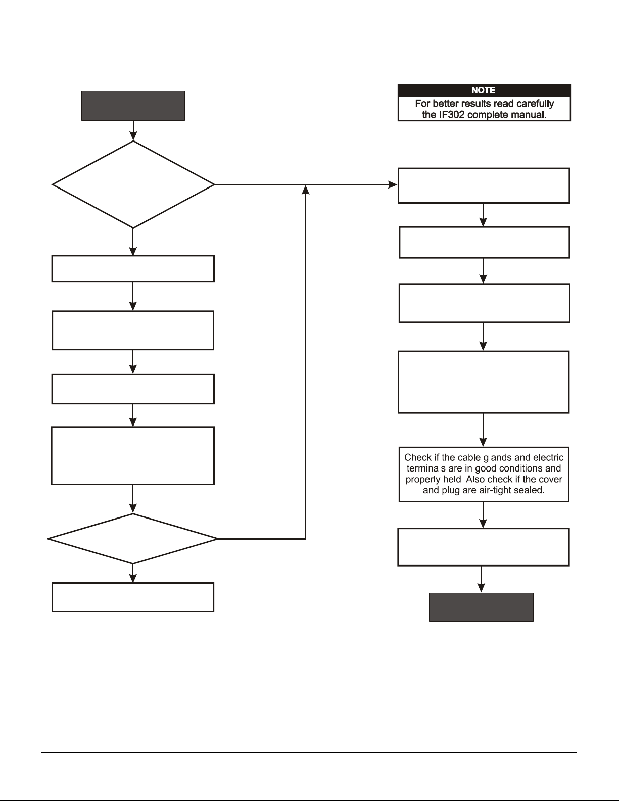
Kpuvcnncvkqp"Hnqyejctv"
"
XKK"
Kpuvcnncvkqp"Hnqyejctv"
Was the converter
configured on the bench
to match the application?
Configure the engineering unit.
Configure the terminal(s)
and input scale(s) .
(Section 3 - Calibration)
Configure the LCD reading.
(Section 3 - Configuration)
Simulate the value(s) in the 4 a
20 mA input and verify the
signal(s) in Fieldbus.
Start
No
Yes
Is the indication correct?
See section 4 - Maintenance
OK
Install the converter on the field
following the instructions below.
Check the area classification
and its practices.
Install the (mechanically
and electrically) according to the
application after checking the best
position for the LCD
(Section 4 - Maintenance).
converter
Install the preferably
on wether-protected areas.
converter
Energize the properly.
IF302 needs a external power supply
for supply the equipment .
converter
4 - 20 mA
No
Yes

KH524"⁄"Qrgtcvkqp"cpf"Ockpvgpcpeg"Kpuvtwevkqp"Ocpwcn"
XKKK"

Section 1
1.1
INSTALLATION
General
NOTE
The installation carried out in hazardous areas should follow the recommendations of the IEC60079-14
standard.
The overall accuracy of measurement and control depends on several variables. Although the
converter has an outstanding performance, proper installation is essential, in order to maximize its
performance.
Among all factors, which may affect converter accuracy, environmental conditions are the most
difficult to control. There are, however, ways of reducing the effects of temperature, humidity and
vibration.
Locating the converter in areas protected from extreme environmental changes can improve the
converter performance.
In warm environments, the converter should be installed to avoid as much as possible, direct
exposure to the sun. Installation close to lines and vessels subjected to high temperatures should
also be avoided.
Use of sunshades or heat shields to protect the converter from external heat sources should be
considered, if necessary.
Humidity is fatal to electronic circuits. In areas subjected to high relative humidity, the O-rings for the
electronics cover must be correctly placed. Removal of the electronics cover in the field should be
reduced to the minimum necessary, since each time it is removed the circuits are exposed to the
humidity. The electronic circuit is protected by a humidity proof coating, but frequent exposures to
humidity may affect the protection provided. It is also important to keep the covers tightened in
place. Every time they are removed, the threads are exposed to corrosion, since painting cannot
protect these parts. Code-approved sealing methods on conduit entering the converter should be
employed.
Mounting
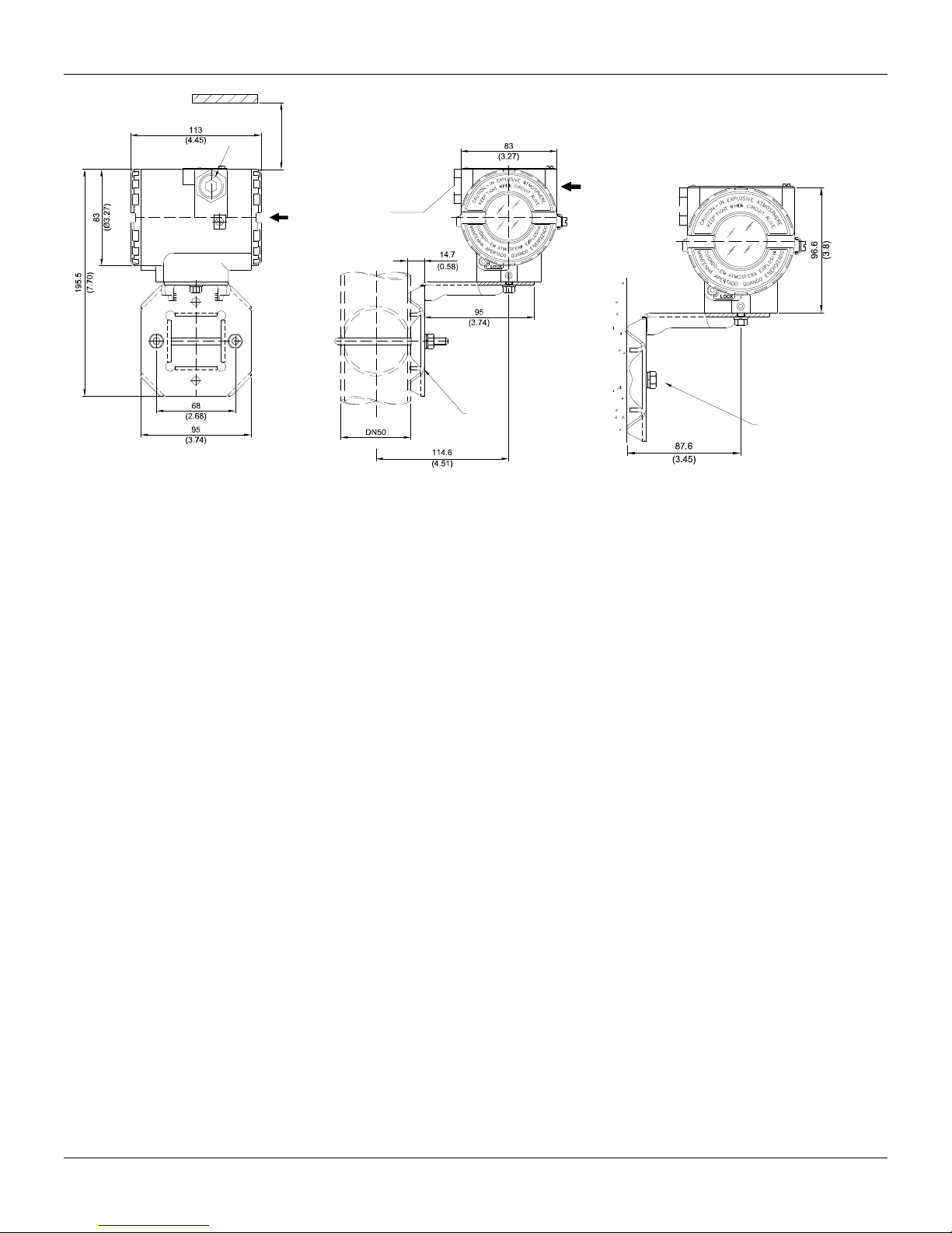
Using the bracket, the mounting may be done in several positions, as shown on Figure 1.3 -
Dimensional Drawing and Mounting Positions.
For better visibility, the digital indicator may be rotated in steps of 90(See Section 4 - Maintenance
Procedures).
Electric Wiring
Access the wiring block by removing the Electrical Connection Cover. This cover can be locked
closed by the cover locking screw (See Figure 1.1 - Cover Locking). To release the cover, rotate the
locking screw clockwise.
Cable access to wiring connections is obtained by one of the two conduit outlets. Conduit threads
should be sealed by means of code-approved sealing methods. The unused outlet connection
should be plugged accordingly.

IF302 - Operation and Maintenance Instruction Manual
1.2
COVER
LOCKING
SCREW
Figure 1.1 - Cover Locking
For convenience there are three ground terminals: one inside the cover and two externals, located
close to the conduit entries.
The wiring block has screws, on which fork or ring type terminals can be fastened, see Figure 1.2 -
Terminal Block.
GROUND
TERMINA
L
POWE
R
SUPPLY
TERMINALS
COMUNICATION
TERMINALS
Figure 1.2 - Terminal Block
The IF302 uses the 31.25 kbit/s voltage mode option for the physical signaling. All other devices on
the same bus must use the same signaling. 12 to 16 devices can be connected in parallel along the
same pair of wires.
Various types of Fieldbus devices may be connected on the same bus.
The IF302 is powered via the bus. The limit for such devices is 16 for one bus (one segment) for
non-intrinsically safe requirement.
In hazardous area, the number of devices may be limited by intrinsically safe restrictions.
The IF302 is protected against reverse polarity, and can withstand ±35 VDC without damage.
NOTE
Please refer to the General Installation, Operation and Maintenance Manual for more details.
Installation
1.3
ALLOW 150 MM MINIMUM FOR LOCAL
ZERO AND SPAN ADJUSTMENT WITH
MAGNETIC TOOL.
COMMUNICATIONS
TERMINAL
PLUG
CONDUIT
CONNECTION
MOUNTING BRACKET
PIPE 2"
PLUG
WALL OR
PANEL MOUNTING
FOR WALL MOUNTING
2 EXPANSION ANCHOR -
2 HEXAGON SCREW - S8
3/16”X70
2 BOLTAND NUTS - 1/4”X30
NOT INCLUDED
FOR PANEL MOUNTING
Figure 1.3 - Dimensional Drawing and Mounting Positions
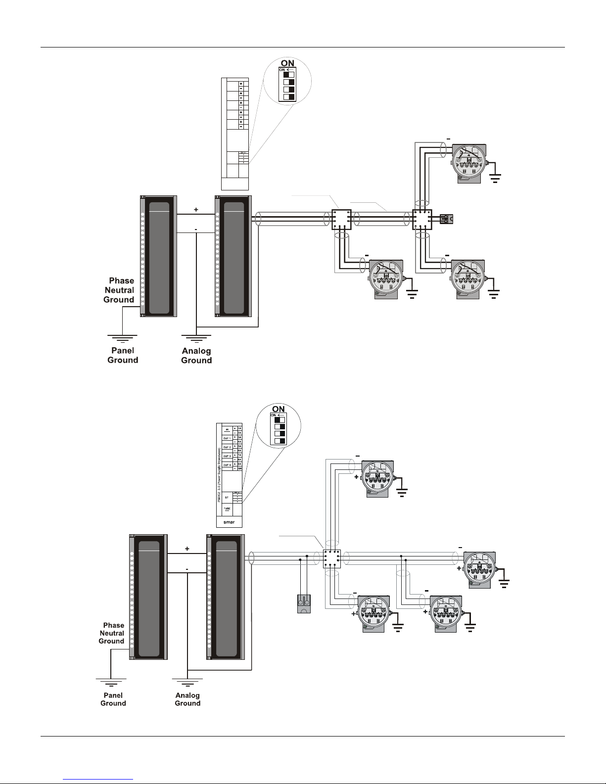
Topology and Network Configuration
Bus topology (See Figure 1.4 - Bus Topology) and tree topology (See Figure 1.5 - Tree Topology
Configuration) are supported. Both types have a trunk cable with two terminations. The devices are
connected to the trunk via spurs. The spurs may be integrated in the device giving zero spur length.
A spur may connect more than one device, depending on the length. Active couplers may be used
to extend spur length.
Active repeaters may be used to extend the trunk length.
The total cable length, including spurs, between any two devices in the Fieldbus should not exceed
1900m.
IF302 - Operation and Maintenance Instruction Manual
1.4
Spur
Terminator
Spur
Spur
Shield
Junction
Box
Terminator
Enabled
++
+
smar
FUSE
2,5A
PSI302 3.0 (Power Supply Impedance)
1A
2A
3A
4A
IN
24VDC
BT
OUT 1
Fieldbus H1
OUT 2
Fieldbus H1
OUT 3
Fieldbus H1
OUT 4
Fieldbus H1
5A
6A
7A
8A
9A
10A
PS302
FAIL
smar
ON
PSI302
FAIL 1
FAIL 2
FAIL 3
FAIL 4
smar
ON
Figure 1.4 - Bus Topology
Terminator
Enabled
Junction
Box
Coupler
PS302
FAIL
smar
ON
PSI302
FAIL 1
FAIL 2
FAIL 3
FAIL 4
smar
ON
Figure 1.5 - Tree Topology Configuration
Installation
1.5
Input Wiring
The IF302 accepts up to three current inputs in the range 0-20 mA or 4-20 mA. The three inputs
have a common ground and they are protected from reverse polarity signal. The inputs should be
connected as per Figure 1.6 - Input Wiring.
IF
302
FIELDBUS
4 a 20mA
TRANSMITTER 1
TRANSMITTER 2
TRANSMITTER 3
POWER
SUPPLY
+
_
+
+
+
+
_
1
2
3
4
Figure 1.6 - Input Wiring
Note that IF302 can operate with 0-20 mA or 4-20mA transmitters (See Figure 1.7 - Connection).
CHANNEL1
11
22
+
33
44
CHANNEL 2
4-20mA
CHANNEL 3
COMMON
CO
NNE
C
TI
O
N
+
Power
Supply
-
TR
TR
-
+
-
+
TR
-
+
TR = Transmitter
-
-
+
-
0-20mA
0-20mA
0-20mA
+
4-wire 0-20mA Transmitters or
0-20mA Current Generator
CHANNEL1
CHANNEL 2
CHANNEL
3
COMMON
Figure 1.7 - Connection
Avoid routing input wiring close to power cables or switching equipment.
WARNING
Apply in the inputs of the conversor only current levels. Don't apply tension levels, because the shunt resistors
are of 100R 1W and tension above 10 Vdc it can damage them.

IF302 - Operation and Maintenance Instruction Manual
1.6
Installation in Hazardous Areas
WARNING
Explosions could result in death or serious injury, besides financial damage. Installation of this
converter in explosive areas must be carried out in accordance with the local standards and the
protection type adopted .Before continuing the installation make sure the certificate parameters are
In accordance with the classified area where the equipment will be installed.
The instrument modification or parts replacement supplied by other than authorized representative
of Smar is prohibited and will void the certification.
The converters are marked with options of the protection type. The certification is valid only when
the protection type is indicated by the user. Once a particular type of protection is selected, any
other type of protection can not be used.
The electronic housing and the sensor installed in hazardous areas must have a minimum of 6 fully
engaged threads. Lock the housing using the locking screw (Figure 1.1).
The cover must be tighten with at least 8 turns to avoid the penetration of humidity or corrosive
gases. The cover must be tighten until it touches the housing. Then, tighten more 1/3 turn (120) to
guarantee the sealing. Lock the covers using the locking screw (Figure 1.1).
Consult the Appendix A for further information about certification.
Explosion/Flame Proof
WARNING
In Explosion-Proof installations the cable entries must be connected or closed using metal cable
gland and metal blanking plug, both with at least IP66 and Ex-d certification.
The standard plugs provided by Smar are certified according to CEPEL certificate. If the plug
needs to be replaced, a certified plug must be used.
The electrical connection with NPT thread must use waterproofing sealant. A non-hardening
silicone sealant is recommended.
For NEMKO ATEX certificate please to follow the installation guidelines in hazardous locations
below: Group II Category 2G, Ex d, Group IIC, Temperature Class T6, EPL Gb U = 28VDC
Ambient Temperature: -20 to 60ºC for T6
Environmental Protection: IP66/687 or IP66W/687W
The electrical connection available are ½ - 14NPT and M20x1,5.
Cable entries must be connected or closed using metal cable gland and metal blanking plug,
both with at least IP66 and Ex-d certification or any appropriate ATEX approved metal cable
gland and metal blanking plug. Do not remove the transmitter covers when power is ON.
Intrinsically Safe WARNING
In hazardous zones with intrinsically safe or non-incendive requirements, the circuit entity
parameters and applicable installation procedures must be observed.
To protect the application the transmitter must be connected to a barrier. Match the parameters
between barrier and the equipment (Consider the cable parameters). Associated apparatus
ground bus shall be insulated from panels and mounting enclosures. Shield is optional. If used, be
sure to insulate the end not grounded. Cable capacitance and inductance plus Ci and Li must be
smaller than Co and Lo of the associated Apparatus.
It is not recommended to remove the transmitter cover when the power is ON.

Section 2
2.1
OPERATION
The IF302 accepts signals from mA generators such as most conventional transmitters. It is
therefore ideal for interfacing existing equipment to a Fieldbus system.
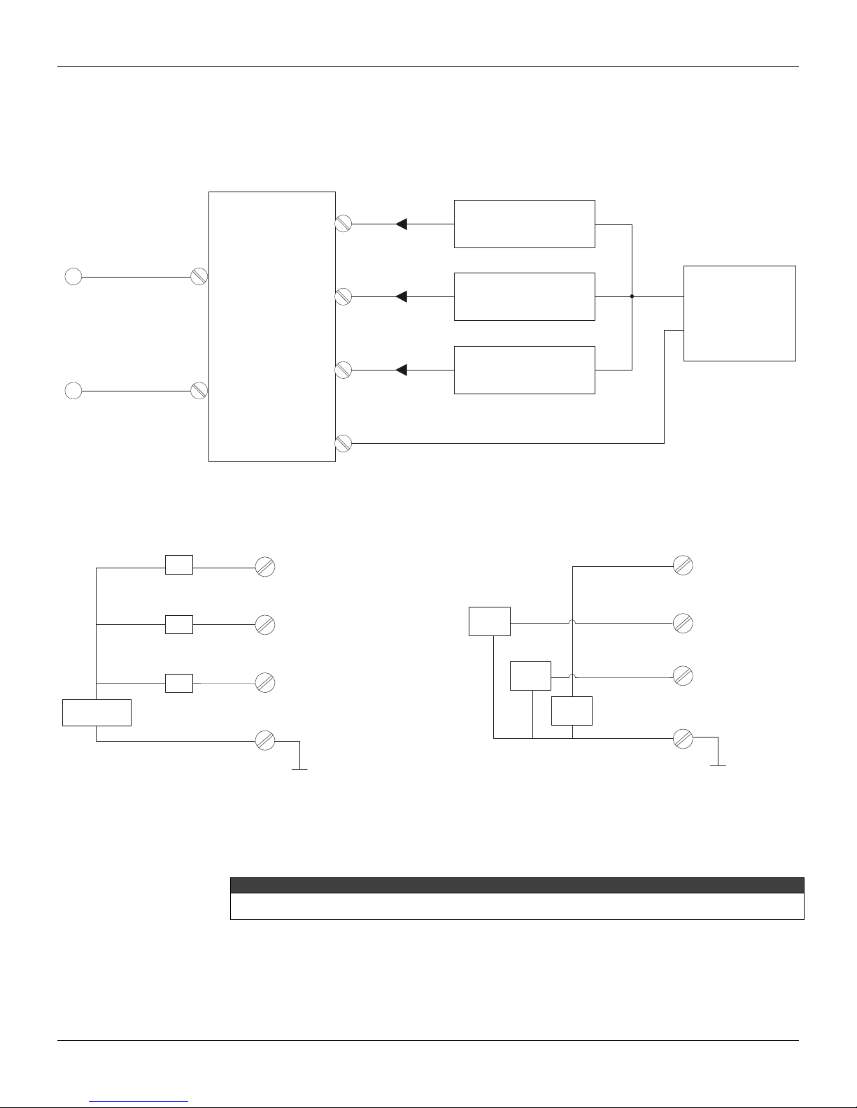
Functional Description – Electronics
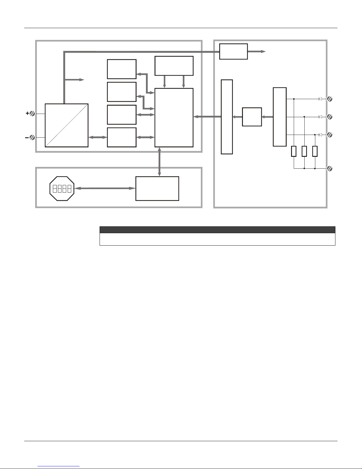
Refer to the block diagram (See Figure 2.1 - IF302 Block Diagram). The function of each block is
described below.
MUX Multiplexer
The MUX multiplexes the input terminals to ensure that all three channels reach the A/D converter.
A/D Converter
The A/D converts the input signals to a digital format for the CPU.
Signal Isolator
Its function is to isolate the data signal between the input and the CPU.
(CPU) Central Processing Unit, RAM and FLASH
The CPU is the intelligent portion of the converter, being responsible for the management and
operation of block execution, self-diagnostics and communication. The program is stored in Flash
memory. For temporary storage of data there is a RAM. The data in the RAM is lost if the power is
switched off, however the device also has a nonvolatile EEPROM where data that must be retained
are stored. Examples of such data are: calibration, configuration and identification data.
Communication Controller
It monitors line activity, modulates and demodulates the signal from network line.
Power Supply
Takes power of the loop-line to power the converter circuitry.
Power Isolation
Just like the signals from the input section, the power to the input section must be isolated.
Display Controller
Receives data from the CPU and drives the Liquid Crystal Display.
Local Adjustment
They are two switches that are magnetically activated. They can be activated by the magnetic tool
without mechanical or electrical contact.
IF302 – Operation and Maintenance Instruction Manual
2.2
SUPPLY
FLASH
FIRMWARE
DOWLOAD
INTERFACE
RAM
MODEM
CPU
EEPROM
LOCAL ADJUST
POWER
ISOLATION
S
I
G
N
A
L
I
S
O
L
A
T
I
O
N
M
U
X
A/D
1
2
3
4
(*) Resistor Shunt
3 x 100
MAIN CIRCUIT BOARD INPUT CIRCUIT BOARD
DISPLAY BOARD
POWER
SUPPLY
DISPLAY
CONTROLLER
SIGNAL
SHAPING
Figure 2.1 - IF302 Block Diagram
* WARNING
Apply in the inputs of the conversor only current levels. Don't apply tension levels, because the shunt
resistors are of 100R 1W and tension above 10 Vdc it can damage them.

Section 3
3.1
CONFIGURATION
One of the many advantages of Fieldbus is that device configuration is independent of the
configurator. The IF302 may be configured by a third party terminal or operator console.
The IF302 contains three input transducer blocks, one resource block, one display transducer block
and function blocks.
Function Blocks are not covered in this manual. For explanation and details of function blocks, see
the “Function Blocks Manual”.
Transducer Block
Transducer block insulates function block from the specific I/O hardware, such as sensors and
actuators. Transducer block controls access to I/O through manufacturer specific implementation.
This permits the transducer block to execute as frequently as necessary to obtain good data from
sensors without burdening the function blocks that use the data. It also insulates the function blocks
from the manufacturer specific characteristics of certain hardware.
By accessing the hardware, the transducer block can get data from I/O or passing control data to it.
The connection between Transducer block and Input/Output Function blocks is called channel.
Normally, transducer blocks perform functions, such as linearization, characterization, temperature
compensation, control and exchange data to/from hardware.
How to Configure a Transducer Block
The transducer block has an algorithm, a set of contained parameters and a channel connecting it to
a function block.
The algorithm describes the behavior of the transducer as a data transfer function between the I/O
hardware and other function block. The set of contained parameters, it means, you are not able to
link them to other blocks, defines the user interface to the transducer block. They can be divided into
Standard and Manufacturer Specific.
The standard parameters will be present for such class of device, as pressure, temperature,
actuator, etc., whatever is the manufacturer. Oppositely, the manufacturers specific ones are
defined only by its manufacturer. As common manufacturer specific parameters, we have calibration
settings, material information, linearization curve, etc.
When you perform a standard routine as a calibration, you are conducted step by step by a method.
The method is generally defined as guide line to help the user to make common tasks. The
SYSCON configurator identifies each method associated to the parameters and enables the
interface to it.
Terminal Number
The terminal number, which references a physical input, which is sent internally from the specified
transducer output to function block.
It starts at one (1) for transducer number one until three (3) for transducer number three.
The channel number of the AI block is related to the transducer’s terminal number. Channel number
1, 2, 3 corresponds bi-univocally to the terminal block with the same number. Therefore, all the user
has to do is to select combinations: (1.1), (2.2), (3,3) for (CHANNEL, BLOCK).

IF302 - Operation and Maintenance Instruction Manual
3.2
Primary Value Status
The status of the Primary Value can follow the NAMUR NE 43 as showed bellow:
3.80 mA < input < 20.5 mA GOOD
input = 3.80 mA or input = 20.5 UNCERTAIN
input <= 3.6 mA or input >= 21.0 mA BAD
To disable this feature, just write a number different from 4 or 20 in the Transducer xd_scale
parameter.
Current Trim
The IF302 provides the capability of making a trim in the input channels, if necessary.
A trim is necessary if the indicator reading of the transducer block output differs from the actual
physical output. The reason may be:
The user's current meter differs from the factory standard.
The converter had its original characterization shifted by over-load or by long term drift.
The user can check the calibration of the transducer output by measuring the actual current in the
input and compare it with the device’s indication (of course an appropriate meter shall be used). If a
mismatch is detected, a trim can be done.
Trim can be done in two points:
Lower Trim: Is used to trim the output at the lower range.
Upper Trim: Is used to trim the output at the upper range.
These two points define the linear characteristic of the output. Trim in one point is independent from
the other.
There are at least two ways of doing the trim: using local adjustment or using SYSCON (the System
Configurator from SMAR).
When doing the trim, make sure you are using an appropriate meter (with the necessary accuracy).
Via SYSCON
The channel number of the AI block is related to the transducer’s terminal block number. Channel
number 1,2,3 corresponds bi-univocally to the terminal block with the same number. Therefore, all
the user has to do is to select combinations: (1,1), (2,2), (3,3), for (CHANNEL, TERMINAL
NUMBER).

Configuration
3.3
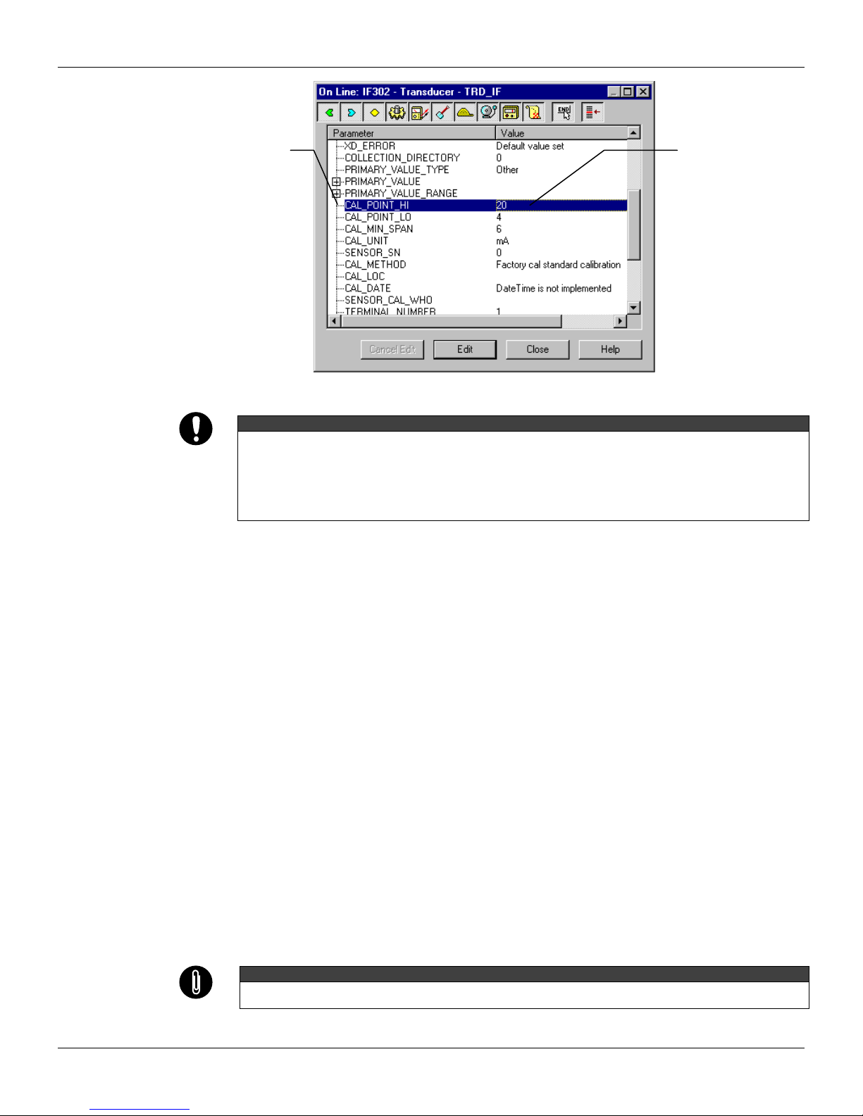
Figure 3.1 - Current Trim - IF302
It is possible to calibrate the current inputs of the transmitter by means of parameters
CAL_POINT_LO and CAL_POINT_HI.
Let’s take the lower value as an example:
Supply 4 mA or the lower value to the terminal block and wait until the readout of parameter
PRIMARY_VALUE stabilizes.
Write 4.00 or the lower value in parameter CAL_POINT_LO. For each value written a calibration is
performed at the desired point.
Figure 3.2 - Current Trim - IF302
Let’s take the upper value as an example:
Supply 20 mA or the upper value to the terminal block and wait until the readout of parameter
PRIMARY_VALUE stabilizes.
Write 20.00 or the upper value in parameter CAL_POINT_HI. For each value written a calibration is
performed at the desired point.
This parameter
selects the
terminal number
which the input
current will be
generated and
calibrated.
In this case the
channel 1 was
chosen.
This parameter
indicates where the
converter should be
when the setpoint
lower value is 0%.
The desired
value should be
entered.
IF302 - Operation and Maintenance Instruction Manual
3.4
Figure 3.3 - Current Trim - IF302
WARNING
It is recommendable that a convenient engineering unit be chosen by means of parameter XD_SCALE of the
Analog Input Block, considering that the range limits of the sensor must be respected, these being 100% and
0%.
It is also recommendable, for every new calibration, to save existing trim data in parameters
CAL_POINT_LO_BACKUP and CAL_POINT_HI_BACKUP, by means of parameter BACKUP_RESTORE,
using option LAST_TRIM_BACKUP.
Via Local Adjustment
The IF302 has 3 input transducers and its device leaves SMAR with factory settings. The factory
setting establishes only the transducers #1 as default for local adjustment. In order to configure the
others via local adjustment, the user should configure them in the display transducer via SYSCON,
according specific instructions for this transducer block.
In order to enter the local adjustment mode, place the magnetic tool in orifice “Z” until flag “MD”
lights up in the display. Remove the magnetic tool from “Z” and place it in orifice “S” until the
message “LOC ADJ” is displayed. The message will be displayed during approximately 5 seconds
after the user removes the magnetic tool from “S”. By placing the magnetic tool the user will be able
to access the local adjustment tree in the monitoring mode.
Browse to parameter P_VAL (PRIMARY_VALUE).
Supply 4.0mA or the lower value to the terminal block and wait until the read of the parameter
stabilizes in the display.
Browse to parameter “LOWER”. After that, in order to start calibration, the user will act on the
parameter “LOWER” by placing the magnetic tool in “S” down to 4.0 mA.
Let’s take the upper value:
Supply 20.0mA or the upper value to the terminal block and wait until the readout of parameter
P_VAL stabilizes, and then actuate parameter UPPER up to 20.0.
Trim mode exits via local adjustment automatically when the magnetic tool is not used during
approximately 16 seconds.
NOTE
Keep in mind that even when parameters LOWER or UPPER present the desired value, they must be actuated
so that calibration is performed.
This parameter
indicates where the
converter should be
when the setpoint is
100%.
The desired value
should be entered.
Table of contents
Other SMAR Media Converter manuals


Popular Media Converter manuals by other brands


Vislink
Vislink UltraDecoder Operator's manual

AJA Video Systems Inc
AJA Video Systems Inc LUT-box Installation and operation guide

SEW-Eurodrive
SEW-Eurodrive MOVITRAC LTP operating instructions

Kramer
Kramer FC-15 user manual

CYP
CYP CLUX-SDI2HCA Operation manual

Lexicon
Lexicon 20 - GUIDE REV 1 Quick reference guide