PRINCIPLES OF OPERATION
SM 5924, Rev. 1, June 2009 2-1
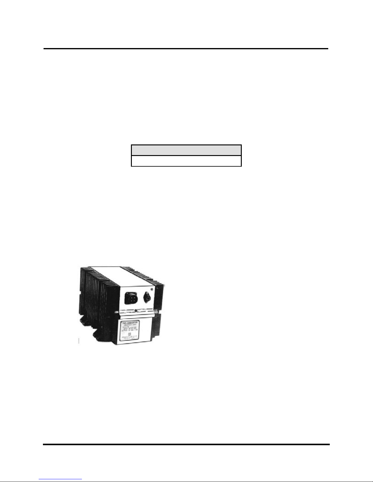
2 PRINCIPLES OF OPERATION
As an aid in understanding the theory of operation, refer to the schematic diagram shown in
Figure 4–1.
2.1 Input Filter
Power is supplied through a filter consisting of inductors L1, and L2, and capacitors C1 and C2.
Reverse polarity and inductive transient protection is provided by diode Dl. This circuitry
removes the steep wave front surges.
2.2 Over Voltage Protection
SCR-1 and circuit board CB3 monitor the input voltage appearing across capacitor C2 and the
pre-regulator voltage across capacitor C3. The circuit is immune to steep wave front surges of
short duration, but will respond to a sustained high voltage of many milliseconds duration.
2.3 Switching Mode Pre-Regulator
The main components of this circuitry are the transistors Q1 and Q2 diode D2, Reactive
Transformer T1, output capacitor C3’ and electronic circuit board CB1. CB1 senses the voltage
across C3 and controls the gate (Q1 and Q2) to regulate the output voltage. CB1 also senses the
current flowing through resistor R5 and current-limits the output by also controlling the gate. A
disconnect is provided through pins 5 and 6 of connector P3 (on CB3) to make the circuit
inoperative if circuit board CB3 is not connected to protect against over voltage. The pre-
regulator can be separated from the output converter by disconnecting connector TP7-1 for test
purposes.
2.4 Power Converter
The power for this circuitry is obtained from the pre-regulated voltage developed across
capacitor C3. The switching bridge transistors Q4, Q5, Q6, and Q7 are controlled by magnetic
oscillator T2 which operates at approximately 400 Hz. The bridge is connected to the load
through an isolating transformer T3. The starting circuit is shown as C°B2 which connects
resistors R5 and R6 to -DC to permit starting with a lamp load. The resistors are automatically
disconnected from -DC when the voltage across capacitor C3 reaches a pre-determined voltage.
Initially capacitor C1 is discharged, therefore, when the voltage across capacitor C3 begins to
rise at turn-on, transistor Q1 turns on, then transistor Q2 follows when the emitter of Q1 reaches
the Zener voltage of D2. This allows the voltage across C3 to reach about half its final voltage
before the converter is permitted to start under full load. Capacitor C1 charges steadily toward
the C3 value and turn off occurs when the base of Q1 is driven negatively to approximately the
Zener voltage of D2. On time is controlled by the values of C1, R1, and R2 and is purposely
made about twice the normal starting time.