SmarAct METIRIO User manual
METIRIO
ENCODER
USER MANUAL

Copyright © 2022 SmarAct Metrology GmbH & Co. KG
Specifications are subject to change without notice. All rights reserved. Reproduction of images,
tables or diagrams prohibited.
The information given in this document has been checked carefully and is updated constantly.
Nevertheless, it is not possible to fully exclude the presence of errors. In order to always get the
latest information, please contact our technical sales team.
SmarAct Metrology GmbH & Co. KG, Rohdenweg 4, D-26135 Oldenburg
Phone: +49 (0) 441 - 800879-0, Telefax: +49 (0) 441 - 800879-21
Internet: www.smaract.com, E-Mail: metrology smaract.com
Document Version: 1.0.1
www.smaract.com | Page 2Metirio Encoder User Manual

TABLE OF CONTENTS
1 Introduction ..................................................................................................................................... 5
1.1 Benefits...................................................................................................................................... 5
1.2 METIRIO Family Overview ....................................................................................................... 5
1.2.1 Readheads and Encoders............................................................................................ 5
1.2.2 METIRIO accessories ................................................................................................... 7
1.3 Preface ....................................................................................................................................... 8
1.4 Technical Support ..................................................................................................................... 9
1.5 Signal Words and Symbols ...................................................................................................... 9
1.5.1 Signal Words.................................................................................................................. 9
1.5.2 Symbols ......................................................................................................................... 10
1.6 Warranty and Liability .............................................................................................................. 10
1.7 Life Support Policy.................................................................................................................... 11
2 Product Safety ................................................................................................................................. 12
2.1 Notes on legal requirements................................................................................................... 12
2.2 Applications and Indended Use.............................................................................................. 13
2.3 Personnel Qualification ........................................................................................................... 14
2.4 General Safety Instructions ..................................................................................................... 14
2.5 Electrical Safety......................................................................................................................... 15
2.6 Handling Precautions............................................................................................................... 15
2.7 Notes on Maintenance............................................................................................................. 18
3 Working Principle............................................................................................................................ 19
3.1 General Working Principle....................................................................................................... 19
3.2 Typical Output Signals.............................................................................................................. 20
4 Technical Data ................................................................................................................................. 22
4.1 Absolute Maximum Ratings .................................................................................................... 22
4.2 Electrical Data ........................................................................................................................... 22
4.2.1 Pin Description METIRIO Readhead .......................................................................... 23
4.2.2 Pin Description METIRIO A1 ...................................................................................... 24
4.2.3 Integrated Circuit Block Diagram................................................................................ 25
4.2.4 Requirements for Subsequent Electronics................................................................ 26
4.2.5 Power-up specification ................................................................................................ 27
4.2.6 Description of adjustable settings.............................................................................. 28
4.2.7 Digital Specification ...................................................................................................... 33
4.3 Environmental Conditions....................................................................................................... 35
4.4 Mechanical Data ....................................................................................................................... 36
4.4.1 Dimensional Outline METIRIO Readhead ................................................................. 36
4.4.2 Dimensional Outline METIRIO A1 ............................................................................. 36
4.4.3 METIRIO Readhead Components .............................................................................. 37
www.smaract.com | Page 3Metirio Encoder User Manual

TABLE OF CONTENTS
4.5 Scale Specifications .................................................................................................................. 38
4.5.1 Linear Scale Specifications .......................................................................................... 40
4.5.2 Rotary Scale Specifications.......................................................................................... 41
4.5.3 Convex Scale Specifications ........................................................................................ 42
4.5.4 Scales with Reference Marks....................................................................................... 43
5 System Integration ......................................................................................................................... 46
5.1 METIRIO Readhead Mounting Examples .............................................................................. 46
5.2 METIRIO Readhead Soldering Precautions........................................................................... 47
5.3 METIRIO Readhead Alignment to Scales............................................................................... 48
5.3.1 Alignment to Linear Scales .......................................................................................... 50
5.3.2 Alignment to Rotary Scales.......................................................................................... 52
5.3.3 Alignment to Goniometer Scales................................................................................ 53
5.3.4 Alignment of METIRIO A1 to Scales ........................................................................... 54
6 Appendix: Order Codes.................................................................................................................. 55
6.1 METIRIO Readheads Order Codes......................................................................................... 55
6.2 Metrology Scales Order Codes................................................................................................ 57
6.3 METIRIO Accessories Order Codes ........................................................................................ 58
7 Appendix: Disposal of Old Equipment ....................................................................................... 60
www.smaract.com | Page 4Metirio Encoder User Manual

1INTRODUCTION
1.1 Benefits
Congratulations on your purchase of the SmarAct METIRIO Encoder. You have acquired a new
and powerful tool for measurements of linear and rotary displacement. The METIRIO is a reflec-
tive optical encoder which is configured to output analog sine and cosine displacement signals.
It can be integrated as OEM component into positioning systems comprising scales to enable a
closed-loop motion control. It is designed to read incremental scales as well as reference marks.
The compact METIRIO readhead is a very small flip-chip package similar to the SON standard with
soldering pads on the bottom side. The METIRIO encoder combines several advantages.
Features
Sub-nanometer resolution,
Most compact encoder of it’s class,
Infrared wavelength (850 nm),
Very low current consumption: 20 mA,
Ultra high vacuum (UHV) compatibility,
Multiple linear, convex and rotary scale options,
Applications
Rotary encoders
Linear encoders
Robots
Linear motors
Precision stages
Galvanometers
1.2 METIRIO Family Overview
This section provides an introduction to the modular METIRIO product family and the variety of
compatible accessories.
1.2.1 Readheads and Encoders
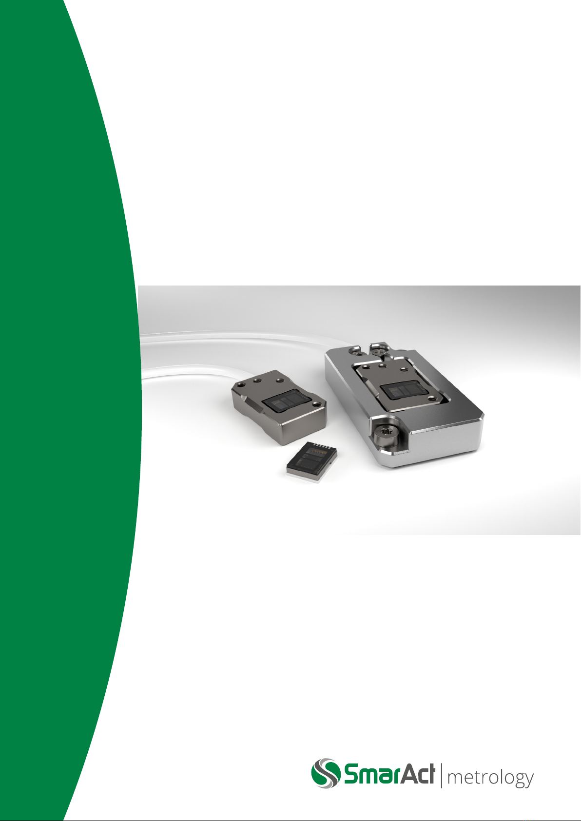
The diagram in figure 1.1 shows the hierarchy of METIRIO encoders. The basic component of any
encoder system is the readhead. Readheads are available in different housing variants. The heart
of every readhead is always the basic OEM component, which is simply called METIRIO Readhead.
It is a flip-chip sensor package. The optical and electrical funcionality is fully integrated in this
readhead. Any further housing variant is based on the METIRIO Readhead. Hence, all technical
specificatoins apart from the external dimensions and the connection pinout are identical for all
variants.
www.smaract.com | Page 5Metirio Encoder User Manual
1 INTRODUCTION
Figure 1.1: Scheme of the METIRIO family encoders
In Particular the following specificaions are identical for the METIRIO Readhead and all other read-
head housing variants:
•Optical Specifications
•Electrical analog and digital specifications
•Alignment Tolerances
The METIRIO A1 comprises an aluminum housing with mounting threads, the integraded ME-
TIRIO Readhead, a cable with strain-relief and a connection plug. The METIRIO A1 can be further
integraded into taylored external housings, to match any mounting requirement.
An encoder consists of a readhead combined with a measuring scale. It is intended that the read-
head is connected to a motion controller which provides the power supply and is capable to inter-
pret and further process the encoder output signals. The readhead outputs analog incremental
and reference signals related to the relative displacement of the scale in the measuring direc-
tion. These signals have to be digitized and further processed by the motion controller in order to
perform closed-loop movement. The motion controller is not part of the METIRIO product family.
Compatible motion control systems are for example the controllers of the SmarAct MCS 2 family.
METIRIO is an analog 1D encoder.
www.smaract.com | Page 6Metirio Encoder User Manual
1 INTRODUCTION
NOTICE
This user manual describes the METIRIO encoder, basically the METIRIO read-
head and the alignment to scales. Where applicable, the deviating specifications
of the METIRIO A1 housing variant are given. Custom made external housings or
available accessories are not described in this user manual.
1.2.2 METIRIO accessories
SmarAct Metrology provides several accessories for the METIRIO encoder, which come with their
own user documentation. Here we just give a brief overview of available accessories and their
intended use.
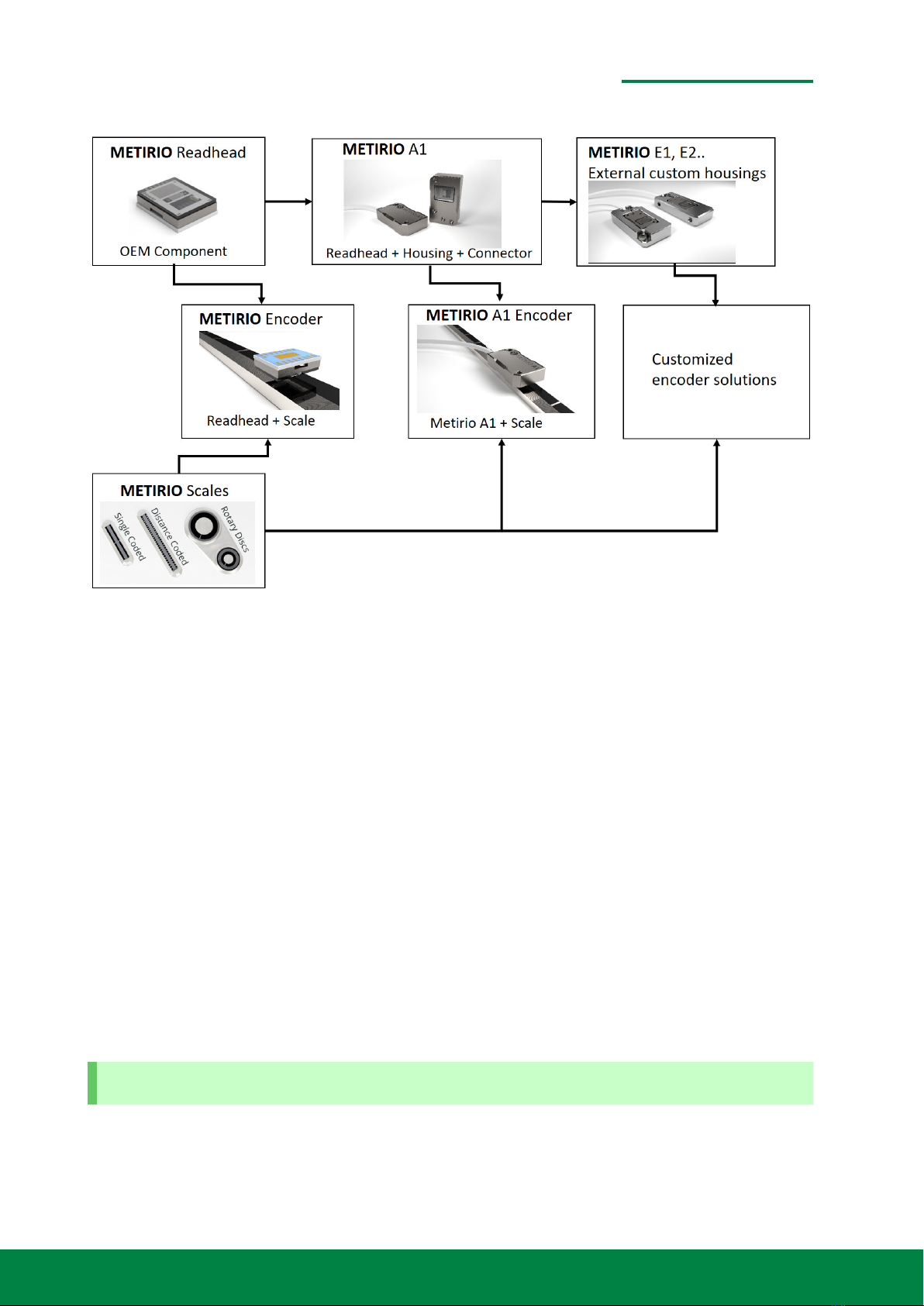
Figure 1.2: ENCODER INTERFACE MODULE
The following accessories are available:
•ENCODER INTERFACE MODULE (IM): This is an electronic interface adaptor to digitize the
analog output signals of the METIRIO Readhead and convert them to standard quadrature
signals, if the customer’s controller is uncapable to interprate the analog signals. The IM can
directly be connected to the METIRIO A1 D-Sub 15 connector.
•ENCODER EVALUATION MODULE (EEM): The EEM is a box that can be connected to the stan-
dard D-Sub 15 plug of the METIRIO A1 on the one side and via USB to a PC on the other side.
It is a tool to quickly interact directly with the I2C interface of the readhead in order to set
the electrical settings and store them to the readhead’s internal memory. This tool does not
replace a motion control system and does not calculate positions from the readhead signals.
The METIRIO can also be addressed directly by any controller that provides the I2C interface,
but utilizing the EEM gives a direct and simple approach.
•ENCODER EVALUATION PROGRAM (EEP): This software is used in combinatin with the EEM
and provides a graphical user interface to communicate with the METIRIO Encoder and vi-
sualize the analog signals for a quick adjustment.
www.smaract.com | Page 7Metirio Encoder User Manual
1 INTRODUCTION
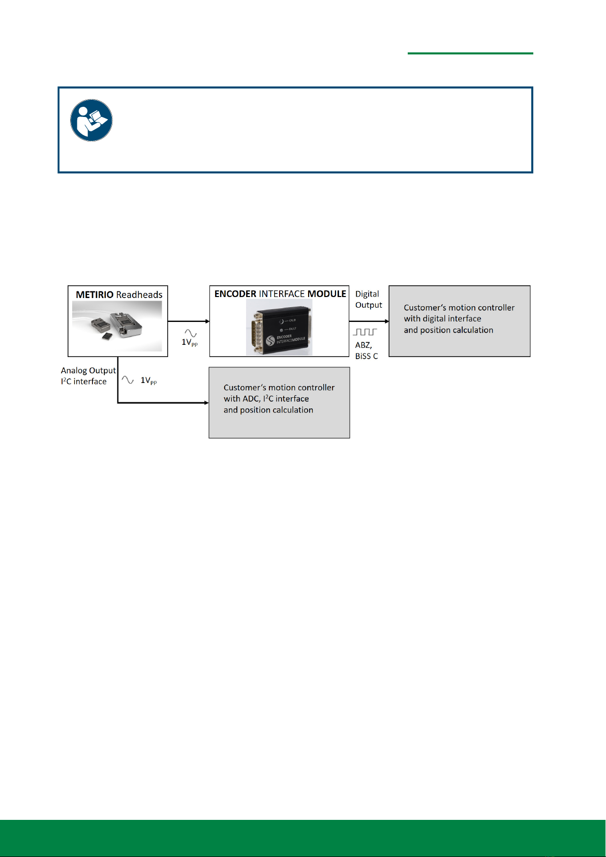
•ENCODER EVALUATION SLIDE (EES): The EES is a mechanical setup comprising a movable
rail system onto which a METIRIO A1 can be mounted and a standard measuring scale. It
is intended to be used to visualize the working principle and the alignment tolerances of a
motion system comprising a METIRIO Encoder. It can be used to quickly attach a METIRIO
A1 for diagnosis since the optomechanical setup corresponds to the standard setup for ME-
TIRIO A1 encoders.
•ENCODER EVALUATION KIT (EEK): The EEK is a complete starter-kit comprising the METIRIO
A1 , the EES, the EEM and the EEP.
Figure 1.3: ENCODER EVALUATION KIT
1.3 Preface
This manual will help you to install and operate the METIRIO Encoder safely in its intended use
scenario. Please read this manual carefully before installing and using any METIRIO product.
This user manual supersedes all previous editions, which thereby become invalid.
NOTICE
Read this manual carefully before operating the METIRIO for the first time.
Special attention should be given to chapter 2 "Product Safety".
Any information provided to you regarding custom modifications to standard products or the com-
bination of standard products takes precedence over the general instructions.
www.smaract.com | Page 8Metirio Encoder User Manual

1 INTRODUCTION
1.4 Technical Support
Should you experience any difficulties with your product or need further technical information,
please visit our web site (https://www.smaract.com/metrology) or feel free to contact our
technical support:
SmarAct Metrology GmbH & Co. KG
Rohdenweg 4
26135 Oldenburg
Germany
+49 (441) 800 879 -0
metrology smaract.com
When communicating with our technical support, you will be asked for the serial numbers, which
can be found on the product.
1.5 Signal Words and Symbols
This manual contains sections in which particular hazards are defined or special attention is drawn
to particular conditions. These sections are indicated with signal words and safety symbols (picto-
rial hazard alerts).
1.5.1 Signal Words
Four signal words are used in this documentation: DANGER,WARNING,CAUTION and NOTICE.
The signal words DANGER,WARNING and CAUTION designate the level of hazard when your own
safety, and/or that of other people, is involved. Do not proceed beyond a signal word until the
indicated risks of personal injury are fully understood and all indicated preventive measures have
been taken.
DANGER
Indicates a hazardous situation that, if not avoided, will result in death or serious injury.
WARNING
Indicates a hazardous situation that, if not avoided, could result in death or serious injury.
CAUTION
Indicates a hazardous situation that, if not avoided, could result in minor or moderate in-
jury.
The signal word NOTICE is used when there is a risk of property damage:
www.smaract.com | Page 9Metirio Encoder User Manual

1 INTRODUCTION
NOTICE
Indicates information considered important, but not hazard-related.
Messages relating to hazards that could result in both personal injury and property damage are
considered as safety messages and not as property damage messages.
1.5.2 Symbols
The signal words DANGER,WARNING and CAUTION always come along with a safety symbol that
indicates a special hazard, regardless of the hazard level:
This symbol is intended to alert the operator of important operating and mainte-
nance instructions. Refer to the manual, if this symbol is depicted on the product.
This symbol is intended to alert the operator to the presence of dangerous optical
radiation that may be of sufficient magnitude to be harmful to the eye.
This symbol is intended to alert the operator to the presence of hot surfaces of
the product that may be of sufficient magnitude to constitute a risk of burning.
1.6 Warranty and Liability
The general terms and conditions of sale and delivery of SmarAct Metrology GmbH & Co. KG
or an equivalent contract negotiated between the contracting parties shall always apply. These
are available upon signing the contract, placing an order or at https://www.smaract.com/
en/imprint. No warranty or liability claims may be made in the event of injury to persons or
damage to property if this has arisen from one or more of the following:
•Failure to comply with the information in the operating instructions regarding safety, trans-
port, storage, installation, operation and maintenance of the device.
•Improper use of the product.
•Incorrect assembly and operation.
•Operation of damaged or defective devices.
www.smaract.com | Page 10Metirio Encoder User Manual

1 INTRODUCTION
•Operation with defective or deactivated safety and protective features or devices.
•Unauthorized repairs or unauthorized modifications to the device.
•Inadequate monitoring of parts which are subject to wear.
•Damage caused by exposure to water or other substances, e.g. condensation water forma-
tion.
•Damage caused by the intrusion of foreign objects.
1.7 Life Support Policy
DANGER
SmarAct Metrology GmbH & Co. KG does not authorize or warrant any of its prod-
ucts for use in life support systems, without the specific written consent of Smar-
Act Metrology GmbH & Co. KG.
Life support systems are equipment intended to support or sustain life, and whose failure to per-
form, when properly used in accordance with instructions provided, can be reasonably expected
to result in personal injury or death.
www.smaract.com | Page 11Metirio Encoder User Manual

2PRODUCT SAFETY
Please read the following information, warnings and safety instructions in this section carefully
before using the product.
2.1 Notes on legal requirements
Declaration of
Conformity
according to DIN EN ISO/IEC 17050-1:2010
Manufacturer: SmarAct Metrology GmbH & Co. KG
Manufacturer’s Address: Rohdenweg 4
26135 Oldenburg, Germany
The manufacturer hereby declares that the METIRIO encoders comply with the following
European directives:
2014/35/EU: Low Voltage Directive
2011/65/EU: RoHS Directive, including ammendemends
METIRIO encoders fulfill the requirements of standards listed below:
DIN EN 62471:2009-03 Photobiological safety of lamps and lamp systems. The integrated
light source is classified to be RG-0 (free group), only if the supply
current is limited to 1000 mA.
DIN EN IEC 63000:2019-05 Technical documentation for the assessment of electrical and
electronic products with respect to the restriction of hazardous
substances
DIN EN 61010-1:2020-03 METIRIO encoders fulfill the requirements of DIN EN 601010-
1:2020-03 only, if the power supplied by the secondary circuit is
of PELV or SELV type.
METIRIO encoders fulfill the requirements of only, if the energy is
limited to safe values. Other applicable standards may be consid-
ered.
EN 61326-1:2013 Integrated circuits - Measurement of electromagnetic emissions -
Part 1: General conditions and definitions. Emission Class B.
www.smaract.com | Page 12Metirio Encoder User Manual

2 PRODUCT SAFETY
Articles manufactured on or after the Date of Issue of the Declaration of Conformity do not con-
tain any of the restricted substances in concentrations/applications not permitted by the RoHS
Directive.
This user manual supersedes all previous editions.
August 31, 2022
Oldenburg, Germany Dr. Sebastian Rode
CEO
2.2 Applications and Indended Use
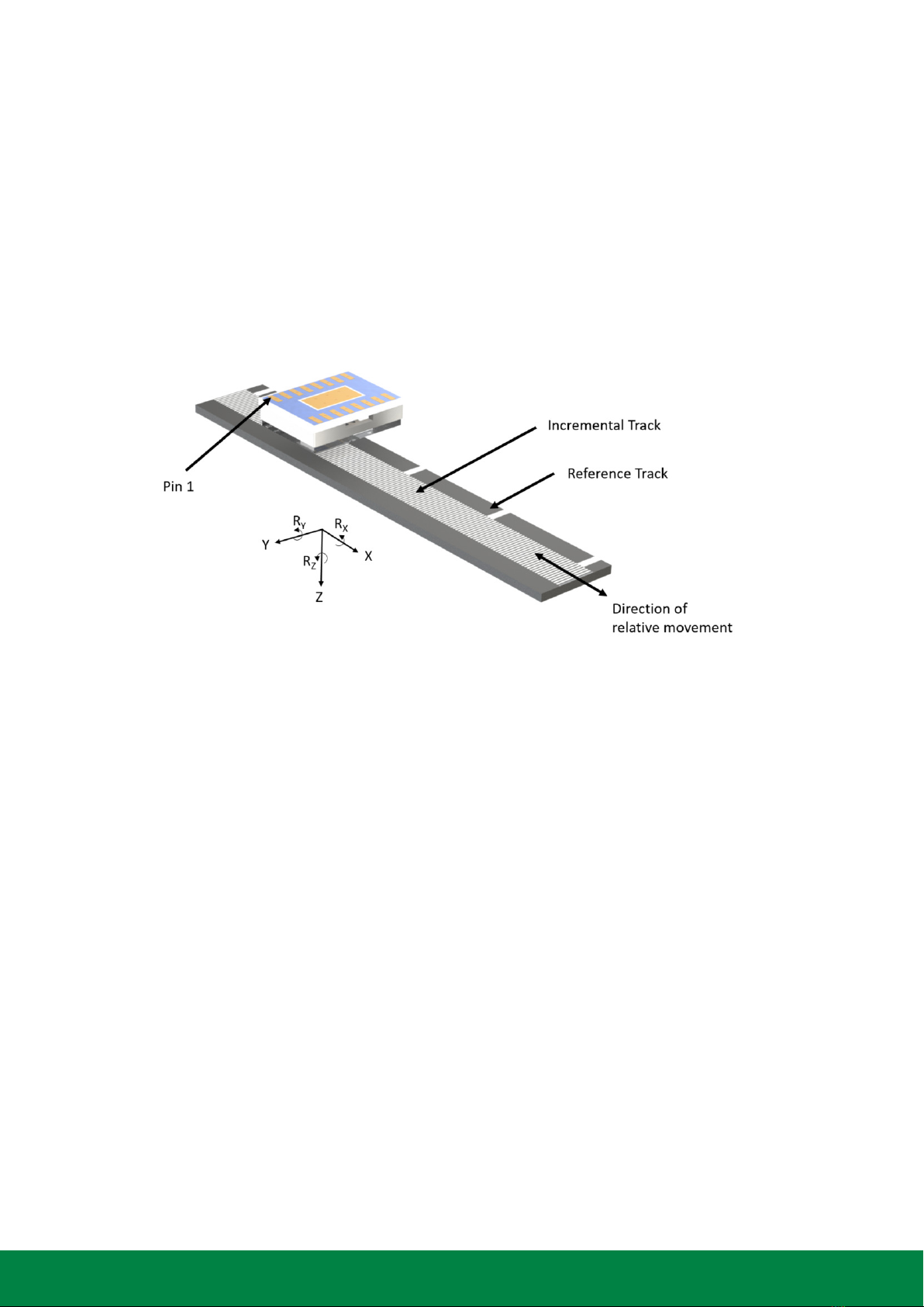
Figure 2.1: Typical measurement setup
The METIRIO Readhead is designed to read scales with an incremental pitch of 20 µm and refer-
ence marks. The read head is an OEM product that can be integrated into or mounted on any kind
of machinery with movable axes to detecte the relative movement to the scale. Users are free to
choose both the mounting on the movable or the fixed parts of any rail stages, rotary stages or
goniometers. Industrial and research environments are the intended use fields. Any utilization in
end consumer products is subject to the responsibility of the OEM integrator.
Encoders of the METIRIO series are suitable for manifold applications. The following list is not a
limitation, but can be understood as application examples.
•Production machines
•Turning machines
•High Precision coordinate measuring meachines
www.smaract.com | Page 13Metirio Encoder User Manual

2 PRODUCT SAFETY
•Semiconductor inspection and production sites
•Robotics
•Microscopy stages
•Laboratory positioning devices
For further notice about the environmental conditions refer to the technical data in section 4.3
2.3 Personnel Qualification
The customer as OEM system integrator has to ensure that persons are trained and able to fully
assess the safety and conformity of the machine or equipment into which SmarAct components
are incorporated in accordance with local laws and regulations. In particular to positioners and
motion systems the national implementations of the Machinery Directive 2006/42/EC apply.
2.4 General Safety Instructions
To ensure reliable and safe operation of the device please pay attention to the safety instructions.
NOTICE
Since the METIRIOis an OEM component, SmarAct does not guarantee functional
safety according to ISO 13849, IEC 61508 or any other applicable standards. The
system integrator is advised to the following notices for reliable position signals.
In order to continuously maintain reliable position signals, especially during closed loop position-
ing or any other critical operation, the following notices are advised:
•Do not interrupt the power supply to the sensor.
•Do not utilize the power down capabilities of the METIRIOwhile the axis is moving, since the
position information will be lost for a short period of time, depending on the applied duty
cycle.
•Do not change gains, offsets or any other settings during critical operation. Any adjustment
action will change the sine or cosine position signals. This will lead to a change in the here-
from calculated position, even if the physical position did not change.
•Do not use I2C-communication with the device, i.e. do not write or read registers during
critical operation. This may cause influence to the position signals, especially when operating
at high bandwidth, i.e. at high movement speed.
•Monitor the position signals and implement an emergency stop to the machine control sys-
tem in case the signal leave the predefined margins.
•Ensure that the operating conditions and mounting tolerances with respect to the scale are
maintained during operation.
www.smaract.com | Page 14Metirio Encoder User Manual

2 PRODUCT SAFETY
•The accuracies listed in the specifications and the operation reliability depend on the toler-
ances in the mounting instructions. Ensure that the machine tolerances do not exceed this
tolerances.
DANGER
When the METIRIO is used for closed loop movement of any machine part, the
machine can move in an uncontrolled manner and cause injuries, in case the posi-
tion signals are lost or modified during operation, in particular if the above notices
are ignored.
2.5 Electrical Safety
Before connecting and operating any METIRIO product, please ensure the following:
•Comply with the applicable PIN assignment.
•The Power supplied by the secondary electronics should be of PELF or SELV type.
•The energy provided by secondary electronics should be limited to safe values according to
DIN EN 61010-1:2020-03 or other applicable standards.
NOTICE
ESD (electrostatic discharge) sensitive device.
Charged devices and circuit boards can discharge without detection. Although this
product features proprietary protection circuitry, damage may occur on devices
subjected to high energy ESD. Therefore, proper ESD precaution should be taken
to avoid performance or loss of functionality.
2.6 Handling Precautions
The METIRIO Readhead flip chip package is a sensitive optoelectronic device that needs to be
handeled with care. Please follow the following advices.
WARNING
Handle with care. The METIRIO is a small high precision instrument and subject to
damage under rough handling. A broken device can have sharp edges and cause
cutting injuries.
www.smaract.com | Page 15Metirio Encoder User Manual

2 PRODUCT SAFETY
Figure 2.2: Suitable surfaces for handling
WARNING
In an error case it might be possible, that the LED current exceeds 1000 mA. In this
case, optical radiation above the maximum exposure limits for infrared radiation
can be emitted by the device for a short time.
CAUTION
Due to a lack of heat dissipation when operating in vacuum the user should ensure
apprppriate mounting to heat sinks.
CAUTION
Do not operate the METIRIO encoder under water. This will lead to short circuit
of the device. Operation in distilled water or other non-conductive liquids will
also cause the device to be optically inoperable due to the refractive index of the
environment.
NOTICE
Take care not to wedge the readhead during installation. Under no circumstances should
wedging or levering forces be used to grab or mount the readhead. Make sure that the read
head is not jammed when adhesive cures, especially if thermal curing adhesives are used
for mounting.
www.smaract.com | Page 16Metirio Encoder User Manual

2 PRODUCT SAFETY
NOTICE
Avoid sealing the venting slots particularly when using fluid adhesives for mounting and op-
eration in vacuum. Otherwise the readhead could be an artificial leeak due to overpressure
inside.
Take further care when mounting and handling the readhead:
•Do not scratch the cover glass surface of the readhead.
•Do not scratch the surface of the scale.
•Do not expose the device to very bright light for example flash light or direct sunlight.
•Use gloves or plastic tweezers to touch the device in order to protect the device from con-
tamination.
•Do not use metal tweezers.
•In order to avoid malfunction, do not cover the optically active area of the cover glass when
mounted.
•Do not apply pull, shear or compressive forces above 1000 cN (1 kg) to any surface of the
readhead.
•Operation in liquid or gaseous environments with refractive index other than vacuum or nor-
mal air, will not work or lead to reduced signal quality and inaccurate measurement results.
Figure 2.3: Gripping and mounting precaution
www.smaract.com | Page 17Metirio Encoder User Manual

2 PRODUCT SAFETY
NOTICE
When gripping the read head, make sure that the contact surface on the side frame is flat.
Do not reach into the openings. Componentes inside the package can be damaged.
2.7 Notes on Maintenance
•The METIRIO encoder devices do not requiere maintenance. However cleaning of the sur-
faces in case of contamination could be advised in order to achieve optimal signal quality.
•Clean the glass surface of the readhead or the scale with care. Use proper tissues in order
to not scratch while cleaning.
•In order to maintain UHV capability do not use Acetone or any other chemicals in the last
cleaning step, except from the ones listed below:
–N-heptane: CH3(CH2)5CH3
–Propan-2-ol: CH3CHOHCH3
•Any contamination of the scale can lead to signal distortions and loss of signal quality and
may result in measuring errors. Hence cleaning of the scale from time to time or in case of
visible contaminations is advised.
www.smaract.com | Page 18Metirio Encoder User Manual
3WORKING PRINCIPLE
3.1 General Working Principle
Figure 3.1: Typical measurement setup
Without going too deep into detail, in this chapter the basic working principle is described. For
further information on functionality and system integration, refer to chapters 4 and 5.
A reflective scale and the readhead are mounted to the opposite moving parts of a motion system,
so that either the scale or the readhead can move relative to the other part in one direction. The
readhead needs to be properly aligned with respect to the scale. Once the readhead is connected
to the power supply, the integrated ASIC will start up with the predefined settings in the memory.
The settings define the operating point, for example the brightness of the light source and the
gains of the photoiode amplifiers. These settings can be changed and stored to the memory via
the chip’s digital interface.
With proper settings, the light source illuminates the scale, which will reflect the light back and
in combination with the grating optics of the readhead will generate a special light pattern. The
distribution of the light pattern will change depending on the relative displacement between the
scale and the readhead. The photodiode arrays of the readhead will detect this light pattern,
and convert it into photo currents. The ASIC converts these photo currents into amplified output
voltages with 1 V peak to peak amplitude.
Additionally to the periodical incremental track, the scale can comprise a second track with refer-
ence marks. These marks will also reflect light to another light detecting array within the readhead.
The ASIC generates a TTL-shaped reference signal at each detected reference mark.
www.smaract.com | Page 19Metirio Encoder User Manual
3 WORKING PRINCIPLE
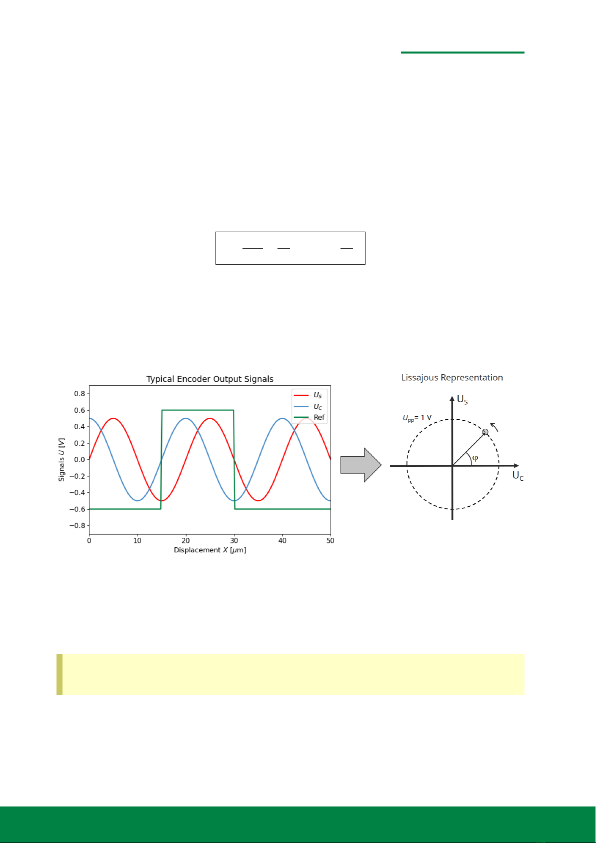
3.2 Typical Output Signals
When plotted against the displacement, the signals will have a sinusoidal shape and vary periodi-
cally, if the displacement extends over several periods of the scale. The period corresponds to the
scale pitch of 20 µm. METIRIO will output two incremental signals which are phase shifted by π/2.
These two incremental analog signals, can be analyzed by the motion controller. For example in a
Lissajous representation, the two signals will form a circle in case of an ideal optical and electrical
alignment. From the actual phase the actual incremental displacement can be directly calculated
by the controller according to the equation:
XP=P·ϕ
2π=P
2π·arctan US
UC(3.1)
where Pis the pitch of the scale, which is always 20 µm for METIRIO encoders. The position XPwill
vary periodically between 0 and 20 µm. In order to obtain a continuous position, the controller
needs to count and increment the integer period count number neach time, the phase crosses
zero. Finally the displacement is:
X=n·P+XP. (3.2)
We are used to looking at electrical signals as a function of time, for example when they are
Figure 3.2: Illustration of the output signals of a METIRIO Encoder and their lissajous representa-
tion for perfect optical alignment and proper gain-settings.
displayed with an oscilloscope. However, the signals in figure 3.2 are shown as a function of the
relative displacement between the readhead and the scale. A sinusoidal shape as a function of
time will only be observed for a constant movement speed.
When displayed as a function of time, the encoder signals can have any shape. If no move-
ment occurs, they can even be DC-signals.
Each time the encoder passes a reference mark, a square wave signal is generated. The width and
position of this signal can be adjusted via the I2C interface. The reference mark width should be
a bit less than one period Pand the position should be centered to the upper crosspoint of the
www.smaract.com | Page 20Metirio Encoder User Manual
Table of contents
Popular Media Converter manuals by other brands


Syscom Video
Syscom Video 8CH FX-TRON instruction manual

Transition Networks
Transition Networks M/GE-SW-SFP-01-U Series user guide

Manhattan
Manhattan 151443 instructions

IMC
IMC mcbasic 10/100 installation guide

Elo TouchSystems
Elo TouchSystems E06G Operation manual

AEG
AEG ST 800 Operation and safety notes