smart acoustic SWM260 User manual

OPERATION MANUAL
SWM260 / SWM360
WIRELESS MICROPHONE SYSTEMS
SWM360
WIRELESS MICROPHONE SYSTEM
SWM260
WIRELESS MICROPHONE SYSTEM

Contents
System Components 3
SWM260 Receiver Functions 4
SWM360 Receiver Functions 5
Receiver Display Functions 6
Receiver Set Up 7
SHM260 Handheld Transmitter 8
SBP260 Bodypack Transmitter 10
Channel Sync ASC Function 12
Installation Racks 13
Important Safety Instructions 14
Troubleshooting 15
Speci cations 16
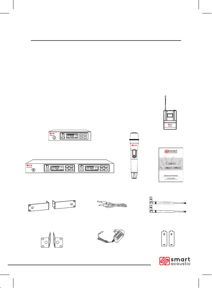
System Components
SWM260 SYSTEM
•SWM260 Receiver
•SHM260 Handheld Transmitter OR
•SBP260 Bodypack Transmitter
•Headset (SWM260BP model only)
• Lapel Mic (SWM260BP model only)
•1/4 Audio Cable
•Power Adapter
•Rack Panel x 2
•Antenna x 2
•Battery x 2
•User Guide
SWM260
WIRELESSMICROPHONESYSTEM
SWM360
WIRELESSMICROPHONE SYSTEM
SBP260
BODYPACKTRANSMITTER
SHM260
SWM260
WIRELESSMICROPHONESYSTEM
SWM360
WIRELESSMICROPHONE SYSTEM
SBP260
BODYPACKTRANSMITTER
SHM260
SWM260
WIRELESSMICROPHONESYSTEM
SWM360
WIRELESSMICROPHONE SYSTEM
SBP260
BODYPACKTRANSMITTER
SHM260
SWM260
Receiver
SWM360
Receiver
SHM260
Handheld
Transmitter
1/4 AUDIO CABLE
ANTENNA
BATTERY (x2 or x4)
POWER ADAPTER
SWM360
Rack Panel
SWM260
Rack Panel
USER GUIDE
SWM360 SYSTEM
•SWM360 Receiver
•SHM260 Handheld Transmitter
•SBP260 Bodypack Transmitter
•Headset
•Lapel Mic
•1/4 Audio Cable
•Power Adapter
•Rack Panel x 2
•Antenna x 2
•Battery x 4
•User Guide
Page. 3
SWM260
WIRELESSMICROPHONE SYSTEM
SWM260
WIRELESSMICROPHONESYSTEM
SWM360
WIRELESSMICROPHONE SYSTEM
SBP260
BODYPACKTRANSMITTER
SHM260
SBP260
Bodypack
Transmitter

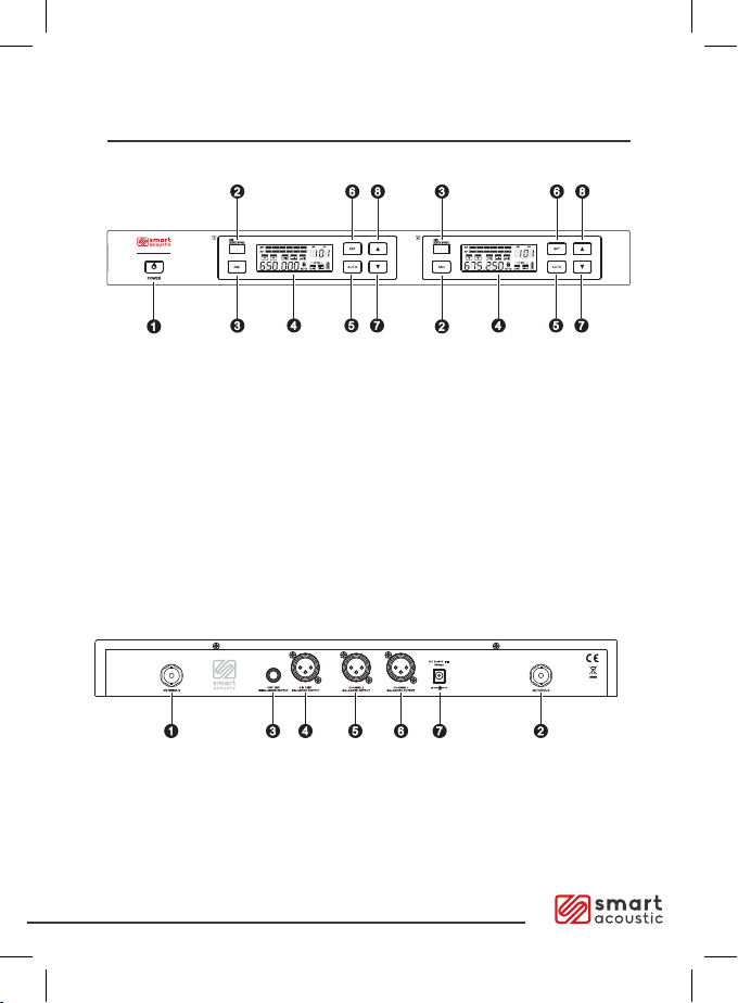
SWM260 Receiver Functions
SWM260
WIRELESS MICROPHONE SYSTEM
SWM360
WIRELESSMICROPHONE SYSTEM
1. Power switch
2. Infrared frequency “IR” window
3. ASC button for infrared frequency sync; Press this key, the screen IR
will ash for approximately 10 seconds in the microphone IR window
4. LCD display
5. AUTO menu button, for fast frequency sweep
6. SET button, to set up all the functions shown on the LED screen
7. 8. UP and DOWN buttons for fast channel setting
1. DC power socket
2. XLR output socket
3. 1/4” output socket
4. Antenna jack B
5. Antenna jack A
SWM260 Receiver Rear Connections
Page. 4
SWM360 Receiver Functions
SWM260
WIRELESS MICROPHONE SYSTEM
SWM360
WIRELESSMICROPHONE SYSTEM
1. Antenna jack B
2. Antenna jack A
3. 1/4” Mix output socket
4. XLR Mix output socket
5. Channel 2 x LR output socket
6. Channel 1 x LR output socket
7. DC power adapter socket
Page. 5
SWM360 Receiver Rear Connections
1. Power switch
2. Infrared frequency “IR” window
3. ASC button for infrared frequency sync; Press this key, the screen IR
will ash for approximately 10 seconds in the microphone IR window
4. LCD display
5. AUTO menu button, for fast frequency sweep
6. SET button, to set up all the functions shown on the LED screen
7. 8. UP and DOWN buttons for fast channel setting
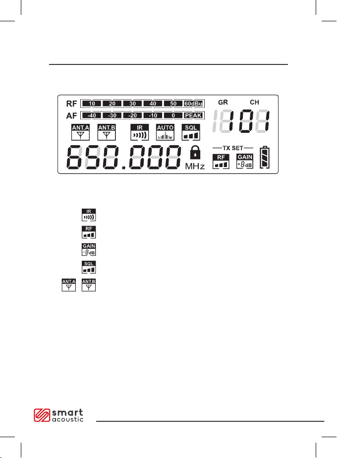
Receiver Display Functions
ASC sync indicator
Transmitter power RF
Transmitter microphone gain adjustment level
Noise gate threshold
Receiver RF Antenna
Current group
Current channel
Receiver signal strength
Audio Level
GR
CH
RF
AF
Page. 6

Receiver Set Up Page. 7
Frequency number and channel selection:
Press “SET” button for two seconds to unlock “ ” and press the “SET”,
“GR” ashing, press or to select the appropriate channel, as shown
in Figure ;
Then press “SET”, “CH” ashing, press or to select the appropriate
channel, such as shown in Figure ;
Then click “SET”, “SQL” ashing, press or to select an SQL
squelch start end, three stall regulation , such as shown in Figure ;
Then click “SET”, “TX SET” and RF ashing, press or to
select a transmit power adjustment, as shown in gure ;
Then click “SET”, “TX SET” and GAIN ashing, press or to
select the microphone gain adjustment is shown in Figure ;
Receiver volume control:
This device has an electronic volume control system, according to
the “SET” key “, two seconds ” ” release, press or key control
receiver. The output volume (total 63) as shown in Figure .
1.
2 .
3 .
4 .
5 .
6 .
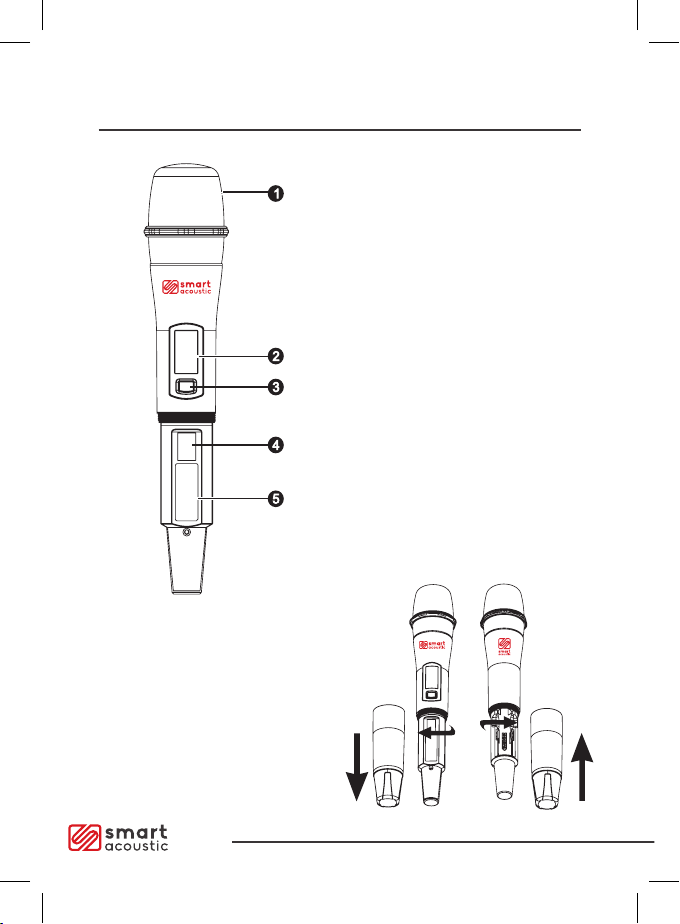
SHM260 Handheld Transmitter
FUNCTIONS
1. Microphone capsule and grill
2. LCD (liquid crystal) display
3. Power Switch; Press and hold for
2 seconds to switch ON or OFF.
Press once to activate or disable
the MUTE function.
4. Infrared frequency (IR) port
5. Battery cover
SHM260
SHM260
SHM260
SHM260
CHANGING BATTERIES
Two alkaline batteries are expected
to last approx. 6 hours run time.
When the display power indicator
is ashing, the battery should be
replaced immediately.
Page. 8
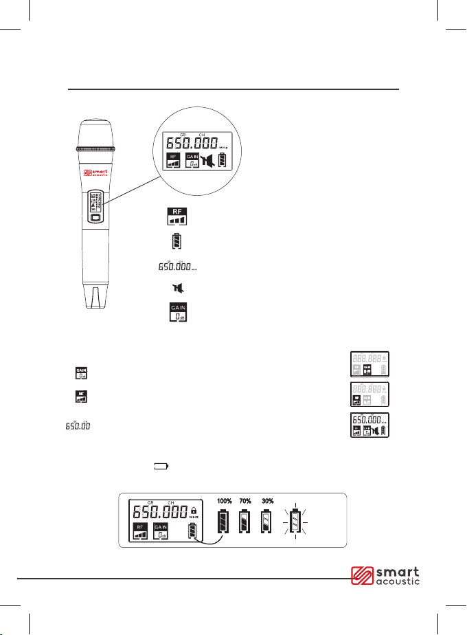
Transmitter Display Function
MUTE: Press Power Switch
once to activate MUTE
function. Mute symbol is
displayed on screen.
Press Power Switch again
to disable MUTE function.
Mute symbol will disappear
from screen.
SHM260
SHM260
SHM260
SHM260
SHM260
Transmitter intensity power display
Battery power display
Frequency of use
Mute symbol
Microphone gain value
SHM260
SHM260
SHM260
SHM260
Microphone gain adjustment displays gain number
Transmit power adjustment displays power number
Frequency of use conrmation displays frequency
Low power tips: When the battery power is less than 1.8V, an
icon appears 3 seconds later, the microphone switches o
automatically. Replace batteries when power indicator is 30% or less
SHM260
Page. 9
SHM260
SHM260
Functions of the Transmitter

SBP260 Bodypack Transmitter
FUNCTIONS
1. Antenna
2. Power Indicator Light
3. LCD Screen
4. Infrared frequency (IR) Window;
Receives the infrared signal,
the frequency synchronisation
5. Press the "SET" switch, set by the
LCD screen
6. "UP" switch, press the "SET"
switch, value is set by the liquid
crystal screen display function
7. / MUTE switch; press and hold
to turn ON or OFF. Press and
release to MUTE or UNMUTE
8. 3-pin mini XLR microphone input
WEARING THE BODYPACK
TRANSMITTER
The Bodypack Transmitter can be
clamped onto a belt Aor can also
be attached to a guitar strap B.
The transmitter should be tightly
secured at all times via the
transmitter clip.
CHANGING BATTERIES
Two alkaline batteries are
expected to last approx. 6 hours.
When the battery low power
indicator is ashing, the batteries
should be replaced immediately.
A
B
A
B
A
B
Page. 10
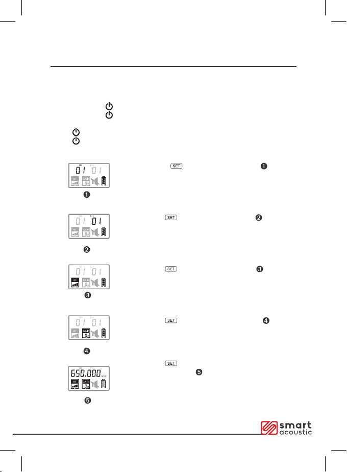
SBP260 Bodypack Transmitter Setting
Manually selecting a frequency or channel:
Long press button to display "GR" .
Press "UP" to change the frequency number
of the group.
Press the button to display "CH" . Press
"UP" to change the frequency of the channel.
Press the button, to display "RF" . Press
"UP" to adjust the transmitter power RF.
Press the button to display "GAIN" . Press
"UP" to adjust the transmitter microphone gain.
Press the button to display the
current frequency.
Page. 11
TRANSMITTER DISPLAY
Power & Mute Activation:
Press and hold MUTE button to Power ON.
Press and hold MUTE button to Power OF.F
Click MUTE to activate MUTE.
Click MUTE again to cancel the mute function.
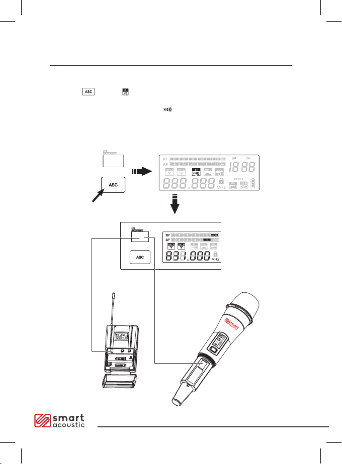
Channel Sync via ASC Function
SHM260
Frequency setting:
Press the button; will ash on the receiver screen. Hold the
transmitter infrared window at the receiver infrared window. Automatic
frequency Sync will be completed. disappears automatically.
If the ASC Sync does not connect on the rst attempt, please repeat sync
steps or try an alternate channel.
Page. 12

Single Receiver Unit Rack Installation
General rooms or close proximity can utilise the 1/4" connection function.
For long distance connections, we suggest using a balanced XLR output
function.
SWM260
WIRELESSMICROPHONE SYSTEM
Page. 13
Rack Panel Ears
1/4" Audio Cable XLR Output
connecting cable
Power Adaptor

Important Safety Instructions
•Please keep transmitter in direct line with the antenna, without any obstacles
between them.
•Please do not put the receiver near any metal surface or digital devices
(such as mobile phone, computer, etc.)
•The receiver should be positioned at least 1 meter o the ground. Please try not
to put it near walls. To ensure enough ventilation, the space between receiver
and other objects should be at least 20cm.
•Do not cover ventilation holes with objects such as paper, or fabrics.
•Transmitting devices such as mobile phones and two-way wireless equipment may
interfere with audio signals. Therefore, the transmitter and receivers should be kept
away from such equipment or any other potential interfering sources.
•Please keep equipment away from all liquids.
•The equipment should only be opened, serviced and repaired by authorised
personnel.
•Keep away from naked ame.
•Do not expose Batteries to environments of excessive heat. Please do not dispose
of batteries in the garbage. Put them in designated recycling bins instead.
•Ensure that power supply connections are in good working condition.
•Working temperature range should be within -10·c to +50·c.
Page. 14

Troubleshooting
Problem Indicator
(lamp) state
Solution
No sound or
faint sound
Transmitter
power light o.
Turn on the main power, conrm the +/ -
mark on the battery and the transmitter
terminal of the phase matching.
Receiver power
indicator o.
Conrm that the AC power adapter is
plugged into a power jack and the other
end is inserted into the receiver. Backboard
straight direct input jack; conrm the AC
power supply is normal, and conrm the
power supply voltage is normal.
Receiver RF
indicator
glows.
Adjustable high receiver volume control;
adjustable high transmitter gain switch
setting; Check the receiver and amplier or
mixer cable connections.
Receiver power
indicator
o. Receiver
RF indicator
glows.
Ensure the receiver is away from metal
objects. Check that there are no obstacles
between the transmitter and the receiver.
Check whether the receiver and transmitter
are using the same frequency.
Transmitter
low-voltage
indicator lights
The Transmitter battery needs replacement.
Distortion or excess
noise
Receiver for RF
signal lights
Remove radio frequency interface from
nearby devices (such as CD, computer,
digital devices, earplugs monitoring system);
transmitter battery replacement; if using
multiple systems, increase the frequency
interval between various systems.
Distortion level
gradually increased
Low Battery
indicator
glows.
Transmitter battery replacement.
Sound level of electric
guitar or microphone,
or use a dierent guitar
sound dierent level
Adjust the transmitter and receiver
volume or gain settings.
Page. 15

Specications
SYSTEM
Frequency Range:
655-679 MHZ - V1 OR
520-542 MHZ - V2
Note: To identify your applicable frequency
band, based on your location within
Australia, please refer to:
https://channelnder.acma.gov.au/
The Transmitter RF Level
13dBm
Typical Work Range
80meters (240feet)
Note: The actual scope and RF signal relate
to absorption, reection and interference
Audio Frequency Response (+/-3dB)
60Hz~15KHz
THD (Total Harmonic Distortion)
(+/- 30khz excursion, 1 khz audio): <1%
Dynamic Range
>100dB (A weighted)
Working Range
-1 0"C to +50"C
Note: Battery characteristics may eect
the scope of the limits.
SHM260 HANDHELD
TRANSMITTER
Maximum audio input level 0dBV
Size 250mm *50mm diameter
(including a microphone head)
Weight 360g (without battery)
Power Required Two 1.5V "AA" batteries
Battery Life >6 hours (approximate)
SBP260 BODYPACK
TRANSMITTER
Maximum audio input level 6dBV
Size 65mm *165mm *22mm
Weight 130g (without battery)
Power Required Two 1.5V "AA" batteries
Battery Life >6 hours (approximate)
RECEIVER
Maximum Audio Output Level
XLR adaptor (switch in 600Ω): >1 0dBV
1/4" adaptor (switch in 3000Ω): >6dBV
Output Impedance
XLR adaptor: 200Ω
1/4" adaptor : 1kΩ
XLR Output
Balance impedance
Contact pin 1: GND
Contact pin 2: (+)
Contact pin 3: (-)
Sensitivity (intermediate frequency
demodulator output SNR 30dB)
<-95dBm
Image Rejection
>70dB
Size
44mm* 212mm* 160mm (SWM260)
44mm* 410mm* 160mm (SWM360)
Weight
880g (SWM260) 1750g (SWM360)
Power Requirements
12V DC, switching power supply 500
milliamperes from external mains power.
This manual suits for next models
1
Table of contents


