Smart Dog SD-2100 User manual

Smart Dog
®
In-ground
Pet Fencing
System
SD-2100, SD-2200
Operation Guide
Thank you for purchasing the Smart Dog In-ground Pet
FencingSystem.
This electronic dog containment system is among the
safest, most humane and effective training products you
can buy. Once your dog is properly trained, he will enjoy
hours of freedom within his new boundaries, and you will
enjoy the comfort of knowing that he has learned to stay
safely in youryard.
Please take a few minutes to read the instruction manual
priortoyourfirst use andretain themanualforfuture refer-
ence. This instructionmanualcontainsimportantprogram-
ming and set-up information to help your training proceed
as successfully as possible. For best results, follow these
important rules:
IMPORTANT SAFEGUARDS
1. Obey all warnings contained in this manual.
2. The electronic dog collar is intended only for use on dogs.
Never attempt to use this product for any purpose not specifi-
cally described in this manual.
3. If you have any reason to believe that your dog may pose a
danger to others, or that it may harm itself if it is not kept from
crossing the boundary wire, you should not rely solely on this
product to contain your dog.
4.Do not leavethecollar onyour dogformorethan12hoursper
day.
5. Never perform set-up procedures when the collar is on your
dog.
6. Never call or pull your dog into the containment field.
7. Keep all system components out of the reach of children.
8. The containment system will not contain your dog unless:
A.Youtrainyour petasprescribedinthetrainingplan(Section
7, pg.15).
B.The transmitter is on, connected to the boundary loop wire,
and producing a signal along the boundary wire.
C.The collar receiver is worn properly by your dog.
D.Thecollar receiverisadjusted sothatthe probesare touch-
ing your dog's skin.
E.There is an adequate charge on the collar receiver battery.
Do not use if you suspect the charge is low.
F. The 24-volt adapter is plugged into the transmitter and is
connected to a 110-volt household outlet.
9. The following precautions should always be taken:
A. Never service or install a system or any equipment during
a thunder or electrical storm.
B. Never install the transmitter where it could be exposed to
the elements, doing so will void the manufacturer's warranty.
C. Monitor the transmitter periodically to ensure that the unit
is operating properly and is producing a signal along the
boundary wire.
D. Always remove your dog's collar receiver before making
any adjustments to your containment system.
E. Use the lowest stimulation necessary to get the desired
behavior.
F. Allow your dog to get used to the collar before you begin
training. You want your dog to accept the collar as part of a
routine, not to associate the collar with the stimulation.
10. To prevent the elimination of an adequate safe zone in your
yard, any adjustments to the field width must be tested prior to
using the system with your dog.Once the field width has been
set and tested, turning the knob in a clockwise direction will
increase the stimulation zone and may eliminate the safe zone,
thus causing stimulation to be present throughout your entire
yard.
11. Read all instructions before using this product. If you have
anyquestionsor concerns after readingthisinformation, contact
Innotek.
IMPORTANT
Realize that because individual dogs have unique tempera-
ments, there is no way of knowing how your dog will react to its
introduction to this product. For the safety of your dog, initial
training should take place using a six foot or retractable leash to
keep you in control of the situation. Also realize that an aggres-
sive animal could turn against the handler upon receiving the
stimulation. Therefore, if you feel your dog has an aggressive
temperament and/or he has a history of aggressive behavior,
you should consult a certified animal behaviorist before using
this product.
1.
IMPORTANT NOTICE: This equipment has been tested and found to comply with
the limits for a Class B digital device, pursuant to Part 15 of the FCC Rules. These
limitsare designed toprovide reasonable protection againstharmful interference in
a residential installation.This equipment generates, uses and can radiate radio fre-
quency energy and, if not installed and used in accordance with the instructions,
may cause harmful interference to radio communications. However, there is no
guarantee that interference will not occur in a particular installation. If this equip-
ment does cause harmful interference to radio or television reception, which can
be determined by turning the equipment off and on, the user is encouraged to try
to correct the interference by one or more of the following measures:
• Reorient or relocate the receiving antenna.
• Increase the separation between the equipment and receiver.
• Connect the equipment into an outlet on a circuit different from that to which the
receiver is connected.
• Consult the dealer or an experienced radio/TV technician for help.
Caution:Changes or modifications to any component, not expressly approved by
Innotek, Inc., could void the user's authority to operate this equipment.
The term "IC:" before the radio certification number only signifies that Industry of
Canada technical specifications were met.
Innotek,Inc.(800)-826-5527 www.innotek.net
Innotek,Inc.(800)-826-5527 www.innotek.net
INTRODUCTION
Your new electronic containment system has a wall-
mount transmitter, a collar receiver, and boundary wire.
The wall-mount transmitter generates an electronic sig-
nal that is transmitted onto the boundary wire and is
received by the collar receiver when your dog
approaches the boundary wire. When the collar receiv-
er senses your dog is approaching the containment
boundary, the receiver will sound a warning tone fol-
lowed by a harmless, but effective electronic stimula-
tion. When trained properly, your dog will quickly learn
where his boundaries are.The system is designed to
contain dogs within a perimeter of up to 4175 feet
(enough for a square containment area of 25 acres).
This package contains insulated wire for enclosing a
yard approximately one-half acre in size. Additional
boundary kits can be purchased from Innotek by calling
1-800-826-5527. The system is also capable of con-
taining multiple dogs simultaneously. Although the sys-
tem is sold with one collar receiver, additional collar
receivers can be purchased from Innotek by calling 1-
800-826-5527.
This manual includes a Quick Start Guide for people
who are already familiar with electronic containment
systems. Additionally, a detailed description of the
transmitter, receiver installation procedure, training
guide, and a troubleshooting guide is included.
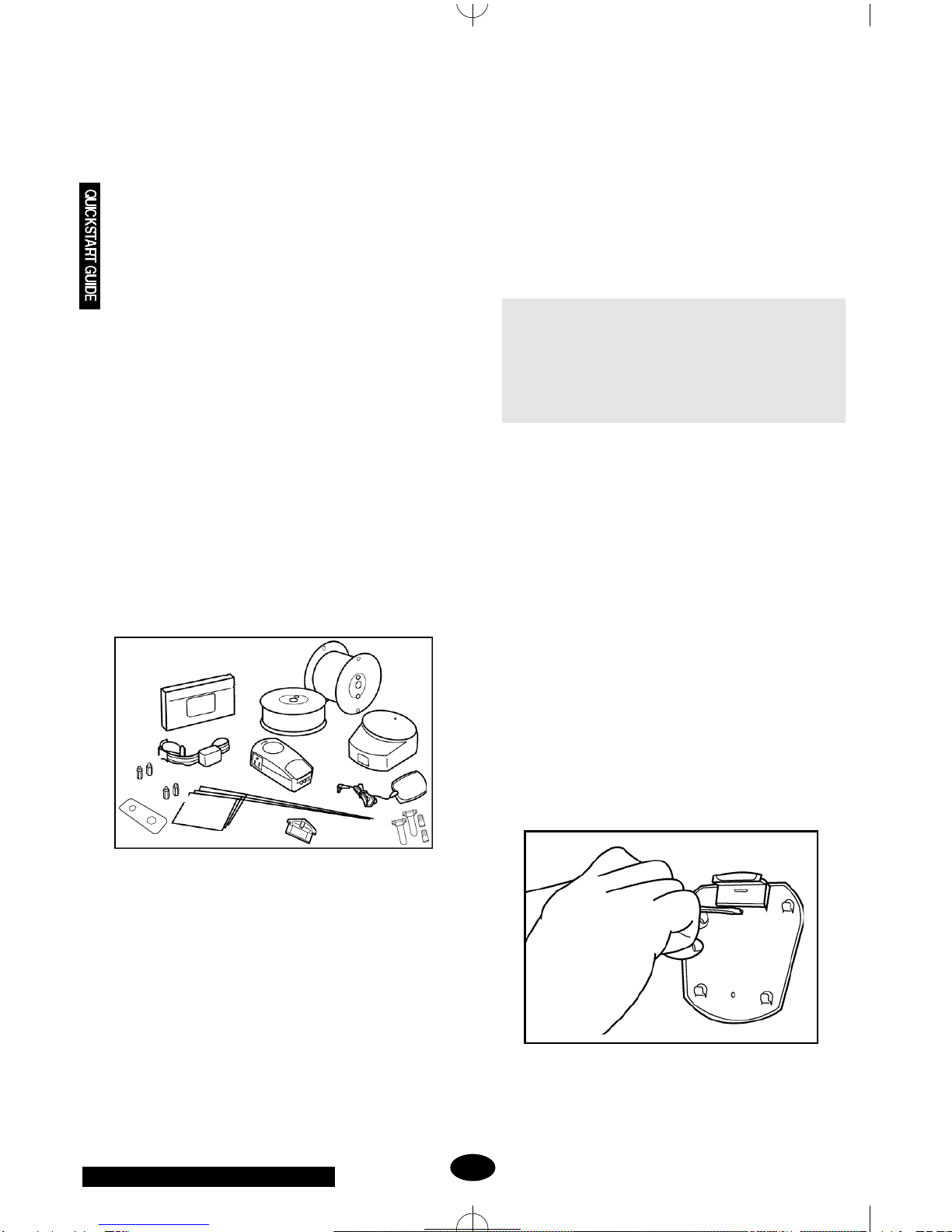
COMPONENTS
A. One waterproof collar receiver with reflective nylon
strap and quick-release buckle
B. One wall-mount transmitter with installation hard-
ware
C. One 24-volt, 400 milliamp AC adapter to power the
containment system
D. One lightning/power surge protector (SD-2200
model only)
E. One test lamp for testing the collar receiver
F. Fifty boundary flags
G. 20 ga.boundary wire (500 feet)
H. 20 ga.pre-twisted containment wires (100 feet) (SD-
2200 model only)
I. Interchangeable collar receiver probes for longhaired
and shorthaired dogs (one set each)
J. Black plastic training probes for use in the first train-
ing lesson
K. Four waterproof splices (wire nut and waterproof
capsule)
L. One probe wrench
M. Instructional training video
QUICK START GUIDE
READ THE IMPORTANT SAFEGUARDS SECTION OF
THISMANUALANDALLCAUTIONSANDWARNINGS
PRIOR TO INSTALLING AND USING THIS SYSTEM.
IT IS RECOMMENDED YOU READ THE ENTIRE
MANUAL PRIORTOINSTALLATIONORUSEOFTHIS
SYSTEM.
This Quick Start Guide is provided for people who are
already familiar with electronic containment systems. It
also servesasa quick visualindextothedetailedinstal-
lation procedure included in this guide.If you find you
need more detail while using this Quick Start Guide,
simply refer to the procedure section referenced for
detailed instructions.
1. Layout your containment boundary(See Section
4.A, pg 7 for details)
Sketch your yard on a piece of graph paper and decide
where you would like to contain your dog. Section 4.A.
shows some sample layouts and provides some helpful
design tips. Before you decide where to bury your con-
tainment wire have your utility companies mark utility
lines.
2. Install the Wall-Mount Transmitter (See Section
4.B, pg 8 for details)
Select a dry, indoor location for the wall-mount trans-
mitter that is within five feet of a standard, grounded
110-volt household outlet.Attach the transmitter mount-
ing plate to the wall using the supplied hardware.
Remember to mount your transmitter in a location
A. B.
H. G.
M.
D.
F.
L. E.
I. C.
K.
2.
J.
Innotek,Inc.(800)-826-5527 www.innotek.net
where you will be able to hear any alarms.Making sure
the POWER switch on the transmitter is in the OFF
position, place 8 AA alkaline backup batteries (optional,
but recommended) in the battery compartment on the
back of the transmitter.Snap the transmitter onto the
mounting plate.
3.Set Up the Collar Receiver (See Section 4.C, pg 9
for details)
In preparation for setting up your boundary wire, the
rechargeable collar receiver must be given a full
charge. Set the transmitter POWER switch to OFF, set
the FIELD SIZE switch to SM, turn the FIELD WIDTH
knob to MIN. Cut a short piece of the boundary wire
(about 6 inches) and strip about 3/8 inch of insulation
from both ends. Insert the wire ends into the LOOP ter-
minals on the transmitter. Plug the AC adapter into the
power jack on the transmitter and plug the adapter into
a nearby 110-volt household outlet. Set the transmitter
POWER switch to the ON position to charge the collar.
Position the collar receiver in the charging cradle locat-
ed on the top of the wall transmitter.Orient the light on
the collar receiver towardthe end ofthe charging cradle
marked with an arrow. The transmitter light will flash
green approximately every two seconds while charging.
A full charge requires 14 hours. When charging is com-
plete,thelightonthetransmitter willappearsolidgreen.
If the green light is not blinking, make sure the receiver
is oriented properly in the charging cradle. Be sure the
transmitter is turned on and check all connections.
After the receiver has been fully charged, set the
POWER switch to the OFF position, remove the short
piece of boundary wire, and unplug the AC adapter
from the wall outlet.
NOTE: The transmitter will not recharge the collar
receiver if a piece of boundary wire is not installed.
4. Plan the BoundaryWire Placement (See Section
4.D, pg 9 for details)
For the system to work properly, the wire must make
one continuous loop.When placing the wire, keep in
mind that you will want at least an 8- to 12-foot contain-
ment field (8 to 12 feet on each side of the wire).
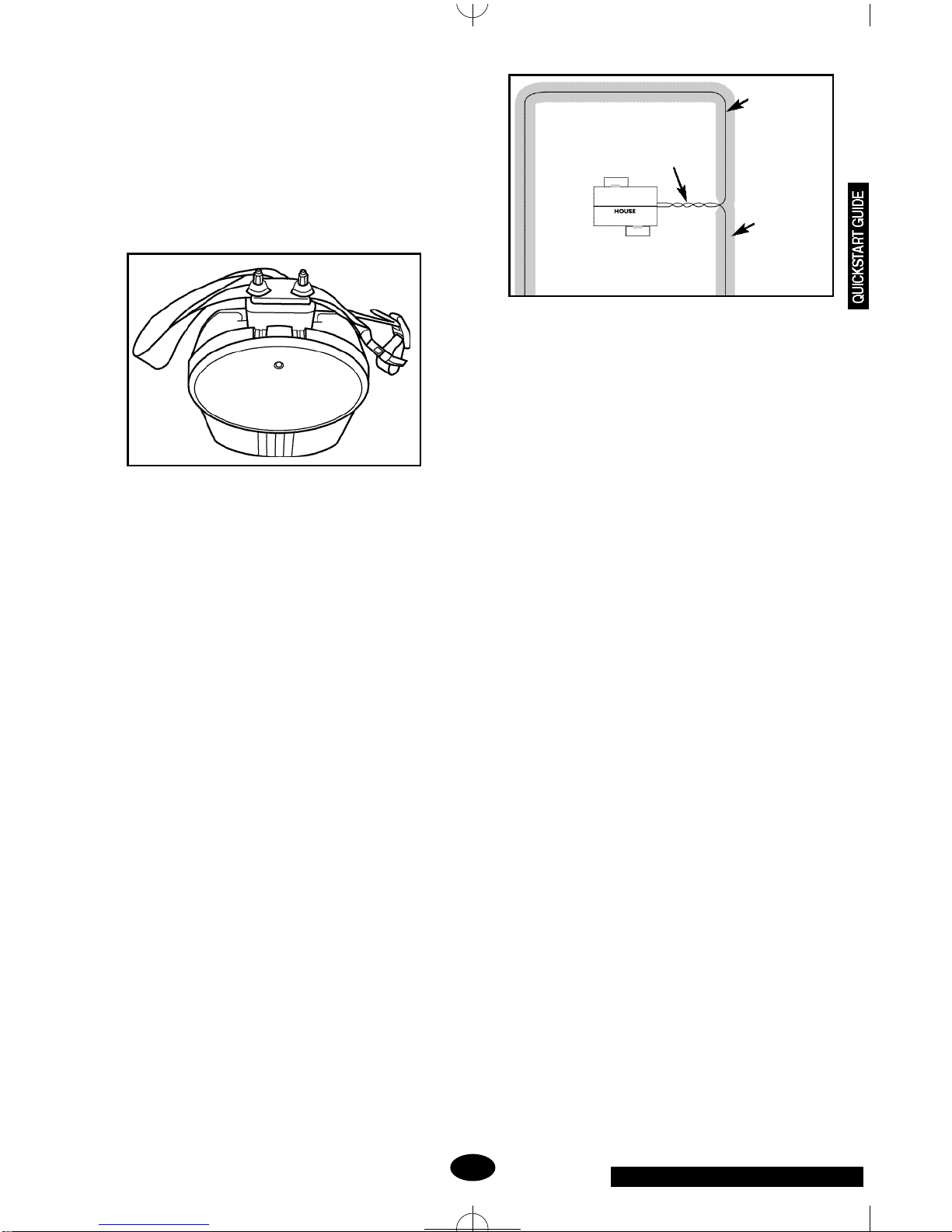
5.Place the Wire (See Section 4.E, pg 10 for details)
Placeyourboundary wireontop of thegroundfollowing
the tips listed in Section 4.D.Use twisted wire to con-
nect the transmitter to the boundary wire. Use the sup-
plied waterproof splices to make proper connections as
described in Section 4.F.2.
DO NOT BURYTHE WIRE UNTILYOUHAVETESTED
THE SYSTEM AND ARE SURE IT IS WORKING
PROPERLY. TAKE CARE NOT TO NICK OR SCRAPE
THEWIREINSULATIONDURINGINSTALLATION. AN
INTERMITTENT SIGNAL OR NO SIGNAL MAY
OCCUR.
6. Make the Final Connections (See Section 4.F, pg
10 for details)
Determine where the boundary wire will enter the build-
ing and drill a 1/4 inch hole through the wall, making
sure there are no wires, cables or pipes in the area you
are drilling.Make sure the POWER switch on the trans-
mitter is in the OFF position.
If installing the SD-2200 system, plug the Lightning
Protector into a nearby standard, grounded 110-volt
household outlet. Use the supplied twisted pair wire to
connect your boundary wire to the LOOP terminals on
the Lightning Protector and to connect the TRANSMIT-
TER terminals on the Lightning Protector to the LOOP
terminals on the transmitter.Plug the AC adapter into
theLightningProtectorandplug the other endoftheAC
adapter into the PWRjack on the transmitter.
IfinstallingtheSD-2100system,twistwireasdescribed
in Section 4.D.3. to connect your boundary wire to the
LOOP terminals on the transmitter.Plug the AC adapter
into a nearby standard 110-volt household outlet and
plug the other end of the AC adapter into the PWR jack
on the transmitter.
Set the FIELD SIZE switch to SM if you are using less
than 1000 feet of boundary wire or to LG if the bound-
ary wire is longer than 1000 feet. Verify that your dog is
3.
Twisted pair to transmitter;
cancels containment field
Boundary wire
Containment
field (invisible);
8 - 12’width;
follows loop of
wire along
entire length

Innotek,Inc.(800)-826-5527 www.innotek.net
not wearing the collar and no one is touching the collar
receiverprobes,settheFIELDWIDTH knob to MINand
slide the transmitter POWER switch into the ON posi-
tion. A green indicator light should illuminate on the
transmitter indicating a properly connected boundary
loop. If the green indicator light does not illuminate,
refer to the Section 8, pg 17 to troubleshoot the instal-
lation.
7.Test the system (See Section 4.H, pg 12 for details)
Make sure no one is touching the collar receiver
probes. Set the transmitter's FIELD WIDTH adjustment
knob to the 9 o'clock position and set the transmitter
POWER switch to the ON position. Attach the test light
to the probes and slowly walk the collar receiver toward
the center of a 50 foot straight section of the boundary
wire with the collar receiver held at the height of your
dog's neck with the probes pointed upward. Listen for
the warning sound and watch for the test light to illumi-
nate. The containment field should extend at least 8 to
12 feet on each side of the wire. To increase the field
width, rotate the FIELD WIDTH adjustment knob clock-
wise and recheck the distance the signal is broadcast-
ing from the wire.To decrease rotate Field Width count-
er clockwise; recheck. Repeat this procedure until you
are satisfied with the width of the stimulation field
throughout the installation.
8. Bury the BoundaryWire and Place Flags (See
Section 4.I, pg 13 for details)
Set the Power switch to OFF and disconnect the AC
adapter. Bury the wire about 3 to 4 inches deep where
the wire first enters the ground near the transmitter and
continue around the path of the loop wire at a depth of
at least 1 inch (you may wish to rent a slit trencher for
this purpose). Be careful you don't nick the wire insula-
tion as you place the wire in the ground. Leave some
slack in the wire to compensate for expansion and con-
traction due to temperature changes.Repeat the test
from Step 7 until you are satisfied with the field width
setting. As you approach the boundary wire, place a
flag at the point where the receiver first detects the
warning sound. Continue placing the flags at 6 to 8 foot
intervals around the entire containment area using this
technique. Don't forget to caulk and seal the interior
and exterior holes you made for the wire to prevent
damage from moisture. You are now ready to proceed
with Sections 5 through 7 for detailed instructions on
using the system and training your dog.
SECTION 1.
THE WALL-MOUNT TRANSMITTER
Thewall-mounttransmitterisyoursystem'scontrolcen-
terandworkswith the collarreceiverandboundary wire
to keep your dog safely contained within an area you
select. The front cover of the wall transmitter lifts up to
reveal switches that will customize your containment
system (see pg.5 for diagram).
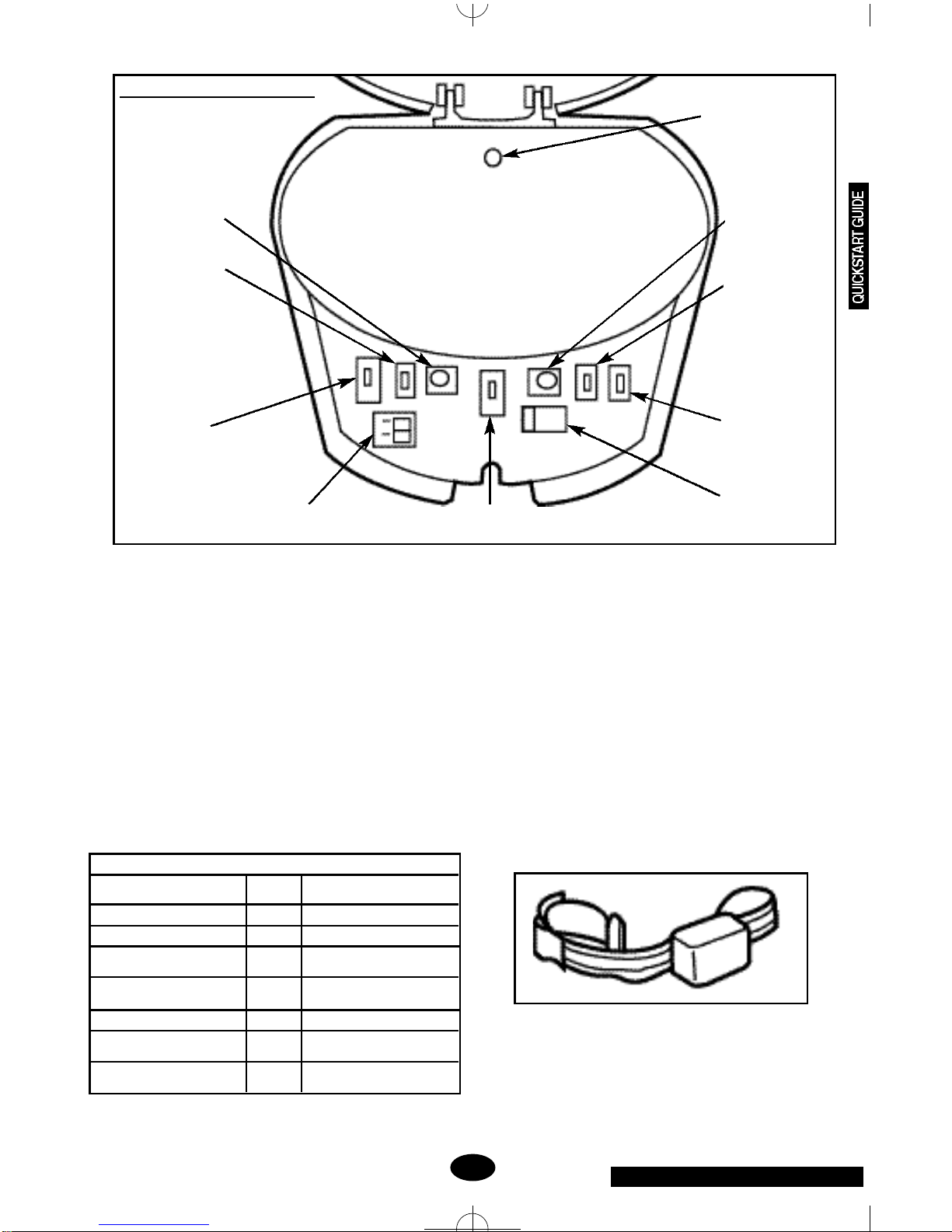
1. Field Width Adjustment -The FIELD WIDTH knob con-
trols the distance from the wire that your dog will receive the
warning sound and stimulation. With the supplied test light on
the collar receiver, always test this function at multiple loca-
tions in your containment area before putting the collar on
your dog.
2.Field Size-TheFIELDSIZEswitch allows you toselectthe
appropriate setting based on the size of your installation. The
SM setting is for properties using 1000 feet of wire or less.
The LG setting is for all installations using over 1000 feet of
wire.
3.Stimulation Level Switch (STIM LEVEL) - Positioning the
STIM LEVEL switch to LOW, MED, or HI selects the stimula-
tion level your dog receives as he enters the containment
field. The LOW setting administers a 2-second warning
sound, followed by a low level of stimulation if your dog does
not return to a safe area. The MED setting administers a 2-
second warning sound, followed by a medium level of stimu-
lation if your dog does not return to a safe area. The HI set-
ting delivers an immediate high level of stimulation without
any warning sound prior to the stimulation.
4.Loop Wire Terminals -The containment wires connect to
the wall transmitter through the bottom of the case and slide
into the terminal blocks marked LOOP.
5.Charge Reminder for Collar Receiver - The REMINDER
switch allows you to select a reminder interval of 60 (Labeled
A) or 30 (Labeled B) days or turn the function OFF. The timer
starts when the collar receiver is removed from the charger.
Thisswitchshouldbesetatatimeintervalthatwillremindyou
to check the collar receiver and verify that it has an adequate
charge to contain your dog. You should check the collar
receiver for a low battery indication before you put it on your
dog.
6.Power Connection (PWR)-The powerforthecontainment
system is provided by a supplied 24-volt, 400-milliAmp AC
adapter inserted into the power jack.
7.Battery Backup Monitor - If power to the system is inter-
rupted, backup power is provided by installing eight AA
Alkaline batteries (not included) in the holder on the backside
of the transmitter housing. Only use Alkaline batteries. The
4.
Innotek,Inc.(800)-826-5527 www.innotek.net
BatteryBackup Monitor will sound toindicate theAA batteries
need to be changed. This alarm can be turned ON or OFF by
the switch inside the transmitter. For the safety of your dog,
this feature should be turned on and the batteries kept in
working order at all times.
8.Power-The containmentsystem canbe turned on or offby
sliding the POWER switch to the ON or OFF position.
9.Alarm Volume -The volume of the alarm indicator can be
adjusted using the ALARM VOLUME knob.
10.Indicator Light and Alarm -The light located on the front
face of the transmitter will indicate the following conditions:
Notes:
1. Alarm tone twice per second.
2. Three one second reminder tones every minute. Reset by
placing the receiver on the charge cradle for more than 5 min-
utes.May be turned off by placing charge REMINDER switch
in the OFF position.
3. Alarm tone once per second when BACKUP BATTERY
monitor switch is set to ON. May be turned OFF by placing
switch in OFF position.
4. Alarm tone once every 5 seconds.
A chart of the indicator light and alarm conditions has been
placed inside the transmitter cover for your convenience.
SECTION 2.
THE COLLAR RECEIVER
Thecollarreceiveriswaterproof,rechargeable,andcan
be mounted on any non-metal strap.The probes are
available in long and short lengths to be used on long-
haired and shorthaired dogs, respectively.
Note: The collar receiver is always on and ready to
respond to the containment field when the battery is
properly charged.
1.Field Width
Adjustment Control
2.Field Size Switch
3. Stimulation
Level Switch
4. Loop Wire Terminals 5. Receiver Collar
Charge Reminder
6. Power Connection
7. Battery Backup
Monitor
8. Power ON/OFF
Switch
9. AlarmVolume
Control
5.
TRANSMITTER STATUS INDICATIONS
STATUS LIGHT ALARM CONDITION
TONE
SOLID GREEN NO POWER ON / SYSTEM OK
FLASHING GREEN NO RECEIVER CHARGING
FLASHING RED YES1BOUNDARY WIRE BROKEN
OR DISCONNECTED
FLASHING RED AND GREEN YES2RECEIVER RECHARGE
REMINDER
FLASHING YELLOW YES3BACKUP BATTERIES LOW
NONE YES4AC POWER DISCONNECTED
OPERATING ON BATTERY
NONE NO TRANSMITTER IS OFF OR
POWER IS DISCONNECTED
10. Indicator Light
WallTransmitter–User Controls
This manual suits for next models
1
Table of contents
Other Smart Dog Pet Care Product manuals


