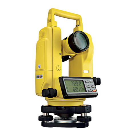
SMART MAX GEOSYSTEMS DE2A User manual

SMART MAX GEOSYSTEMS CO.,LTD
www.smartmaxgeosystems.com info@smartmaxgeosystems.com
SMART MAX GEOSYSTEMS
DE2A & DE2A-L Theodolite Manual

SMART MAX GEOSYSTEMS CO.,LTD
www.smartmaxgeosystems.com info@smartmaxgeosystems.com
Precaution
1) If the instrument has not been used for a long time, check it
regularly(3 monthes).
2) Avoid shocking or bumping.
3) No using in high dusty, not well ventilated, and easy burning
environment.
4) No dismount and mount the instrument by yourselves.
5) Prohibit to see the sun with telescope.
6) Cover with umbrella in burning sun or rainy day.
7) Cover the instrument with rainy cover.
8) Power off before taking off battery, or the data will be lost.
9) Place instrument the case and avoid humidity.
10) Prohibit move the instrument with tripod.
11) It will cause measuring result is not correct if there is leaves
and obstacle between the target and the instrument.
12) Place the instrument like the picture below:
13) Contact me if you got any problem.

SMART MAX GEOSYSTEMS CO.,LTD
www.smartmaxgeosystems.com info@smartmaxgeosystems.com
Contents
1. Description of All Parts………………………………1
1.1 Name of Parts ……………………………………………1
1.2 Display …………………………………………………3
1.3 Operation Key …………………………………………4
1.4 RS 232 ……………………………………………………6
2. Battery……………………………………………………6
2.1 Battery Replacement……………………………………6
2.2 Battery Recharging ………………………………………7
3. Measurement Preparation …………………………7
3.1 Instrument Setting Up……………………………………7
3.2 Instrument Leveling………………………………………7
3.3 Centering with Optical Plummet…………………………9
3.4 Eyepiece Adjustment and Object Sighting………………9
3.5 Power on ………………………………………………10
3.6 Power off………………………………………………10
4. Angle Measurement …………………………………11
4.1 Measuring Horizontal Angle Right and Vertical Angle …11
4.2 Switching Horizontal Angle Right/Left …………………12
4.3 Setting Horizontal Angle ……………………………13
4.4 Vertical Angle Percent Grade (%) Mode ………………14
4.5 Compasses (vertical angle) ……………………………15
4.6 Remeasuring Horizontal Angle…………………………15

SMART MAX GEOSYSTEMS CO.,LTD
www.smartmaxgeosystems.com info@smartmaxgeosystems.com
5. Distance Measurement………………………………17
6. Distance Measurement through the crossline in
the telescope………………………………………… 19
7. Laser Measurement…………………………………20
7.1 Orientation Measurement ……………………………… 20
7.2 Angle Designment……………………………………20
7.3 Zeith Measurement ……………………………………21
7.4 Level Measurement ……………………………………21
8. Parameter Setting Up………………………………22
8.1 Enter into Setting up Parameter ………………………22
8.2 Setting up Parameter ……………………………………23
9. Check & Adjustment………………………………24
9.1 Check & Adjustment of Plate Vial………………………24
9.2 Check & Adjustment of Circular Vial …………………26
9.3 Check & Adjustment of Optical Plummet………………26
9.4 Check & Adjustment of Inclination of Reticle…………28
9.5 Check & Adjustment of discrepancy between twice
collimation errors(C)………………………………… 29
9.6 Check & Adjustment of Vertical Index(i angle) ………30
9.7 Check & Adjustment of the laser confocal and coaxial… 31
10. Technical Index………………………………………33
11. Packing List …………………………………………35
12. Erorr Code Instruction ……………………………36

SMART MAX GEOSYSTEMS CO.,LTD
www.smartmaxgeosystems.com info@smartmaxgeosystems.com
1
1. Description of All Parts
1.1 Name of Parts
1.Telescope 2.Main body 3.Left Side Cover
4.Series No. 5.Optical Plummet 6.Circular Vail
7.Leveling Screw 8.Tribrach
9.Connection Knob on Tribrach 10.Soft Key
11.Display 12.Function Key 13.Plate Vial
14.Vertical Tangent Screw 15.Vertical Clamp Screw
16.Objective Lens

SMART MAX GEOSYSTEMS CO.,LTD
www.smartmaxgeosystems.com info@smartmaxgeosystems.com
2
17. Handle 18.Handle Screw 19. Battery locking Lever
20. Battery 21. Grip 22. Eyepiece
23.Right Side Cover 24. Horizontal Tangent crew
25. Horizontal Clamp Screw 26.RS232 Port

SMART MAX GEOSYSTEMS CO.,LTD
www.smartmaxgeosystems.com info@smartmaxgeosystems.com
3
1.2Display
The figure LCD can display angle,characters,date and time,etc.
There are two modes on display:Measurement Mode & Menu
Mode.
Display(example):
①Angle
Measurement Mode
②Distance
Measurement Mode
③Remeasurement Mode
④Menu Mode
ANG 08-01-02 12:00
V :81°54′21″
HR:157°33′58″
08-01-02 12:00
n - 0 T-0
HR :57°33′58″
08-01-02 12:00
S.E.T.-1
OFF
DIST 08-01-02 12:00
0.000 m
HR:157°33′58″

SMART MAX GEOSYSTEMS CO.,LTD
www.smartmaxgeosystems.com info@smartmaxgeosystems.com
4
Symbol
Contents
Vertical compensation
Horizontal remeansure
Automatic Power off
Battery
Horizontal locked
Special Function,press ¤ twice,it will be disappeared
%
Gradient Display
b-OUT
Vertical angle is over the compensation
OUT
Slope is over ±100%
m
Meter unit
°′″
Set 360°as angle unit
1.3 Operation Key
The function of the soft key is different in different
measurement mode.
①Angle Measurement Mode
REP▲ Power
◆¤
ANG 08-01-02 12:00
V :81°54′21″
HR :157°33′58″

SMART MAX GEOSYSTEMS CO.,LTD
www.smartmaxgeosystems.com info@smartmaxgeosystems.com
5
ANG▼ ENT
L/R HOLD % 0SET
Soft Key
Function
L/R
Switches R/L rotation of horizontal angle
HOLD
Hold the horizontal angle
%
Vertical angle percent grade(%) mode
0SET
Set horizontal angle as 0°00′00″
②Distance Measurement Mode
REP▲ Power
◆¤
ANG▼ ENT
SD HD VD TR
Soft Key
Function
SD
Enter into SD Measurement
HD
Enter into HD Measurement
VD
Enter into VD Measurement
TR
Enter into TR Measurement
DIST 08-01-02 12:00
0.000 m
HR:157°33′58″

SMART MAX GEOSYSTEMS CO.,LTD
www.smartmaxgeosystems.com info@smartmaxgeosystems.com
6
③Special function Measurement mode(This will be valid only
in the Angle Measurement Mode)
Soft Key
Function
First press ¤, when it
display , press▲
Turn on /off laser alignment
First press ¤, when it
display , press▼
Turn on /off laser plummet
First press ¤, when it
display , press◆
Turn on /off LCD
First press ¤, when it
display , press ENT
Enter into Menu mode,press ENT
one more time will save and exit
1.4 RS232
RS232 is used to connect the Theodolite with computer or PC to
transfer measured data to computer or PC.
2. Battery
2.1 Battery Replacement
1. Battery Insert
Insert battery correctly. Check and
insert battery holder true to side into
the housing.

SMART MAX GEOSYSTEMS CO.,LTD
www.smartmaxgeosystems.com info@smartmaxgeosystems.com
7
2. Battery Removement
Remove battery and replace.
2.2 Battery Recharging
1. Insert recharger into battery’s hole.
2. Insert the plug of the recharger into 220VAC power supply. It
shows green light after finishing recharging.
3. Cut the power supply of the recharger and drew the battery out
from the recharger.
3. Measurement Preparation
3.1 Instrument Setting Up
1. Setting up the tripod.Pull out to
required length and tighten screws.

SMART MAX GEOSYSTEMS CO.,LTD
www.smartmaxgeosystems.com info@smartmaxgeosystems.com
8
2. Place the INSTRUMENT onto
the tripod head. Tighten central fixing
screw of tripod.
3.2 Instrument leveling
1.Level the instrument with circular vial
a. Turn the leveling screw A and B
to move the bubble in the circular vail.
The bubble is now located on a line
perpendicular to a line running through
the centers of the two leveling screw
being adjusted.
b. Turn the leveling screw C to bring
the bubble to the center of the circular
vail.
2. Level the instrument with plate vial
a. Rotate the instrument horizontally
by loosening the Horizontal Clamp
Screw and place the plate vial parallel with the line connecting
leveling screw A and B, and then bring the bubble to the center of
the plate vial by turning the leveling screwsA and B.

SMART MAX GEOSYSTEMS CO.,LTD
www.smartmaxgeosystems.com info@smartmaxgeosystems.com
9
b. Rotate the instrument 90º (100g) around its vertical axis and
turn the remaining leveling screw or leveling C to center the
bubble once more.
c. Repeat the procedures 1& 2 for each 90º (100g) rotation of the
instrument and check the whether the bubble is correctly centered
for all four points.
3.3 Centering by optical plummet
Adjust the eyepiece of the optical plummet telescope to your
eyesight. Slide the instrument by loosening the tripod screw,
place the point on the center mark of the optical plummet. Sliding
the instrument carefully not to rotate that allows you to get the
least dislocation of the bubble.
Note:Centering by foot screw first and then leveled-up by
tripod.
T/S Point
center
mark of
the optical
plummet

SMART MAX GEOSYSTEMS CO.,LTD
www.smartmaxgeosystems.com info@smartmaxgeosystems.com
10
3.4 EyepieceAdjustment and Object Sighting
1. Sight the Telescope to the sky and rotate the eyepiece tube to
make the reticle clear.
2. Make the target image clear with the telescope focusing
screw. If there parallax when your eye move up, down or left,
right, that show the diopter of eyepiece lens or focus is not
adjusted well and accuracy will be influenced, so you should
adjust the eyepiece tube carefully to eliminate the parallax.
3.5 Power on
1.Leveling INSTRUMENT
2. Press the Power key (red
k
ey).
3. Turn telescope to
initial the INSTRUMENT.
Power
08-01-02 12:00
V0 S.E.T.
ANG 08-01-02 12:00
V :81°54′21″
HR:157°33′58″

SMART MAX GEOSYSTEMS CO.,LTD
www.smartmaxgeosystems.com info@smartmaxgeosystems.com
11
Confirm the battery is full,
if not so,please replace and
recharge the battery.
3.6 Power off
Press the Power key (red key).
4. Angle Measurement
4.1 Measuring Horizontal Angle Right and Vertical
Angle
Operation Procedure
Display
①Press ANG to enter into
Angle Measurement.
Aim at the first target A
测角 08-01-01 12:12 Φ
+垂直: 81°54′21″
水平右:157°33′58″
ANG 08-01-02 12:00
V :81°54′21″
HR:157°33′58″

SMART MAX GEOSYSTEMS CO.,LTD
www.smartmaxgeosystems.com info@smartmaxgeosystems.com
12
②Press 0SET to set
horizontal reading of target
A as 0°00′00″
③Aim at the second target
B. The required V/H angle
to target B will be
displayed.
★Press ENT,the vertical and horizontal angle can be sent out
through RS232.
How to Collimate (Reference)
1. Point the telescope toward the light. Turn the diopter ring and
adjust the diopter so that the cross hairs are clearly observed.
(Turn the diopter toward you first and then backward to focus).
2. Aim the target at the peak of the triangle mark of the sighting
collimator. Allow a certain space between the sighting collimator
and yourself for collimating.
3. Focus the target with the focusing knob.If parallax is created
between the cross hairs and the target when viewing vertically or
horizontally while looking into the telescope, focusing is
incorrect or diopter adjustment is poor. This adversely affects
ANG 08-01-02 12:00
V :81°54′21″
HR:0°00′00″
ANG 08-01-02 12:00
V:81°54′21″
HR:57°33′58″

SMART MAX GEOSYSTEMS CO.,LTD
www.smartmaxgeosystems.com info@smartmaxgeosystems.com
13
precision in measurement or survey; eliminate the parallax by
carefully focusing and using diopter adjustment.
4.2 Switching HorizontalAngle Right/Left
Operation Procedure
Display
①Press ANG to enter into
Angle Measurement.
②Press L/R. The mode
Horizontal angle Right
(HR) Switches to (HL)
mode.
★Press L/R to switch Right mode and Left mode.
★Press ENT,the vertical and horizontal angle can be sent out
through RS232.
4.3 Setting Horizontal Angle
Setting by Holding the Angle
Operation Procedure
Display
ANG 08-01-02 12:00
V:81°54′21″
HR:100°00′00″
ANG 08-01-02 12:00
V :81°54′21″
HL:260°00′00″

SMART MAX GEOSYSTEMS CO.,LTD
www.smartmaxgeosystems.com info@smartmaxgeosystems.com
14
①Press ANG to enter into
Angle Measurement.
②Set the required
horizontal angle, using
Horizontal tangent
screw.Then press HOLD.
③Aim at the target which
need to be set up the angle
④Press the ENT to finish
holding the horizontal
angle.The display returns
back to normal angle
measurement mode.
ANG 08-01-02 12:00
V :81°54′21″
HR:100°00′00″
ANG 08-01-02 12:00
V :81°54′21″
HR:100°00′00″
ANG 08-01-02 12:00
V :81°54′21″
HR:100°00′00″
ANG 08-01-02 12:00
V :81°54′21″
HR:100°00′00″

SMART MAX GEOSYSTEMS CO.,LTD
www.smartmaxgeosystems.com info@smartmaxgeosystems.com
15
4.4 Vertical Angle Percent Grade (%) Mode
Operation Procedure
Display
①Press ANG to enter into
Angle Measurement.
②Press % to enter into
Slope Measurement.
★The display mode switches when pressing % key every time.
★While the measurement is carried out over ±45º(±100%)
from the horizontal,the display shows <OUT>.
4.5Compasses (vertical angle)(Refer to Parameter
Setting Up)
Vertical angle is displayed as shown below:
ANG 08-01-02 12:00
V :81°54′21″
HR:100°00′00″
ANG 08-01-02 12:00
V :50 %
HR:100°00′00″

SMART MAX GEOSYSTEMS CO.,LTD
www.smartmaxgeosystems.com info@smartmaxgeosystems.com
16
4.6 Remeasuring HorizontalAngle
Operation Procedure
Display
①Press REP to get into the
mode of Horizontal Angle
Remeasurement
08-01-02 12:00
n - 0 T-0
HR:57°33′58″
This manual suits for next models
1
Table of contents
Other SMART MAX GEOSYSTEMS Laser Level manuals
Popular Laser Level manuals by other brands
RedBack Lasers
RedBack Lasers LSR Series instructions
Bosch
Bosch GLL 2-50 Professional Original instructions
Kärcher
Kärcher SP 17.000 Flat Level Sensor manual

Craftsman
Craftsman 320.48293 Operator's manual
Hilti
Hilti PR 30-HVSG A12 operating instructions
LaserLiner
LaserLiner PrecisionCross-Laser PCL 8 operating instructions

