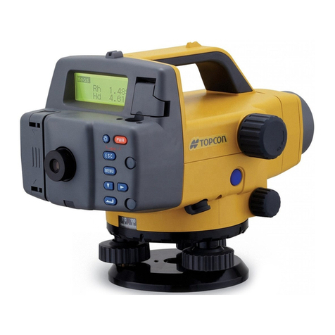
Topcon AT-G4 User manual

#TOPCOR
INSTRUCTION
MANUAL
AUTO LEVEL
AT-G4
AT-G6

Congratulations
on
your
choice
of
the
TOPCON
Auto-Level,
in
the
AT
G Series,
which
we are
sure
will serve
you
well
and
continue
to
give
you
full
satisfaction
for
many
years
to
come
The
TOPCON
Auto-Levels
are
precision
instruments,
which
should
be
handled
in
the
recommended
manner.
Therefore,
it is
recommended
that
you
carefully
read
this
manual
before
you
use
the
inst
rument
in
the
field,
even
if
you
have
had
previous
experience
with
TOPCON
surveying
instruments.
Th1s
manual
will
not
only
introduce
you
to
its
operation,
but
will give
you
some
information
on
its
construction.
as well as
adjustments,
so
that
you
may
use
the
instrument
with
maximum
efficiency
and
obtain
optimum
performance
from
it,
as well as
extend
its service·life.
Specifications
and
designs
of
the
AT-G
Series
Auto-Levels
are
subject
to
changes.
when
found
necessary
to
improve
the
quality
of
the
instrument,
without
advance
notice.
M'TOPCOI\

IMPORT
AN
T
(
1)
Readings
will
be
incorrect,
if
the
eyep1ece
has
not
been
properly
adjusted
for
the
use
r's eyesight and/
or
if focus-
ing
is
improper, since this
will
mtroduce parallax and,
therefore, give wrong results.
(2) Always rotate the fine
horizontal
knob
in
the tightening
direction,
or
in the clockwise
direciton,
and stop, when
fixing
a sight.
(3) For high precision surveying operations, always cover
the instrument and
tripod
with
some
type
of
awning or
umbrella
to
shield them
from
strong sunlight_
(4) Protect the instrument
from
shock and vibrations, when
carrying
or
transporting the instrument.
(5)
After
using the instrument, brush away dust
on
all
exposed surfaces, then wipe clean and
dry
and,
finally,
store (in the carrying
case)
in
a well-ventilated location.
(6) When the lens surface must
be
cleaned, always brush or
blow
dust
or
dirt
away first,
with
the cleaning brush
or
a
rubber-ball air blower. Then, wipe the surface gently
with
a
soft
well-washed
cotton
cloth
or
lens cleaning
tissue.
If
necessary,
dip
lightly
in
alcohol
or
a
mixture
of
alcohol and
other
and then wipe the lens surface gently
with
ever-widening circular
mot
ions,
from
the center
out.
Do
not
rub
the lens surface
on
any
cond
i
tion
but
repeat,
if
found
necessary.
(7} Clean the plastic carrying
case
with
neutral detergent
or
water.
Do
not
use
benzine, th1nner
or
any
other
chemi-
cal
solutions.
(8)
Use
tripods
with
a
tripod
screw
of
5/8
in. diameter and
11
threads per inch,
as
per J I S B standards.
(9) Do
not
dismantle the telescope
or
revolving parts
of
the
instrument. Contact the nearest experienced and well-
equipped factory,
if
you
think
that
the instrument must
be overhauled
or
repaired.
C
ONTENTS
FEATURES
STANDARD SET COMPOSITION
..
....
-
....
-
..
--
..
-- 2
OPTIONAL ACCESSORIES
....
..
·
......
..
-
......
-
..
· 2
NOMENCLATURE
..
·--
..
-- --
....
--
..
--- ---
....
· ·
....
· 3
BASIC OPERATING PROCEDURES --
......
·
....
-
......
5
1.
Setting
Up
the Tnpod · · ·· ·
·-
· · ·
·-
· · · · ·· · ·
·-
·· · · · · 5
2.
Attaching
the Instrument
to
the Tripod Head
·-
· · · ·· · 6
3.
Setting
the Instrument
Up
Over
the Pomt · · ·· · · · ·· · 6
4. Leveling the
Instrument
· · · · ·· · · ·· ·· · · · · · ·· · ·· · · · ·· · 7
5. Adjusting the Eyepiece ·· · · · ·· · · ·· · · ·· · · •·· · · ·· · · ·· · · 8
6. Sighting and
FOCUSing
..
--
......
•
....
·
....
·--
..
..
··
..
8
OPERATI
ONS
--
..
--
..
·
..
--·
--
..
--
..
···
..
..
........
....
·
10
1. Leveling
or
Determing
the
Differeces
in Elevation · ·
10
2. Measuring a Honzontal Angle · · · · ·· ·
·-
·· · · · ·· · · · ·· ·
11
3. Stadia
Survey
1ng · · · · · ·· · ·· ·· · · ·· · · · · ··· · · ·· · · · ·· ·
12
ADJUSTMENT
--
--
..
--
---
..
·
..
·· --
....
-- ·14
Adjustment
of
th
e
C1
rcu
lar
Level
...
....
.............
--
14
Co
lh
mat
1on
of
the
In
s
tru
me
nt
-- · -- ·
..
·--
..
--
----
·
..
·--
16
OPTIONAL
ACCESSORIES · · ·· · · · · · ·· · · · ·· · · ·· · · · · ·· --
19
1. Alminum Tripod, Type E · · ·· · · · ·· ·· · · · ·· · · ·· · · · · · · · ·19
2. Alminum Tripod, Dome Head ·
·-
·· · · · · ·· · · · · ·· · · ·· · ·· 19
3. Plumbing Bob · ·· · · · ·· · · ·· · · ·· · · · · ·· · · ·· · · · ·· · · · ·· · · · 19
SPECIFICATIONS ·· · · · · ·· · ·
..
·
..
· · ·
..
· · ·
..
·· ·
..
·· ·
..
·
..
20

FEATURES
" Fast
in
Speed and Stable
Automatic
Leveling
Action
The AT-G Series incorporates a magnettcally-damped
compensator
which
is
not
affected
by fme
vibration
s
and realizes
very
stable precision, thus enables
to
speed
up
the
automatic
leveling act1on
greatl
y and precisely.
Four special plastic ribbons are used
for
hangmg the
magnet
damper
compe
nsator
system and.
therefore
,
there
receives no 1nfluence
from
the
magnetic
field.
•
Water
Resistant Telescope
Construction
The instrument has a
comp
le
tely
water
resistant
tele-
scope and
th
us is ideal even
in
the
wet-surveying
op-
erations. such as
in
light rains
or
in the tunnel,
with
dry
gas (nitrogen) sealed inside the
te
lescope tube
which
effectively
prevents
condensations on
the
lens surface.
* Clampless Fine Horizontal Adjustments
Fine horizontal adjustments are possible
at
any
point
through
360
° (400g)
of
the arc,
without
clamping action,
thus speeding
up
target alignment, and fine horizontal
knobs are available on
both
sides,
for
very
easy
and
speedy adjustments.
* Horizontal Circle
The horizontal circle
is
graduated
from
0°
to
360°
(Og
to
400g) in clockwise direction in 1° (1g) spacing, and a
value
is
indicated
for
each
10
° (10g).
*
Very
Fast Instrument Set-Up
Very
fast instrument set-up
is
possible
because
the
base
plate can be used
for
fixing
on
top
of
dome head tripods,
such
as
the TOPCON Dome
Head
Aluminum
Tripod,
in
addition
to
standard
flat
head tripods.
STANDARD
SET COMPOSITION
A Model AT-
G4
or
AT-G6
B PlaSt
iC
carrying
case
C Lens
cap
D Instru
ction
manual
E Heaxagon
wrench
OPTIONAL
ACCESSORIES
1. Dome head alummum
trip
od
2. Type E aluminum
tnpod
3. Plump bob
set
2
each
each
each
each
each

NOMENCLATURE
1)
Aiming
sight
7)
Eyepiece cover
2)
Objective lens
8)
Base
plate
3)
Circular level viewing
mirror
9)
Focusing
knob
4) Telescope eyepiece 10)
Fine
horizontal knob
5)
Circular level 11) Leveling screws
6)
Horizontal circle
3 4

BASIC OPER
AT
ING PROCEDURES
1.
Setting
Up
the
Tripod
• Use
tripods
with
a
tripod
screw
of
5/8 in.
diameter
and
11
threads
per
inch,
as
per
J I S B
standareds,
such
as
the
TOPCON
Type
E
Aluminum
Tripod
or
Wide-frame
Wood-
en
Tripod
and
the
Dome
Head
Aluminum
Tripod.
1)
First,
extend
the
extension
legs
to
suitable
lengths
and
tighten
the
wing
nuts
on
their
mid
-
sections.
2)
Tighten
the
hexagonal
key
fastening
system
on
the
side
of
the
tripod
head
so
that
the
tripod
legs
don't
fall
too
loosel
y.
Place
the
tripod
over
the
required
point,
with
legs
spread
about
a
meter
apart
or
at
such
angle as will
insure
stabillity
of
the
tripod.
Place
one
tripod
leg in
position
and
then
used
the
other
two
to
approximately
level
the
tripod
hea
d.
If
necessary,
adjust
leg
extension,
too.
3)
Press
the
shoes
on
the
tripod
legs
firmly
into
the
ground
and
anchor
the
tripod
securely.
.-------
In
str
um
ent
5
2.
Attaching
the
Instrument
to
the
Tripod
Head
Take
the
instrument
carefully
out
of
the
carrying
case
and
place
it
on
the
tripod
head.
1)
AI
ign
the
tripod
screw
to
the
socket
on
the
base
of
the
instrument.
And,
when
aligned,
screw
in
the
tripod
screw
unt
il
the
instrument
is
securely
fixed
on
the
tripod
head.
2)
If
the
hor
iz
onta
l
circle
is
being
used
for
measuring
angles
or
establ
i
shing
a
line,
the
instr
ument
must
be
set
up
exactly
over
the
point
with
the
plumb
bob.
3) Use
three
leveling
screws
and
center
the
bubble
of
the
circular
level
or,
in
other
words,
level
the
instrument.
If a
dome
head
tripod
is
being
used,
in
this
case,
how-
ever,
simply
loosen
the
tripod
screw
slightly
and
move
the
instrument
around
on
top
of
the
tripod
head,
while
c
hec
king
the
circular
level.
When
the
bubble
is
located
inside
the
red-co
l
ored
circle, in
this
case,
tighten
the
tripod
socket
.
3_
Setting
the
Instrument
Up
Over
the
Point
When
the
instrument
is
used
to
measure
angles
or
to
es-
tablish
a line,
the
instrument
must
be
set
up
exactly
over
a
particular
point,
with
the
plumb
bob.
1)
Hang
the
plumb
bob
hook
on
the
plumb
bob
hanger
of
the
tripod
screw.
2)
Next,
suspend
t
he
plumb
bob
string
from
the
plumb
bob
hook
and
adjust
string
length
with
the
slipping
device
so
that
th
e
plumb
bob
is
at
a
suitable
height.
3)
If
the
instrument
has
not
been
set
up
over
the
re-
quired
point,
move
the
instrument
bodily
over
to
the
point,
without
disturbing
the
relation
between
tripod
legs
and
tripod
head.
Place
down
in
position
so
that
plumb
bob
is
about
one
centimeter
or
so
directly
over
the
point.
Grasp
two
of
the
tripod
legs
and
adjust
with
resp
ec
t
to
the
third
leg
so
that
the
tripod
head
is
level at a
convenient
height,
with
sufficient
spread
of
th
e legs,
when
the
two
legs
are
allowed
to
touch
ground.
6

4) Finally,
press
each leg
firmly
into
the
ground
while
watching
the
plumb
bob
and
tripod
head.
5)
Next, loosen the tripod screw slightly
and
slide the
instrument
on
top
of
the
tripod
head,
if
further
adjustment is required
to
position
the
plumb
bob
directly
over the
point.
Then, tighten the
tripod
screw.
4. Leveling the Instrument
1)
Use
the
two
leveling screws
(which
are
farthest
from
the
circular
level)
to
move
the
bubble
of
the
circular
level.
In
other words, rotate
the
screwS-
in
the arrow-
indicated opposite
directions
which
will
shift
the
bubble
of
the
circular
level so
that
it
is
locat
ed on a
line perpendicular
to
a line running through the cen-
ters
of
the
two
leveling screws being adjusted,
as
illustrated.
2)
Next,
revolve the remaining leveling screw and
shift
the bubble towards the center
of
the circular level.
Leveling screw C
If
the
bubble cannot be centered
properly,
repeat the
operation
from
the beginning.
NOTE:
Do
not
touch the telescope
during
this
procedure.
7
5. Adjusting the Eyepieces
The
telescope eyepiece should
be
adjusted
to
the user's
eyesight before conducting surveying operations.
1)
First,
point
the telescope towards the
light
and
rotate the eyepiece adjustment ring
fully,
by
revolv·
ing
it
in
the
counter
-clockwise direction. (The reticule
cross-hairs
will
be observed blurred and
indistinct,
at
this time.)
2)
Next,
slowly
rotate the ring
in
the clockwise direc·
tion.
Stop
revolving when
the
cross-hairs are
seen
clearly and
distinctly
in
the
field
of
view.
Always stop adjustments while racking
the
eyepiece
ring in.
6. Sighting and Focusing
1) Point
the
telescope
in
the
direction
of
the
target
.
Then, sight
through
the
aiming
sight and align
the
target
to
the
apex
of
the
triangular
mark
in
the
field
of
view,
as illustrated.
Aiming
sight
Aiming
sight-
-.---
-,
Focusing
~~
eyepiece
8

2) Next, focus
on
the
target,
by
revolving
the
focusing
knob
in
either
direction,
as
required.
3)
Finally, use
the
fine
horizontal
knob
for
precise align-
ment
of
the
target.
NOTE:
When precisely aligned,
shift
the
eye
to
the
left
and
right,
while looking
through
the
telescope
eyepiece.
There
sho
uld
be
no
deviations
between
the
reticule cross-hairs
and
the
target, in this case. If
there
is
parallax, which
means
that
either
focusing
is
incomplete
or
that
the
adjustment
of
the
eyepiece was
not
done
properly
or
botlh. In any case,
the
focusing
error
must
be
eliminated
by carefully focusing
or
adjusting
the
eyepiece
to
the
user's
eyesight.
OPERATIONS
1. Leveling
or
Determining
the
Differences in Elevation
The
primary
use
of
the
Auto-Level is,
of
course,
for
leveling.
The
purpose
of
leveling
is
,
of
course,
to
deter-
mine
the
elevation
of
a
point
or
the
difference
in
elevation
between
points. Since
the
line
of
sight
through
the
teles-
cope
of
the
Auto-Level,
which
is
properly
set
up,
is
horizonta
l,
the
differences
in
elevation
is
determined
by
measuring
from
th
is
horizontal
line
of
sight.
Rod(
1)
Rod(
II)
Back sight
Fo
res
igh
t
bA
~
Ho =
H•+•
HA
_j_
l__
Temporary
base
level
1)
Set
up
and
level
the
instrument
about
halfway
between
two
points,
say,
A
and
B,
if
possible.
2)
Sight
through
the
telescope
on
a leveling
rod
(I) held
on
top
of
point
A
and
note
the
rod
reading. (Say,
the
line
of
sight
is
back
towards
the
starting
point,
or
the
"back
sight",
and
the
rod
reading
is bA.)
3)
Next,
sight
through
the
telescope
on
a Ieveling
rod
(II)
held
on
top
of
point
B
and
also
note
the
rod
read-
ing. (The line
of
sight,
of
course,
will
now
be
in
the
direction
that
the
surveyor
is
go
ing
forward
to
and,
therefore,
will
be
the
"foresight",
with
the
rod read-
ing, say, fB.)
4) Since
both
sights
through
the
telescope
are horizon-
tal,
in
this
case,
the
difference in
the
rod
readings is
9
10

also
the
difference
in
elevation
or
height
(h},
or
h =
bA-
fB.
The
height
from
.
the
base
surface
or
level, in th is
case,
can
be
obtained
from
the
formula
-
Hs
=
HA
+ h
2. Measuring a Horizontal Angle
The
AT-
G
series
has
a
horizonta
l
circle
.whi
ch
can
be
used
for
measuring
an
angle.
The
horizontal
circle
is
graduated
in
one
degree
(1g)
divisions
but
numbered
every
10
degrees
(1
og},
with
the
scale
calibrated
from
0
to
350°
(0
to
390g},
with
the
value
increasing
as
the
i
nstrument
is
revolved
clockwise.
1}
First,
set
up
and
proper
ly
level
the
instrument
at
the
starting
point,
say,
Point
C.
Then,
sight
through
t
he
telescope
on
the
base
target,
say,
Point
A.
Align
the
rod
set
up
on
top
of
Point
A
precise
ly
to
the
ver
tical
cross-hair
line
of
the
te
le-
scope
reticule
with
the
fine
horizontal
knob.
Then,
rotate
the
horizontal
c i
rcle
ring
to
make
zero
setting
of
the
scale.
2}
Next,
si
ght
through
the
telescope
on
a
rod
held
on
top
of
Po
i
nt
8
and
precise
ly align
with
the
fine
hori-
z
ontal
knob.
The
reading
at
this
ti
me
will,
of
course,
be
the
horizontal
angle
between
Points
A
and
B,
from
Point
C,
or
the
ang
le ACB.
11
P
oint
A
Point
B
Po
int(A} D T
Point(B
)
egree
ype
10
0
390
•
•••••
•
••
Point(A} G d T
Point(B
}
ra
e
ype
3. Stadia Surveying
The
AT
- G
Series
Auto-Levels
can
be
used
for
stadia
sur-
veying,
which
is
simply
a
convenient
method
for
measur
-
ing
distances
with
t
he
stadia
hairs
of
the
instrumen
t, in
combination
with
a
graduated
rod,
such
as
leveling
rod
or
stadia
rod
(which
is
preferable
for
l
ong
distances}.
The
distance
from
the
center
of
the
instrument
to
the
rod
is
found
by
sighting
through
the
i
nstrument
on
to
the
rod
and
multiplying
the
stadia
interval
or
reading
(i.
e.,
the
interva
l
between
the
apparent
locations
of
the
bottom
and
top
stadia
hairs
on
the
rod}
by
100.
1«-
--L
= I
00
2
--
~
1) Fir
st
,
set
up
the
rod
on
the
point
.
2)
Then,
sight
through
the
tele
s
cope
of
the
properly
12

leveled
instrument
and
dete
r
mine
the
distance
or
in-
terval
"Q"
on
the
rod
between
the
bottom
and
top
stadia
hairs.
3)
The
horizontal
di
stance
" L"
from
the p
lu
mb
line
center
of
the
instrument
to
the
rod
is
equal
to
1
DO
times
the
stadia
interval
or
stadia
reading
or
rod
reading
or
"2".
If
the
line
of
si
ght
is inclin
ed,
however,
the
di
stance
obtained
by
the
above
stadia
met
h
od
must
be
re-
duced
to
its
corresponding
horizontal
distance
and
vertical
distance.
To
reduce
the
in
clined
or
slope
distance
"S",
in
this
case,
the
following
formulas
can
be
used:-
L = S-cos a
V =
1/2
S·sin 2a
When L
is
the
horizonta
l
distance,
V
the
vertica
l
distance
and
S
the
slope
distance.
13
ADJUSTMENT
The
Auto-Levels
in
the
AT-G
Series are all
exceptionally
sturdy
and
ruggedly
constructed
instruments,
in
spite
of
in-
corporating
automatic
leveling
systems
and
featuring
very
high
precision,
and,
therefore,
should
seldom
require
adjust
-
ments
.
Furthermore,
all
instruments
delivered
undergo
strict
and
rigid inspections,
from
the
time
the
raw
material
is delivered
to
the
factory
until
the
final
equipment
is
thoroughly
in-
spected
and
precisely
adjusted,
by
experienced
technicians,
and
then
carefully
packed
for
shipment
to
you.
Therefore,
unless
the
instrument
is
subject
to
excessive
rough
handling
during
transportation,
it
should
arrive
properly
adjusted
and
ready
for
immediate
use.
Even
if
it
is
suspected
that
the
instrument
has
been
subject
to
excessive rough
treatment
by
the
carrier,
be
absolutely
cer-
tain
that
adjustment
is
required
before
making
the
adjust-
ment.
In
other
words,
check
the
instrument
until
it
is
abso-
lutely
certain
beyond
doubt
that
adjustment
is
actually
required
and
then
proceed
as
explained
following.
After
adjustments
are
made,
check
the
instrument
once
more
to
see
whether
the
adjustments
have
been
properly
made.
Of
course,
the
adju
stments
noted
following
are
also
impor-
tant
for
the
purpose
of
obtaining
the
greatest
accuracy
and
service
from
the
inst
rument.
Adjustment
of
the
Circular
Level
(1)
Set
the
instrument
up
on
the
tripod
and
carefully
cen
t
er
the
bubble
of
the
circular
level
with
the
three
leveli
ng
Leveling
screw
..
14

screws.
(2) Revolve
the
telescope
180°
around
its vertical axis.
If
the
bubble
remains
centered,
adjustment
is
not
required.
If
the
bubble
moves
from
the
cen
t
er,
however,
adjust·
ment
must
be
made,
as follows.
..
(3)
Tighten
the
circular
level
adjustment
screw
on
the
side
that
the
bubble
has
moved
to,
with
the
accessory adjust·
ing
wrench
. This will
return
the
bubble
towards
the
center.
However,
return
the
bubble
by
only
one-half
the
a
mount
of
er
ror,
by
this
method.
(4)
Re·center
the
circul
ar
level
butlble
with
the
three
level·
ing
screws.
(5)
The
bubble
shou
ld
now
remain
centered,
as
the
tele·
scope
is
revolved
around
its
axis.
If
not,
however,
repeat
the
adjustments
noted
above
until
the
bubble
remains
centered
when
the
instrument
is
revolved
on
its
axis.
Circular level
---
--
Adjustment
screw
15
Collimation
of
the
Instrument
(1)
Set
the
instrument
up
on
a
tripod
at
a
po
i
nt
midway
between
two
walls,
which
are
approximately
50
meters
apart.
(2)
Level
the
instrument
properly,
by
centering
the
bubble
of
the
circular
level
with
the
three
leveling screws.
(3) Place identical scales
against
both
walls
and
alternately
collim
ate
both
scales
on
a
horizontal
line
of
sight, using,
the
same
number
on
both
scales
for
this
purpose.
Thus,
if
necessary,
adjust
the
scales
up
or
down,
fo
r
alignment
to
the
same
scale
division
or
figure.
(4) Move
the
instrument
to
a
posit
ion
about
2
or
3
meters
from
one
of
the
scales
and
center
the
level
bubble
once
more,
with
three
leveling
scre\NS.
16

(5) Collimate
both
scales
once
more,
on
a
horizontal
line
of
sight,
and
read
the
number
on
the
scales.
If
the
readings
on
both
scales
are
identical,
there
will be
no
need for adjustme
nt
.
If
the
reading are different, however, adjustme
nt
is
re-
quired, in
the
following
manner.
(6)
Sight
the
farther
scale
and
shift
the
horizontal cross-
hair
line
up
or
down,
as required, until
the
line is
coin
-
cided
to
the
same reading as
that
of
the
nearer
scale,
with
the
adjustment
screws
which
are
exposed
when
the
eyepiece
cover
is
unscrew
ed.
First,
loosen
the
adjustment screw, on
the
side
to
which
the
horizontal cross-hair line
has
shifted.
Then,
tighten
the
adjustment
screw,
on
the
opposite
side
to
which it
must
be moved;
by
an equal
amount.
When making this
adjustment,
do
not
loosen
the
screw
too
much
at
one
time
but
make
the
adjustme
nt
as slight
as permissible,
and
try
to
keep
the
tensions
of
the
screws same
at
all times, by revolving
the
screws by
equal
amounts. Revolve counterclockwise
to
loosen
and
clockwise
to
tighten
.
(7)
Upon
completing
the
adjustment,
check
once
more
to
17
see
whether
the
same numbers are observed
on
the
scales when
checked
in
the
above manner. If
not,
repeat
the
adjustment
once more.
Adjustment
screw
18

OPTIONAL
ACCESSORIES
1. Aluminum Tripod, Type E
T
he
Type
E
Aluminum
Tripod
has a smooth surface finish
flat
t r
ip
od
head
which
measures
145mm
diagonally,
with
a
56mm
diameter bore.
The
extension legs
are
adjustable
from
0.98
to
1.65
meter
in
length and have
an
unique
fastening system
which
requires
minimum
adjustments
and
no
need
to
loosen
or
tighten
for
each set-up.
Furthermore,
the extension legs have greater
stability
with
a special section shape,
while
heavy-duty cast shoes
with
large spurs
allow
easier and
firmer
planting
of
th
e
tripod.
Fo
r
maximum
visibility
the
trip
od is a
colorful
yellow
and
silver
combin
ation.
2.
Aluminum
Tripod,
Dome Head
The
dome head a
luminum
tripod
is,
for
all practical
purpose, identical
to
the Type E aluminum
tripod
but
in
place
of
the
flat
tripod
head has adome
tripod
head
with
a
150mm
radius,
which
greatly speeds
up
instrument set·
up,
wh
en used
with
the
AT
-G Series
Au
to-Le
ve
ls
which
have acorresponding
base
plate.
3.
Plump
bob
set
19
SPECIFICATIONS
L
Telescope
Length
Magnificat
ion
Objective
lens
Re
lative
brightness
Fi
eld
of
view
Re
solving
Power
M
inimum
focus
St
adia constant
St
adia
ratio
r-
Circ
ular
Level
Se
nsit
i
vity
Aut
o
matic
Leve.J
in
g
Se
tting
accuracy
c
ompe
ns
ating
range
--
Ac
e
uracy
in
1
Km
doub
le
run
leveling
f-
Hor
izontal Circle
~
W:gh1
Instrument
iameter
inimum
division
Plastic
earring
case
AT
-
G4
19
2m
m
26X
30mm
1
.3
1"
30
'
3.5"
0.5m
0
100
s·/
2mm
±
0.3
± 15'
±
2.0
mm
117mm
1"
(1g)
1.6
kgs
1.3
kgs
20
~
A
~
G6
1
93mm
24X
3 I
Omm
I
1
.6
1
30
'
4.o
·
0.5m
0
100
8' /
2mm
±.0.3"
±
15
'
± 2.
0mm
117mm
1•
(1
g)
1.6
kgs
1.3
kgs

AfToPcon
TOPCON CORPORATION
TOPCONAMERICACORPORATION
CORPORATE
OFFICE
•gst
;:~
• •'y
Fb!{t
p_,r
-'"lUi
;w.JoJ
1662
..A
r""""2Dl<'61-9<"0•""2013t.-
lOT
i31J:JIJ
TOPCON
CALIFORNIA
:J38t..or:to.
''rEIBLVO
Sc.krot05.W1Wkl
'tl0!'11•
CA
91
\JSA
PhOt'le-
916.-37.C..SS76FN~
916\314~
TOPCON MIDWEST
89,BusseRoad
F.:~
GtOV()VIIag..,,
l.r.O/J)/
\IS
A
F'ttONt
847-7:'.•··
roo
Fax &47-734
1112
TOPCONDENVER
(19
v ,
0·
E\Jr,•t Engl
·WOOd
Co&Ot!ll.l
A
~
in:
'""',l.il99QF,e:. '
~
730008
TOPCON
LASER
SYSTEMS, INC.
58\'
Lo
p,
B.
CA114S88
!A
Pt-006-
.11
TOPCON EUROPEB.V.
r
...
-.
""
n.
P'rJne 1
_.;"II)SO''""'
=i1·
"~
j45o
Zl78-1
ft'OPCON BELGIUM
--
ssv
,.
Jn
..-
.t54.-:~a.
~
7$1'
TOPCON DEUTSCHLANDG.m.b.H.
:~tr
<
418'7'N
Gt
-rt
U.1_-1 .J
~FJ).:I
021~
91::
11tTM
8531981 tope;
TOPCONS.A.R.L.
')4/100
~ue
R"rvay92300Luvall01 -PenfJt Ftn
~;r
' I
~~
1-~
106
9494
(WWICA
LJ
I
'106
9~'1()
(T()I>(JGAAiltiiL\
f
ll>
'4/300251--~'lt
62&.?B7
TOPCON ESPANA S.A.
HEAD
OFFICE
~
· · · - Mompou
51)6:960.~;:ant
Udt0es.VfimeN.;
r:a
$p4t1
r·.o..
q r.).409
Fax..
3-•P.)3:0C:;.:
MADRID
OFFICE
-,,.a,.,'""
''M<Itod
~
1
1·a
-ax
~
~5.?
u
TOP
CON OPTICAL
SVENSKA
A.
B.
~.
0&
10
..,_-.,.,.
""""'
ro1
.
"-
·~
TOPCONSINGAPORE
PTE.
LTO.
~
,;,;c;_
• .._llloo ,..ol0t...,.';;,f2U.?lng'!QM
"-
1 -11
TOPCON
AUSTRAUA
PTV.
LTO.
~
H..-J
Gldd!
-,
• -
t/
tl
l't1onm' ' -
Fex
4'
·
~
TCIPCON INSTRUMENTS(THAILAND)CO., LTO.
1
,r}'()~~WSo..tMmB~,;:.~
P
11"
~~"
· T A
llcxQWr~h•ooeRCXIO.Sar..gp
lao.:JA,
1_.
• ·
'ilJI:f'oJ~~
70
T1-
or
'Ci
..
t"r11
&2
.435-¢2
l=fiX'
t>62'....035
400:
TOPCON INSTRUMENTS(MALAYSIA)SON. BHD.
01
:.?f
.fllflrl
NAQara
Cl.la
Puset
~CU'Id
·I
Tirri_.r
Ma
w.
1
r1
1M
r1W1J'J 53100
·,,~at
ul'lli.OOt
~WI.'I';\:o
u 11
:n·9~11
Fu
·.~·9/96
BLOOMFIELDCOMPUTING SERVICES PTV, LTD.
d)
rod
·· :.u
a.ede$!.~
NS·'•'
21
,,
"""lrakl
.,..,.,.
ctz
1
4C>E6Hix
02-'>311~
TOPCONKOREACORPORAnON
~~
•-13)6
Soo<.ioo-Ocr(j.~E4c>J"""""
"""""~~1-920
-2f"'
550-l<I28To •
1<.:<
Xl2264
TOPCONOPTICAL(H.K.)LIMITED
....,.,....
,.,
!>.!-
A.
Puw.,
'or
..
~
"
.....
""""'~_k
,=
.•Joe
TOPCON CORPORA
nor-.
BEIJINGOFFICE
"il"~
"l!rq
.
·t
q.,
).
··QR
7
.,..
"'hoy
iOI
191
-,
51'
-•1
'l0
TOPCON CORPORA
nON
BEIRUTOFFICE
P 0
801(7
lOW
IvY I •
BL
RIJl
~bA,NQN
lla"
~1
-
1~1·19
F·
9<
1 1-5:1119
A310049027
08H
This manual suits for next models
1
Table of contents
Other Topcon Laser Level manuals

Topcon
Topcon RL-SV1S User manual

Topcon
Topcon RL-200 2S User manual

Topcon
Topcon RL-100 2S User manual

Topcon
Topcon DT-300 Series User manual

Topcon
Topcon RL-VH4G User manual

Topcon
Topcon RL-H3CL User manual

Topcon
Topcon LAZER ZONE PZL-1 User manual

Topcon
Topcon RL-SV2S User manual

Topcon
Topcon RL-H3A User manual

Topcon
Topcon DL-501 User manual