TMEIC PVU-L0800GR User manual
4GBG1009
SOLAR WARE
Grid-Support Utility Interactive
Photovoltaic Inverter
Installation Manual
(UL1741, IEEE1547, UL1741 Supplement SA)
© TOSHIBA MITSUBISHI-ELECTRIC
INDUSTRIAL SYSTEMS Corporation, 2019
All Rights Reserved
Rev. D
Jun. 2020
Toshiba Mitsubishi-Electric Industrial Systems Corporation
IMPORTANT SAFETY INSTRUCTIONS / SAVE THESE INSTRUCTIONS
・Make sure that this instruction manual is delivered to the end user of this product.
・Read this manual before installing or operating this product. Ke
ep it in a safe place
NOTICE
PVU
-
L080
0GR
PVU-L0840GR
PVU-L0880GR
Model:
4GBG1009
PVU-L0800GR / PVU-L0840GR / PVU-L0880GR Installation Manual
1
1. About this manual
This manual is intended for the safe installation of the grid-support utility-interactive photovoltaic inverter
(hereafter the inverter). Carefully read the safety precautions and work procedure before installing the
inverter. Store this manual in an accessible area for those who will be installing the inverter. Refer to the
Instruction Manual for information on the safe operation of the inverter.
This manual as well as the markings and labels in the inverter contain very important instructions to prevent
harm and/or injury to workers and operators. It also provides information on how to safely and correctly install
this inverter. Read this document carefully to understand the meaning of the markings and symbols that are
used.
IMPORTANT SAFETY INSTRUCTIONS
SAVE THESE INSTRUCTIONS
This manual contains important instructions for the inverter that shall be followed during
installation of the inverter.
1.1. Explanation of markings and symbols
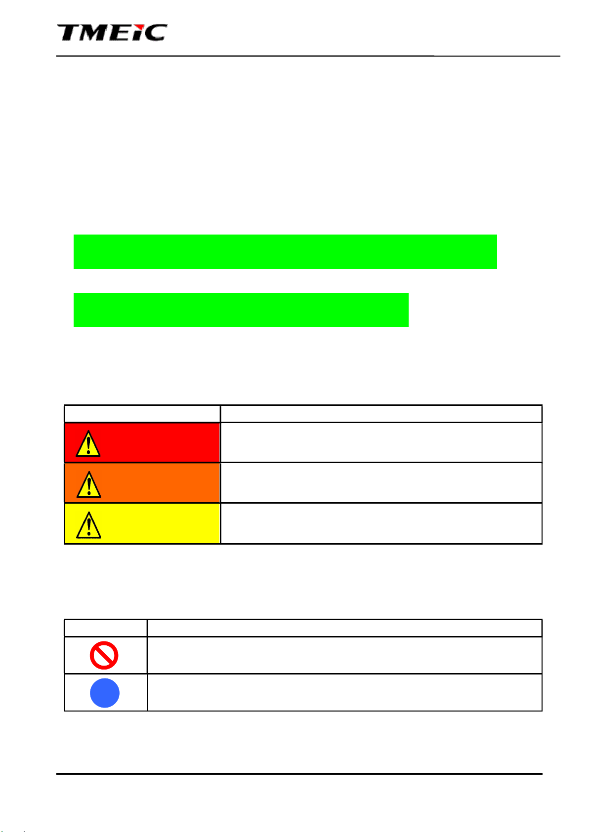
■ Explanation of markings
Marking Meaning of marking
Indicates that improper use or handling will result in death or serious
injury.
Indicates that improper use or handling may lead to death or serious
injury.
Indicates that improper use or handling may lead to injury to persons(*1)
or may cause damage to property(*2).
(*1): “injury to persons” refer to injuries, burns, electric shocks and other injuries that will not require hospitalization
or long periods of medical treatment.
(*2): “damage to property” refers to a wide-range of damage to assets and materials.
■ Meaning of symbols
Symbol Meaning of symbol
Indicates that the operation is prohibited
What is prohibited will be described in or near the symbol in either text or picture form.
Indicates mandatory action
What is mandatory will be described in or near the symbol in either text or picture form.
DANGER
WARNING
!
CAUTION

4GBG1009
PVU-L0800GR / PVU-L0840GR / PVU-L0880GR Installation Manual
2
■ Markings on this product
Symbol Meaning of symbol
AC voltage / current
DC voltage / current
DC positive voltage
DC Negative voltage
Earth ground
Caution, risk of electric shock
Warning for dangerous voltage
Caution, risk of electric shock
Energy storage timed discharge
Caution, risk of danger
Caution, hot surface
Refer to the operating instructions
4GBG1009
PVU-L0800GR / PVU-L0840GR / PVU-L0880GR Installation Manual
3
1.2. Limitation of use, disclaimer and disposal
■ Limitation of use
■ Disclaimer
■ Disposal
TMEIC assumes no responsibility in the following cases.
・ Accidents or damages that are caused by nature (i.e. earthquake, fire, lightening, flood, etc),
unauthorized third party, and/or deliberate or unintentional misuse.
・ Damage or losses accompanied with the operation or non-operation of this product (e.g. loss of
profit, halted business, etc).
・ Damage caused by using this inverter in a different way as described in the instruction manual.
・ Damage caused by incorrect operation of or in combination with equipment procured outside of
TMEIC’s responsibilities.
Disposal of this inverter or any of its components shall be done by a specialist in industrial waste
disposal. Improper disposal may result in explosion or generation of noxious gases, resulting in injury.
Additionally, local regulations regarding disposal of industrial equipment shall be observed.
TMEIC assumes no responsibility for any damage due to improper disposal or any other improper
use.
This product is intended to be used as a grid-connected inverter for photovoltaic generation. Any
other use is prohibited.
Make sure to consult with TMEIC in case a change in system specifications occurs (e.g. changes in
related equipment or other circumstances that may require adjustments to be made to the entire
system).

4GBG1009
PVU-L0800GR / PVU-L0840GR / PVU-L0880GR Installation Manual
4
2. Safety Precautions
2.1. Installation environment
■ Do not install the inverter where flammable or explosive gases are present
There is a risk of explosion and/or fire due to sparks that could be generated from
circuit breakers or contactors.
■ Provide enough space(※) for operation and maintenance when installing the
inverter
Sufficient clearance is required for maintenance space. It also assures sufficient air
flow, and could cause damage or fire due to over temperature if the clearance
space is reduced.
※Refer to “Installation clearance” in section 5.2 for details.
■ Do not install the inverter in locations that are exposed to extreme
temperature/humidity variations
Extreme operating conditions and condensation may cause performance
degradation and/or equipment failure
Do not install the inverter in an environment outside of the following requirements.
Requirement of Installation Environment:
Ambient temperature: -25~50℃
Relative humidity: 5~95%
■ Do not install the inverter in places where it can be subjected to vibrations
(※1) or shocks (※2)
Vibrations or shocks may cause performance degradation and/or equipment
failure.
※1・※2:Refer to “Inverter installation environment” in section 5.1 for details
DANGER
CAUTION
Forbidden
Mandatory
Forbidden
Forbidden

4GBG1009
PVU-L0800GR / PVU-L0840GR / PVU-L0880GR Installation Manual
5
■ Do not install the inverter in places that are exposed to air containing salts,
corrosive gases (※) and/or vapor containing water or oil
If installed in places where one or more of the above elements is present,
contact failure in circuit breakers and switches may occur, and may lead to
performance degradation and/ or equipment failure.
※:Refer to “Inverter installation environment” in section 5.1 for details
■ Do not install the inverter in locations with considerable amount of fine
particles that may contain iron and/or organic compounds.
It may cause insulation failure, contact failure in circuit breakers and switches,
performance degradation and/or equipment failure.
■ Do not install the inverter in altitudes over 4000m. Over 2000m : derating
The withstand voltage is reduced at high altitudes and could lead to performance
degradation and/or equipment failure.
■ This inverter must not be used in residential areas
This inverter may cause interference with household appliances if used in
residential areas. Such use must be avoided unless the user takes full
responsibility and proper measures to prevent interference with radio and
television broadcast signals.
CAUTION
Forbidden
Forbidden
Forbidden
Forbidden
4GBG1009
PVU-L0800GR / PVU-L0840GR / PVU-L0880GR Installation Manual
6
2.2. Transportation
■ Do not apply a mechanical shock over 1.5G to the inverter
A shock over 1.5G may cause performance degradation and/or equipment
failure.
■ Do not expose the package frame to salt water or rain
Salt water and rain may enter the enclosure and cause performance degradation
and/or equipment failure.
■ Do not transport, move or place the inverter in the horizontal position
Heavy internal components such as transformers and reactors will be subjected
to forces that may damage the inverter
CAUTION
Forbidden
Mandatory
Forbidden

4GBG1009
PVU-L0800GR / PVU-L0840GR / PVU-L0880GR Installation Manual
7
2.3. Storage environment
■ Do not store the inverter in locations that are exposed to extreme
temperature/humidity variations
Extreme storage temperatures and condensation may cause performance
degradation and/or equipment failure.
Do not install the inverter in an environment outside of the following
requirements.
Requirement of Storage Environment:
Ambient temperature -35~50℃
Relative humidity less than 95% (No condensation)
■ The inverter must be stored indoors
The inverter shall not be stored outdoors and exposed to rain, wind and/or
condensation (produced by temperature variation) to prevent performance
degradation and/or equipment failure unless it has been fully assembled with its
input and output terminals sealed and roofs installed. Note that the inverter roof
is shipped separately from the main unit.
■ Do not store the inverter in locations with considerable amount of fine
particles that may contain iron and/or organic compounds
It may cause insulation failure, contact failure in circuit breakers and switches,
performance degradation and/or equipment failure.
■ Do not store the inverter in places where vibrations(※1) or mechanical
shocks(※2) may occur
Vibrations or shocks may cause system performance degradation and/or
equipment failure.
※1・※2:Refer to “Inverter installation environment” in section 5.1 for details
■ Do not store the inverter in places exposed to air containing salts,
corrosive gases (※3) and/or vapor containing water or oil
If stored in a place where one of the above elements is present, contact failure in
circuit breakers and switches may occur, and may lead to performance
degradation and/ or equipment failure.
※3:Refer to “Inverter installation environment” in section 5.1 for details
CAUTION
Forbidden
Mandatory
Forbidden
Forbidden
Forbidden

4GBG1009
PVU-L0800GR / PVU-L0840GR / PVU-L0880GR Installation Manual
8
2.4. Unpacking of the inverter
■ When opening the package, do not inflict direct mechanical shock or
vibration to the inverter
Vibrations or shocks may cause performance degradation and/or equipment
failure
2.5. Transportation after unpacking
■ Do not transport, move or place the inverter in the horizontal position
Heavy internal components such as transformers and reactors will be subjected
to forces that may damage the inverter
CAUTION
CAUTION
Forbidden
Forbidden
4GBG1009
PVU-L0800GR / PVU-L0840GR / PVU-L0880GR Installation Manual
9
2.6. Installation and wiring of the inverter
■ During installation, do not incline the inverter at angles more than 10°
If the inverter is inclined at angles more than 10°, it may fall causing injuries and/or
damage.
■ The inverter must be connected to ground
Ground the inverter through the terminal marked “Grounding Electrode Terminal”.
If not grounded, insulation degradation may cause current leakage and create a
risk of electric shock.
Ensure a ground resistance of less than 5Ω.
■ The input and output circuits are isolated from the enclosure. Is the responsibility of the
installer to provide for system grounding in case it is required by sections 690-40 and 690-42
of the National Electric Code, ANSI/NFPA 70.
■ The AC output is not connected to ground
Do not ground any AC conductor. If the inverter is connected to a wye connected transformer, do not
ground the neutral of the wye connection.
■ Wiring methods in accordance with the National Electrical Code, ANSI/NFPA 70 are to be used.
■ After completing the installation and wiring work, make sure that all
protective covers are put in place
There is a risk of electric shock and injury if protective covers are not installed.
DANGER
Forbidden
Grounding Electrode
Terminal
Mandatory

4GBG1009
PVU-L0800GR / PVU-L0840GR / PVU-L0880GR Installation Manual
10
■ When performing installation and wiring work, install the roofs of the
inverter before the unit is exposed to external weather conditions to prevent
dust and/or water from entering. Roofs are shipped separately from the
inverter.
Dust and/or water inside the inverter may cause failure in the insulation and
contact failure in switches and circuit breakers, causing performance degradation
and/or equipment failure.
■ When performing installation, wiring, maintenance work, be careful not to
damage fragile parts (louvers, glass window, etc.).
■ Do not sit on, climb on or step on the ceiling
The enclosure can be damaged creating a risk of electric shock due to
reduction in internal clearance.
■ Do not perform installation and wiring work in locations with considerable
amount of fine particles that may include iron and/or organic compounds
It may cause insulation failure, contact failure in circuit breakers and switches,
performance degradation and/or equipment failure.
■ Do not perform installation and wiring work in places exposed to air
containing salts, corrosive gases (※) and/or vapor or oil steam
If performed in a place where one of the above elements is present, contact
failure in circuit breakers and switches may occur, and may lead to performance
degradation and/ or equipment failure.
※:Refer to “Inverter installation environment” in section 5.1 for details
Forbidden
Forbidden
CAUTION
Mandatory
Forbidden
Mandatory

4GBG1009
PVU-L0800GR / PVU-L0840GR / PVU-L0880GR Installation Manual
11
3. Index
1. About this manual ...............................................................................................................................................1
1.1. Explanation of markings and symbols .........................................................................................................1
1.2. Limitation of use, disclaimer and disposal ...................................................................................................3
2. Safety Precautions ..............................................................................................................................................4
2.1. Installation environment ...............................................................................................................................4
2.2. Transportation ..............................................................................................................................................6
2.3. Storage environment ....................................................................................................................................7
2.4. Unpacking of the inverter .............................................................................................................................8
2.5. Transportation after unpacking ....................................................................................................................8
2.6. Installation and wiring of the inverter ...........................................................................................................9
3. Index ................................................................................................................................................................ 11
4. Tools, Machinery and Materials Required for Installation and Wiring ............................................................. 12
5. Installation Environment .................................................................................................................................. 13
5.1. Inverter installation environment ............................................................................................................... 14
5.2. Installation clearance ................................................................................................................................ 15
5.3. Electrical Requirements ............................................................................................................................ 16
6. Structure and Outline of the Inverter ............................................................................................................... 17
7. Inverter Transportation .................................................................................................................................... 18
8. Storage ............................................................................................................................................................ 19
9. Unpacking ........................................................................................................................................................ 20
9.1. Package outline ........................................................................................................................................ 20
9.2. Main contents of the package ................................................................................................................... 21
9.3. Unpacking location .................................................................................................................................... 21
9.4. Guidelines for unpacking .......................................................................................................................... 21
9.5. Guidelines after unpacking ....................................................................................................................... 22
9.6. Transportation after unpacking ................................................................................................................. 23
10. Inverter Installation ........................................................................................................................................ 24
10.1. Cabinet base and tolerance for the skid ................................................................................................. 24
11. Fixation of the Inverter ................................................................................................................................... 25
11.1. Hardware for inverter fixation .................................................................................................................. 25
12. Base cover Installation................................................................................................................................... 26
13. Wiring and Connection .................................................................................................................................. 27
13.1. Torque value and check mark ................................................................................................................. 27
13.2. Connection of external cables and wires ................................................................................................ 29
13.3. Connection of the grounding electrode conductor and equipment grounding conductors ..................... 34
13.4. Connection of Input/output relay signals ................................................................................................. 36
13.5. Connection of Communication signals.................................................................................................... 37
14. Cleaning of the inside of the inverter and its surroundings ........................................................................... 38
15. Inspection after installation and wiring work .................................................................................................. 38
16. Inverter Specifications ................................................................................................................................... 39
17. Contact .......................................................................................................................................................... 42
4GBG1009
PVU-L0800GR / PVU-L0840GR / PVU-L0880GR Installation Manual
12
4. Tools, Machinery and Materials Required for Installation and Wiring
(1) Machinery and materials for handling cargo
Overhead Crane, Truck-Mounted Crane, Forklift, etc
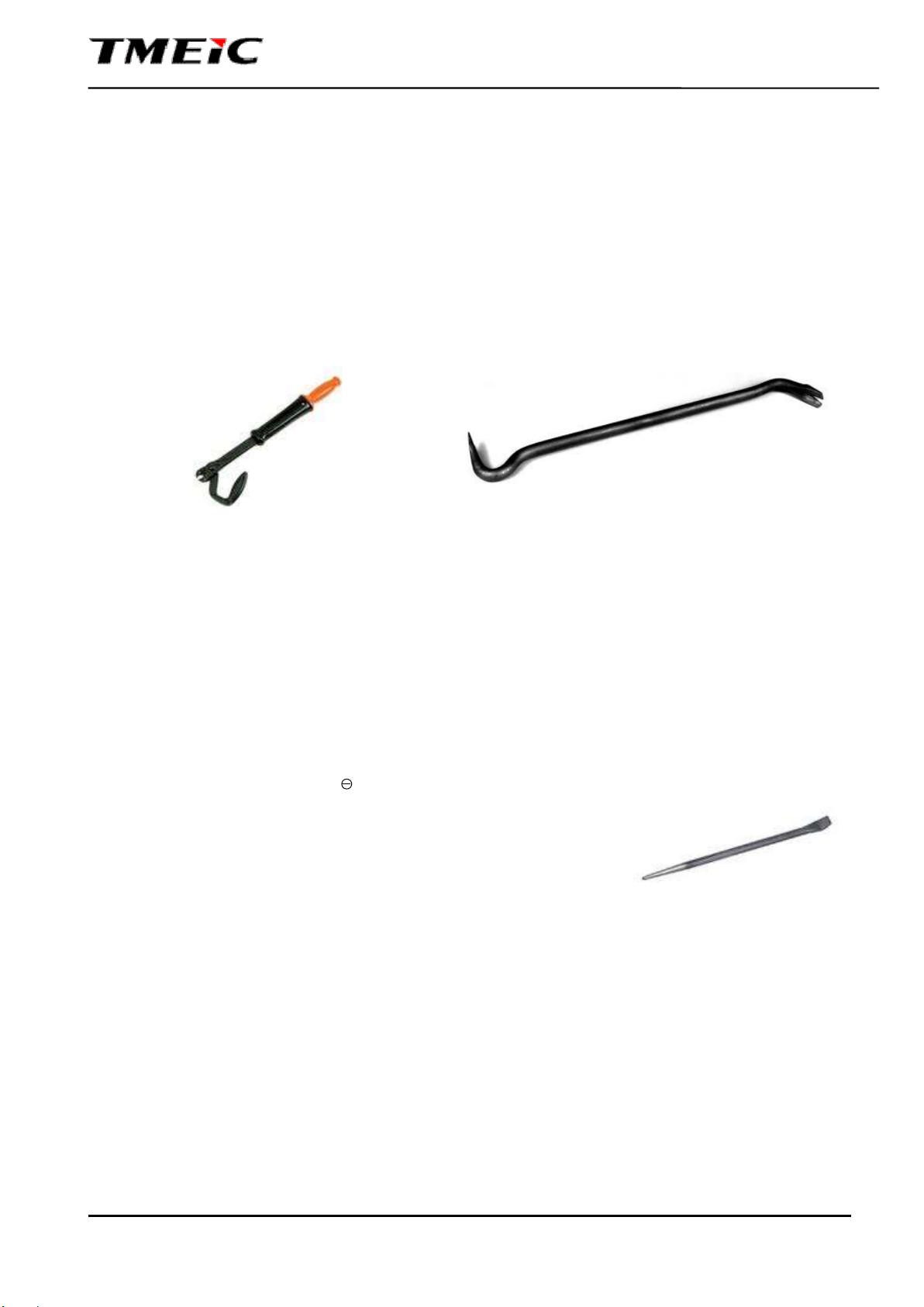
(2) Machinery and materials for opening the packing
① Nail Extractor Tool(Fig. 4.1、4.2)
② Hammer
③ Cutter/knife
④ Spanner/wrench
⑤ Other tools for uncrating
(3) Tools for Installation and Wiring
① Screwdriver ( ) ※Impact drivers are not allowed.
② Spanner/wrench (for M8、M10、M12、M16)
③ Socket Wrench (for M8、M10、M12、M16)
④ Torque Wrench (for M8, M10, M12、M16)
⑤ Pinch Bar (Fig. 4.3)
⑥ Permanent Maker (Red)
⑦ Other tools for wiring
Fig. 4.2 Crowbar
Fig. 4.1 Nail Puller
Fig. 4.3 Pinch Bar
Approx. 300mm
4GBG1009
PVU-L0800GR / PVU-L0840GR / PVU-L0880GR Installation Manual
13
5. Installation Environment
DANGER
■ Do not install the inverter where flammable or explosive gases are present
There is a risk of explosion and/or fire due to sparks that could be generated from
the circuit breakers or contactors
CAUTION
■ Do not install the inverter in locations that are exposed to extreme
temperature/humidity variations
Extreme operating conditions and condensation may cause performance
degradation and/or equipment failure.
Do not install the inverter in an environment outside of the following requirements.
The installation of a ventilation or air conditioning system will be required if the
recommended environmental conditions cannot be met.
Environmental Conditions:
Ambient temperature -25~50°C
Relative humidity 5~95% (No condensation)
■ Do not install the inverter in places where it can be subjected to vibrations
(※1) or shocks (※2)
Vibrations or shocks may cause performance degradation and/or equipment failure.
※1・※2:Refer to “Inverter installation environment” in section 5.1 for details
■ Do not install the inverter in places exposed to air containing salts, corrosive
gases (※) and/or vapor containing water or oil
If installed in a place where one of the above elements is present, contact failure in
circuit breakers and switches may occur, and may lead to performance degradation
and/ or equipment failure.
※:Refer to “Inverter installation environment” in section 5.1 for details
■ Do not install the inverter in locations with considerable amount of fine
particles that include iron and/or organic compounds
It may cause insulation failure, contact failure in circuit breakers and switches,
performance degradation and/or equipment failure.
■ Do not install the inverter in altitudes over 4000m. Over 2000m : derating
The withstand voltage is reduced at high altitudes and could lead to performance
degradation and/or equipment failure.
4GBG1009
PVU-L0800GR / PVU-L0840GR / PVU-L0880GR Installation Manual
14
5.1. Inverter installation environment
Inverter and related equipment should be installed according to the installation environment standard
detailed in Table 5.1
Not adhering to this standard may result in degradation of insulation and other effects leading to
reduction in lifetime and/or equipment failure.
It is recommended to measure and evaluate environmental conditions at the installation location prior
to inverter installation. In case there are parameters that do not comply with the specifications,
corrective measures should be taken prior to inverter installation.
Mandatory
■ When cleaning the area where the inverter is installed, use an electrical vacuum cleaner to
prevent rubbish and dust from getting into the air.
■ Do not use silicon type wax on the floor or other places adjacent to the inverter.
Table 5.1 Installation environment
No.
Item Installation Standard
1 Ambient Temperature Minimum and maximum temperature: -25°C to 50°C
Average over a 24 hour period should be between 5°C and 35°C
2 Relative Humidity Relative Humidity: 5 to 95%
Variation of temperature should not cause condensation.
3 Altitude Maximum altitude: 4000m above sea level. Over 2000m: derating
4 Atmospheric Pressure 860 to 1060hPa
5 Vibration and
mechanical shocks
Vibrations in the installation location should have a frequency less than 10Hz
or over 20Hz.
For frequencies below 10Hz, the acceleration should be less than 0.5G.
For frequencies over 20Hz and below 50Hz, the acceleration should be less
than 0.5G.
For frequencies over 50Hz and below 100Hz, the total amplitude of the
vibration should be less than 0.1mm.
6 Fine particles The air quality, where the inverter is installed, should be kept at the standard
dust levels, especially free of iron particles, oil, and organic compounds.
7
Corrosion Factor
*According to IEC-
654-4
(1987) Class 1
Average [PPM] Maximum [PPM]
Hydrogen Sulfide (H2S) <0.003 <0.01
Sulfur Dioxide (SO2) <0.01 <0.03
Chlorine Gas (Cl2)
(Relative Humidity >50%) <0.0005 <0.001
Chlorine Gas (Cl2)
(Relative Humidity <50%) <0.002 <0.01
Hydrogen Fluoride (HF) <0.001 <0.005
Ammonia Gas (NH3) <1 <5
Nitrogen Oxide (NOX) <0.05 <0.1
Ozone (O3) <0.002 <0.005
!
4GBG1009
PVU-L0800GR / PVU-L0840GR / PVU-L0880GR Installation Manual
15
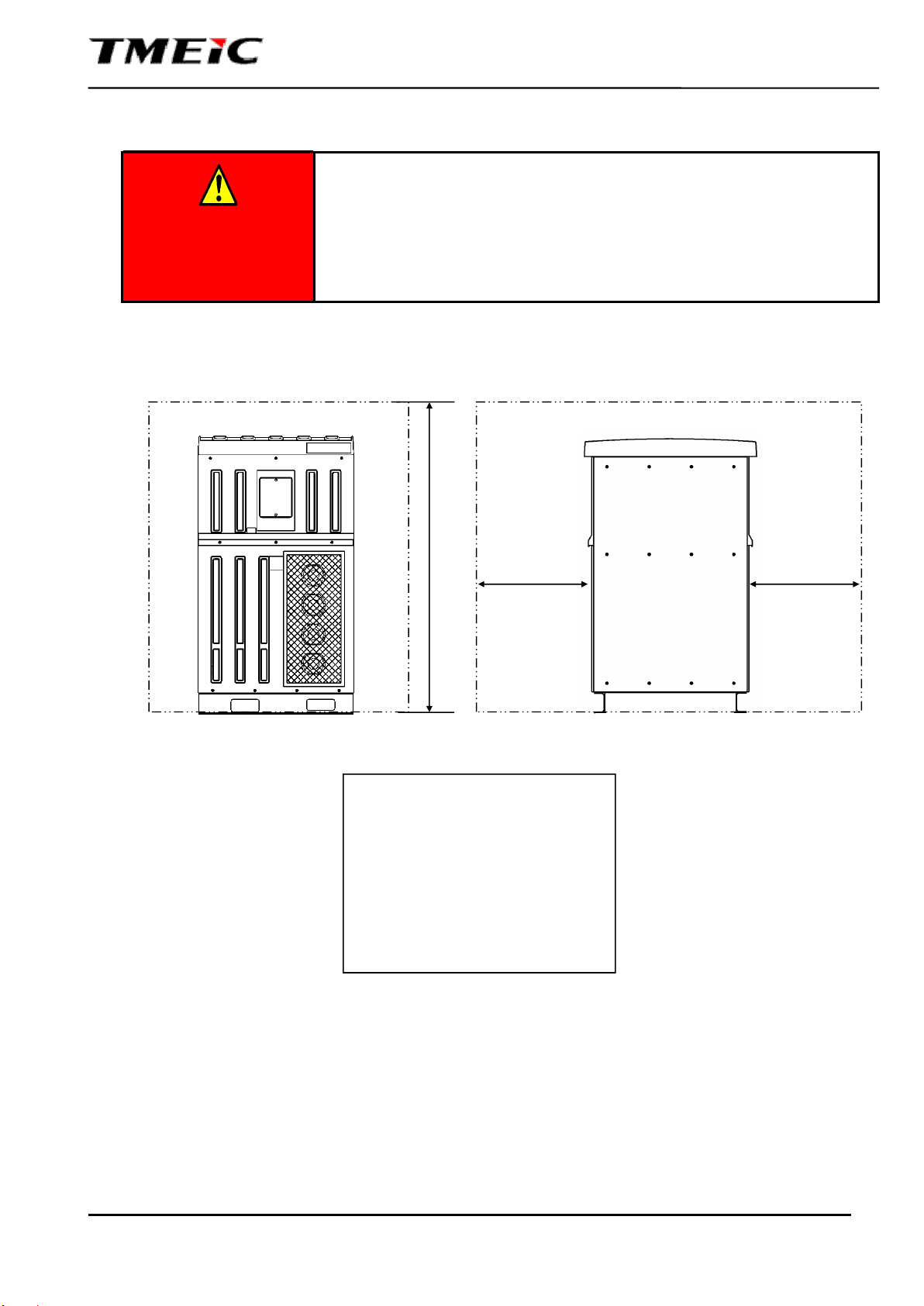
5.2. Installation clearance
DANGER
■ Provide enough space for operation and maintenance when installing
the inverter
Sufficient clearance is required for maintenance space. It also assures
sufficient air flow, and could cause damage or fire due to over temperature
if the clearance space is reduced.
Provide the following clearance for maintenance.
Note that the required maintenance space may change due to applicable standards or local
regulations enforced in the region where the inverter is installed.
Fig. 5.1 Inverter Installation Clearance
1500mm
(60 in)
1500mm
(60 in)
3500mm (138 in)
Refer to NEC/NFPA70 and local
regulations for required clearance in
front of the inverter. Clearance will
change if there are other electrical
equipment placed in front of the
inverter.
Front Side View Right Side View

4GBG1009
PVU-L0800GR / PVU-L0840GR / PVU-L0880GR Installation Manual
16
5.3. Electrical Requirements
(1) Grid Connection Step-up Transformer
Minimum requirements for a two-winding grid connection transformer are as follows:
- Galvanic isolation between windings is required.
- Only delta and ungrounded wye connections are allowed for the secondary (inverter side).
- The secondary winding (inverter side) should not be grounded at any point. Impedance grounding is also
not allowed.
- Shield between high voltage winding and low voltage winding is required. Shield should be connected to
the protective earth (PE) of the transformer.
- Impedance between primary and secondary should be more than 3% and less than 7%.
- When the dc circuit is grounded intentionally or accidentally, the phase to ground voltage of the
secondary may have a peak up to 110% the maximum dc input voltage (1500V).
- The transformer should be rated more than the capacity of the Inverters connected at secondary side.
- Other requirements may apply. Ask your TMEIC representative for further transformer requirements.
Fig. 5.2 Grid-connection step-up transformer
Inverter Grid
Transformer
Primary
Secondary

4GBG1009
PVU-L0800GR / PVU-L0840GR / PVU-L0880GR Installation Manual
17
6. Structure and Outline of the Inverter
Fig. 6.1 Inverter layout
Front View
Left Side View Right Side View
Cooling fans
Fork Pockets
LED Display
unit
Rear View

4GBG1009
PVU-L0800GR / PVU-L0840GR / PVU-L0880GR Installation Manual
18
7. Inverter Transportation
CAUTION
■ Do not apply a mechanical shock over 1.5G to the inverter
A shock over 1.5G may cause performance degradation or equipment
failure.
■ Do not expose the package frame to salt water or rain
Salt water and rain may enter the enclosure and cause performance
degradation and/or equipment failure.
The package frame provides good protection for the inverter during transportation. However, observe
the following precautions
(1) Do not apply an impact or shock to the package of over 1.5G.
(2) Do not expose the package to salt water or rain.
4GBG1009
PVU-L0800GR / PVU-L0840GR / PVU-L0880GR Installation Manual
19
8. Storage
■ Do not store the inverter in locations that are exposed to extreme
temperature/humidity variations
Extreme storage temperatures and condensation may cause performance degradation
and/or equipment failure.
Storage environment:
Ambient temperature -35~50℃
Relative humidity less than 95% (No condensation)
■ The inverter must be stored indoors
The inverter shall not be stored outdoors and exposed to
rain, wind and/or condensation
(produced by temperature variation) to prevent performance degradation and/or failure.
This applies even considering that the inverter is outdoor rated
■ Do not store the inverter in locations with considerable amount of fine particles
that may contain iron and/or organic compounds
It may cause insulation failure, contact failure in circuit breakers
and switches,
performance degradation and/or failure.
■ Do not store the inverter in places where vibrations( ※1) or mechanical
shocks(※2) may occur
Vibrations or shocks may cause performance degradation and/or failure.
※1・※2:Refer to “Inverter installation environment” in section 5.1 for details
■ Do not store the inverter in places exposed to air containing salts, corrosive
gases (※3) and/or vapor containing water or oil
If stored in a place where one of the above elements is present, contact failure in
circuit
breakers and switches may occur, and may lead to
performance degradation and/ or
failure.
※3:Refer to “Inverter installation environment” in section 5.1 for details
■ When storing the inverter before/after installation for a prolonged period of time,
protect the inverter from humidity
In case the inverter
is not protected from humidity, rust may appear in components and
may cause performance degradation and/or failure. Repair work would be required.
Take one of the following protective measures against humidity
(1) Place desiccant inside the cabinet (Refer to the table below).
(2) Reduce the humidity inside the cabinet using a space heater or a similar device.
(3) Reduce the humidity inside the cabinet by periodically operating the inverter under
no-load conditions.
CAUTION
Storage time and amount of desiccant
No.
Storage time Silica Gel Activated Carbon
1 3 ~ 6 Months 500g/m3(※4) Not required
2 6 Month ~ 1 year 700 g/m3 700 g/m3
3 Over 1 year Change/supply desiccant according to No.1 or No.2
※4:(g/m3)indicates the amount of desiccant per 1m3 of cabinet volume
※5:After placing the desiccant inside, seal the cabinet with a shrink wrap
This manual suits for next models
2
Table of contents
Other TMEIC Inverter manuals


