SKF TIH 100m User manual

Instructions for use
Mode d’emploi
Bedienungsanleitung
Instrucciones de uso
Manuale d’istruzioni
Instruções de uso
使用说明书
Инструкция по эксплуатации
Betjeningsvejledning
SKF TIH 030m


English 2
Français 14
Deutsch 26
Español 38
Italiano 50
Português 62
中文74
Русский 86
English Français Deutsch Español Italiano Português 中文Русский Dansk
Dansk 98

2SKF TIH 030m
EC Declaration of conformity ....................................................................................3
Safety recommendations..........................................................................................4
1. Introduction ....................................................................................................5
1.1 Intended use .................................................................................................................. 5
1.2 Principle of operation ................................................................................................... 5
1.3 Distinguishing features ................................................................................................ 6
2. Description ......................................................................................................6
2.1 Components .................................................................................................................. 6
2.2 Technical data ................................................................................................................ 7
3. Installation of mains plug ................................................................................8
4. Preparation for use .........................................................................................8
5. Operation ........................................................................................................9
5.1 Function of displays ...................................................................................................... 9
5.2 Function of buttons ...................................................................................................... 9
5.3 Temp mode .................................................................................................................... 9
5.4 Time mode ..................................................................................................................10
5.5 Temperature measurement ......................................................................................10
5.6 Change of temperature unit ......................................................................................10
5.7 Demagnetisation .........................................................................................................11
5.8 Power level selection ..................................................................................................11
6. Safety features ..............................................................................................12
7. Troubleshooting ............................................................................................12
8. Spare parts ...................................................................................................13
Table of contents
Original instructions

3SKF TIH 030m
English
EC Declaration of conformity
We,
SKF Maintenance Products
Kelvinbaan 16
3439 MT Nieuwegein
The Netherlands
herewith declare that the following product:
SKF Small Induction Heater
TIH 030m
has been designed and manufactured in accordance with:
EUROPEAN LOW VOLTAGE DIRECTIVE 2014/35/EU
EMC DIRECTIVE 2014/30/EU as outlined in the harmonized norm for
EN61000-6-3:2007 /A1:2011
EN61000-6-2:2005
EN61000-4-2
EN61000-4-3
EN61000-4-4
EN61000-4-5
EN61000-4-6
EN61000-4-8
EN61000-4-11
EUROPEAN ROHS DIRECTIVE 2011/65/EU
Nieuwegein, The Netherlands,
May 2016
Sébastien David
Manager Product Development and Quality

4SKF TIH 030m
Safety recommendations
• Because the TIH 030m generates a magnetic field, people wearing
a pacemaker must not be within 5 m (16 ft) of the TIH 030m during
operation. Electronic equipment, such as wristwatches, may also
be affected.
• During the heating process observe a safety distance of 50 cm (1.6 ft) with
the workpiece, the heater coil or the core.
• Follow the operating instructions at all times.
• Be certain that the voltage supply is correct.
• Electrical arcing may occur when a potential difference exists between the
TIH 030m and the workpiece. This is not dangerous to human beings and
will not cause damage to the TIH 030m or the workpiece. However, the
TIH 030m must never be used in areas where there is a risk of explosion.
• Do not expose the TIH 030m to high humidity.
• Never operate the TIH 030m without a yoke in position.
• Never operate the TIH 030m with the cable of the remote control between
the vertical supports of the yoke.
• Do not modify the TIH 030m.
• Use proper handling equipment when lifting heavy workpieces.
• Avoid contact with hot workpieces. Wear the supplied heat resistant gloves
to handle hot workpieces.

5SKF TIH 030m
English
1. Introduction
The SKF TIH 030m induction heater is designed to heat bearings that are mounted with an
interference fit onto a shaft. The heat causes the bearing to expand, which eliminates the
need to use force during installation. A 90 °C (162 °F) temperature difference between the
bearing and shaft is generally sufficient to enable installation. At an ambient temperature
of 20 °C (68 °F), the bearing must therefore be heated to 110 °C (230 °F).
1.1 Intended use
The TIH 030m has been designed to heat rolling bearings. However, other
metalworkpieces that form a closed circuit can also be heated. Examples of acceptable
workpieces include bushings, shrink rings, pulleys, and gears. All bearings that fit over the
inductive coil and between the vertical supports with the top yoke in place can be heated
using the TIH 030m. In addition, smaller bearings can be placed over any of the three
standard yokes. See the illustrations at the beginning of this manual for examples.
1.2 Principle of operation
The TIH 030m generates heat by means of a large
electrical current that is magnetically induced in the
workpiece by a coil within the heater.
The high voltage, low current electricity flowing
through the large number of windings in the
inductive coil induces low voltage, high current
electricity in the workpiece. Because the workpiece
has the electrical characteristics of a coil with a
single, short-circuited winding, the high current
generates heat within the workpiece.
Because the heat is generated within the workpiece,
all of the heater components remain cool.

6SKF TIH 030m
1.3 Distinguishing features
• Remote control panel
To improve the ease of use and to diminish the risk of contact with the hot
bearing during operation, the TIH 030m heater is supplied with a remote control
panel which can be detached from the heater.
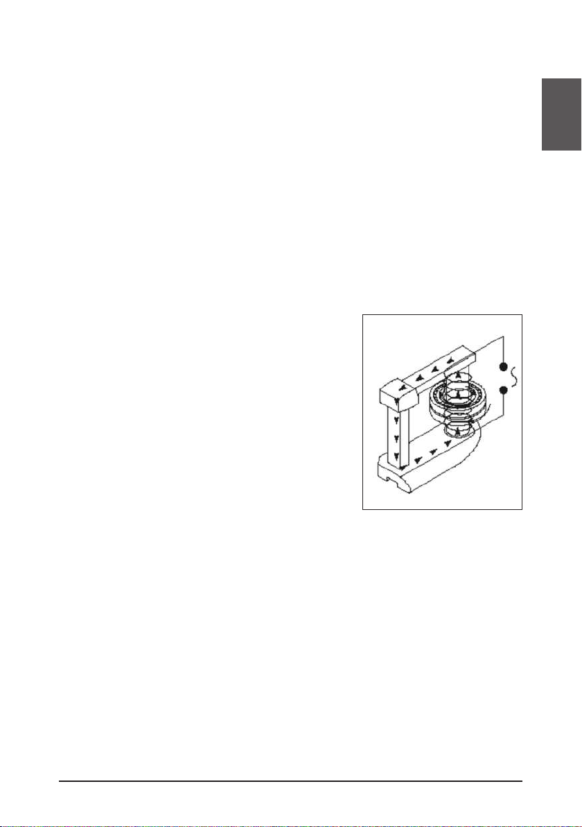
• Inductive coil
When heated the workpiece is located at the same position on the core as the
inductive coil. This design improves efficiency, resulting in less power consumption
and faster heating, which reduce the cost to heat each bearing.
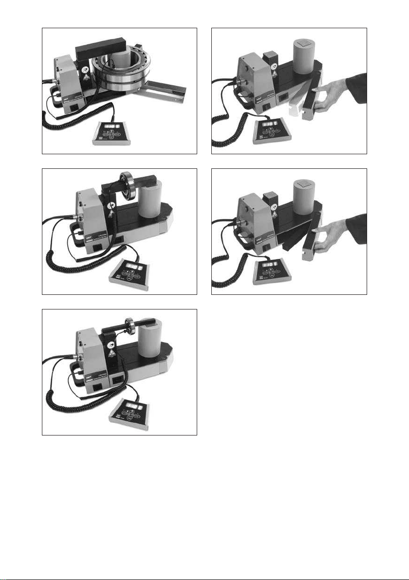
• Folding bearing supports
To support large bearing positioned around the inductive coil the TIH 030m induction
heater is fitted with folding bearing supports. See the illustrations at the beginning of
this manual.
• Yoke storage
All three yokes can be stored inside the heater. Two yoke storage are located
behind the folding bearing supports. Storage of the small and medium yokes is
in the yoke storage at the heater circuit breaker side.
Storage of the large yoke is in the yoke storage at the heater mains cable side.
See the illustrations at the beginning of this manual.
2. Description
The operation of the heater is controlled by the internal electronics in either of two modes.
The operator can either select the desired temperature of the bearing in
TEMP MODE or set the length of time that the bearing will be heated in TIME MODE.
The power level can be adjusted to 100% or 50% for slower heating of sensitive workpieces
(for example, bearings with C1 or C2 clearance).
2.1 Components
The TIH 030m induction heater contains a U-shaped iron core with an inductive coil
surrounding one of the vertical supports. A detachable remote control panel is included.
The remote control electronics and the internal electronics control the operation of the
heater. A removable yoke on the top of the vertical supports allows the workpiece to be
placed onto the heater. To accommodate smaller workpieces, two smaller yokes are also
provided. A temperature probe is also included with the heater. Heat-resistant gloves are
also included.

7SKF TIH 030m
English
2.2 Technical data
TIH 030m
Voltage (± 10%) 230 V / 50 - 60 Hz or 110 V / 50 - 60 Hz
Recommended line protection 10 A fuse rating for 230 V
20 A fuse rating for 110 V
Power consumption (maximum) 2,0 kVA
Temperature control 0 - 250 °C (32 - 482 °F); in steps of 1°
Probe type Thermocouple, K type
Probe maximum temperature 250 °C (482 °F)
Time mode 0-60 minutes; in steps of 0,1 minute
Power range 100% - 50%
Demagnetization automatic; residual magnetism <2A/cm
Overall dimensions (w x d x h) 460 x 200 x 260 mm (18.1 x 7.9 x 10.2 in)
Area between supports (w x h) 100 x 135 mm (3.9 x 5.3 in)
Coil diameter 95 mm (3.7 in)
For minimum bearing bore diameter of
100 mm (3.9 in)
Weight (with yokes) 20,9 kg (46.0 lbs)
Workpiece maximum weight bearing: 40 kg (88 lbs);
solid component: 20 kg (44 lbs)
Maximum heating temperature approx. 250 °C (482 °F)
Depending on bearing or workpiece weight.
For higher temperatures, please contact SKF.
m20* 28 kg (bearing 23136)
Standard yoke dimensions: For minimum bearing bore diameter of:
45 x 45 x 215 mm (1.7 x 1.7 x 8.4 in) 65 mm (2.6 in)
28 x 28 x 215 mm (1.1 x 1.1 x 8.4 in) 40 mm (1.6 in)
14 x 14 x 215 mm (0.6 x 0.6 x 8.4 in) 20 mm (0.8 in)
*m20 represents the weight (kg) of the heaviest SRB 231 bearing that can be heated from
20 to 110 °C (68 to 230 °F) in 20 minutes.

8SKF TIH 030m
3. Installation of mains plug
A qualified electrician must install a suitable mains plug. The correct supply voltage is
shown in section 2.2.
The wires should be connected as follows:
TIH 030m/230V, TIH 030m/110V
Colour of TIH 030m wire Mains supply terminal
yellow / green ground
blue neutral
brown phase 1
Verify that the correct fuse is installed. See section 2.2 for fuse rating specifications.
4. Preparation for use
• Place the TIH 030m in the horizontal position on a stable surface.
• Connect the mains plug to a suitable mains supply.
• Plug the remote control into the connector on the carrying handle side of the heater.
• For workpieces with an internal diameter large enough to fit over the inductive coil,
follow these steps:
- Place the workpiece over the inductive coil using appropriate lifting equipment.
- For best performance, adjust the position of the workpiece so that the
inductive coil is in the centre.
- Position the largest yoke so that it completely covers the top of both vertical
supports.
• For workpieces that do not fit over the inductive coil, follow these steps:
- Choose the largest of the three yokes that fit through the internal diameter
of the workpiece.
- If necessary, remove the top yoke from the TIH 030m.
- Slide the workpiece onto the yoke that you have selected.
- Position the yoke on the TIH 030m with the bright underside resting evenly
on the two vertical supports.
• If you will use TEMP MODE, plug the temperature probe into the connector on the
carrying handle side of the heater. Place the magnetic end of the probe on the inner
ring of the bearing or on the innermost surface of the workpiece.
• Switch on the TIH 030m.
• Observe the self-test of the remote control display and signal tone.

9SKF TIH 030m
English
5. Operation
5.1 Function of displays
• The remote control display shows the selected
time or temperature for heating.
• The power LED’s show the selected power
setting.
Display Indication
t time in minutes
°C temperature in degrees Celcius
°F temperature in degrees Fahrenheit
5.2 Function of buttons
Button Function
POWER Press to adjust the power
The selected power is indicated with an LED
MODE Press to switch between TIME MODE and TEMP MODE
UP (+) Press to increase the value shown on the remote control display
DOWN (-) Press to decrease the value shown on the remote control display
START / STOP Press to start or stop the heater
The LED on the START / STOP button is lit when the heater is heating
and flashes during temperature measurement
5.3 Temp mode
• If the remote control display shows ‘t’, press MODE to select TEMP MODE.
The remote control display shows °C or °F in TEMP MODE.
• The selected temperature is shown on the remote control display.
The default temperature for bearings is 110 °C (230 °F). If a different temperature
is desired, press UP or DOWN to adjust the temperature in steps of 1°.
• It may be desirable to heat bearings to temperatures above 110 °C (230 °F) for
increased mounting time. Consult the SKF bearing specifications to determine the
maximum permitted temperature. Always ensure the bearing does not lock due to an
excessive expansion of the inner ring compared to outer ring. See section 5.8.
• If needed press POWER to select the power level. Use the guidelines in section 5.8 to
determine the correct power setting.
• Make sure the temperature probe is mounted on the bearing inner ring.
• Press START / STOP to start the heater. The remote control display shows the current
temperature of the workpiece.

10 SKF TIH 030m
• During heating the selected temperature can be displayed for 1 second
by pressing MODE.
• When the selected temperature has been reached, the heater demagnetises the
workpiece, switches off, and generates an acoustic signal for 10 seconds or until
START / STOP is pressed.
• Press START / STOP to stop the heater.
• Remove the workpiece with proper handling equipment.
• If the workpiece remains on the heater, the heater will start again when the
temperature of the workpiece drops 10 °C (18 °F). Press START / STOP to stop the
heater and demagnetise the workpiece.
• The TIH 030m is now ready to heat another workpiece with the same settings.
5.4 Time mode
• If the remote control display shows °C or °F, press MODE to select TIME MODE.
The remote control display shows ‘t’ in TIME MODE.
• Press UP or DOWN to adjust the time in steps of 0.1 minute.
• Press POWER to select the power level. Use the guidelines in section 5.8 to
determine the correct power setting.
• Press START / STOP to start the heater. The remote control display shows the time
that remains.
• During heating the temperature measured by the probe can be displayed for a couple
of seconds by pressing MODE.
• When the time has elapsed, the heater demagnetises the workpiece, switches off, and
generates an acoustic signal for 10 seconds.
• Press START / STOP to cancel the acoustic signal and stop the heater.
• Remove the workpiece with proper handling equipment.
• The TIH 030m is now ready to heat another workpiece with the same settings.
5.5 Temperature measurement
When the heater is not operating, the temperature of the workpiece can be measured by
pressing MODE and START / STOP at the same time.
The LED on the START / STOP button flashes during temperature measurement.
Press START / STOP to cancel temperature measurement.
5.6 Change of temperature unit
Press MODE and UP at the same time to switch between °C and °F.
The temperature unit setting remains the same even after disconnection from
mains power.

11SKF TIH 030m
English
5.7 Demagnetisation
The workpiece is automatically demagnetised when heating is complete.
Demagnetisation will not occur if the power is interrupted or the main switch is switched
off. To use the TIH 030m for demagnetisation only, select TIME MODE and set the time to
0.1 minute (6 seconds).
5.8 Power level selection
When heating bearings with an induction heater, most of the heat will be generated in the
inner bearing race. The heat will then be transferred through the bearing. It is therefore
important that bearings with small internal clearance or slight preload are heated slowly.
Slow heating ensures that the bearing expands evenly, thereby preventing damage to the
bearing.
The shape, weight, size, and internal clearances all affect the amount of time required to
heat a bearing. The large variety of bearing types precludes the possibility of providing a
specific power level setting for each type. Instead, the following guidelines are provided:
• For sensitive bearings (including bearings with C1 or C2 internal clearance) or
bearings with brass cages, do not exceed 50% power.
• When using the small yoke, never exceed 50% power.

12 SKF TIH 030m
6. Safety features
The TIH 030m is equipped with the following safety features:
• Automatic overheating protection
• Automatic current control
• Over-current circuit breaker.
• In the TEMP MODE the heater will switch off if the temperature probe does not
register a temperature increase of 1°C (1.8°F) every 15 seconds (0.25 minute).
To increase the interval to 30 seconds (0.50 minute), press MODE and DOWN at the
same time.
7. Troubleshooting
A system fault will be indicated by an acoustic signal and one of the following fault
codes on the remote control display:
Display Fault Action
E03 E Overheated coil Wait until the inductive coil cools
Switch the heater OFF and then back ON
E05 E Temperature increase of
less than 1°C (1.8°F)
every 15 seconds
(or 1° every 30 seconds)
Check the temperature probe connection
If the connection is OK, select the 30 second
interval as described in section 6 or operate
the heater in TIME MODE
E06 E Temperature probe not
connected (or defective)
or excessive temperature
drop
Check the temperature probe
E10E Electronics communication
problem Switch the heater OFF and then back ON
If problem remains return the TIH to SKF
for repair
E11E Electronics communication
problem Switch the heater OFF and then back ON
If problem remains return the TIH to SKF
for repair
E12E Electronics communication
problem Switch the heater OFF and then back ON
If problem remains return the TIH to SKF
for repair

13SKF TIH 030m
English
8. Spare parts
Designation Description
TIH 030-P230V Power print 230V - 200 - 240V, 50 - 60 Hz
TIH 030-P110V Power print 110V - 100 - 120V, 50 - 60 Hz
TIH 030-Y7 Yoke 45 x 45 x 215 mm
TIH 030-Y6 Yoke 40 x 40 x 215 mm
TIH 030-Y4 Yoke 28 x 28 x 215 mm
TIH 030-Y3 Yoke 20 x 20 x 215 mm
TIH 030-Y2 Yoke 14 x 14 x 215 mm
TIH 030-YS Support yoke set - 45 x 45 x 100 mm (2x)
TIH CP Control print
TIH RC Remote control
TIH CB10A Circuit breaker 10A for TIH 030M/230V
TIH CB20A Circuit breaker 20A for TIH 030M/110V
TIH P20 Temperature probe K type incl. cable and plug

14 SKF TIH 030m
Déclaration de conformité UE.................................................................................15
Recommandations de sécurité................................................................................16
1. Introduction ..................................................................................................17
1.1 Utilisation prévue ........................................................................................................17
1.2 Principe de fonctionnement ......................................................................................17
1.3 Caractéristiques distinctives ......................................................................................18
2. Description ....................................................................................................18
2.1 Composants .................................................................................................................18
2.2 Caractéristiques techniques ......................................................................................19
3. Installation de la prise secteur .......................................................................20
4. Preparation pour utilisation ...........................................................................20
5. Fonctionnement ............................................................................................21
5.1 Fonction des écrans ....................................................................................................21
5.2 Fonction des boutons .................................................................................................21
5.3 Mode “ TEMP MODE” .................................................................................................21
5.4 Mode “TIME MODE” ...................................................................................................22
5.5 Mesure de la température..........................................................................................23
5.6 Modification de l’unité de mesure de la température.............................................23
5.7 Démagnétisation..........................................................................................................23
5.8 Sélection du niveau de puissance..............................................................................23
6. Dispositifs de sécurité ...................................................................................24
7. Dépannage ....................................................................................................24
8. Spare parts ...................................................................................................25
Table des matières
Traduction extraite du mode d’emploi d’origine

15SKF TIH 030m
Français
Déclaration de conformité CE
Nous,
SKF Maintenance Products
Kelvinbaan 16
3439 MT Nieuwegein
Pays-Bas
déclarons que le produit suivant:
Le Chauffage Par Induction SKF
TIH 030m
a été conçu et fabriqué conformément à
la DIRECTIVE EUROPÉENNE RELATIVE AUX BASSES TENSIONS 2014/35/EU
la EMC DIRECTIVE 2014/30/EU, telle qu’elle est décrite dans la norme
harmonisée pour
EN61000-6-3:2007 /A1:2011
EN61000-6-2:2005
EN61000-4-2
EN61000-4-3
EN61000-4-4
EN61000-4-5
EN61000-4-6
EN61000-4-8
EN61000-4-11
DIRECTIVE EUROPÉENNE ROHS 2011/65/UE
Nieuwegein, Pays-Bas,
Le 1 mai 2016
Sébastien David
Responsable Développement de Produits et Responsable Qualité

16 SKF TIH 030m
Recommandations de sécurité
• Comme l’appareil TIH 030m produit un champ magnétique, il est vivement
recommandé aux porteurs de stimulateur cardiaque de se
tenir à une distance minimale de 5 mètres du TIH 030 m pendant
le fonctionnement de l’appareil. Tous les appareils électroniques tels
que les montres-bracelets peuvent aussi être “déréglées” par ce
champ magnétique.
• Lors du processus de chauffage, restez à une distance de sécurité de
50 cm de la pièce à chauffer, de la bobine de chauffage et du noyau.
• Observez bien attentivement et à tout moment toutes les instructions
d’utilisation.
• Assurez-vous que la tension d’alimentation de l’appareil est correcte.
• Un arc électrique peut se produire lorsqu’il existe une différence de
potentiel entre le TIH 030m et la pièce à chauffer. Cet arc électrique
est inoffensif pour les êtres humains et n’endommage ni le TIH 030m
ni la pièce à chauffer. Ne jamais utiliser le TIH 030m dans des zones
comportant un risque d’explosion.
• L’appareil TIH 030m ne doit pas être exposé à une forte humidité.
• Ne jamais utiliser le TIH 030m sans barreau.
• Ne jamais utiliser le TIH 030m avec le câble de la télécommande entre les
supports verticaux du barreau.
• Ne jamais modifier le TIH 030m.
• Des outils de manutention adaptés doivent être utilisés pour soulever des
pièces lourdes.
• Il faut éviter tout contact avec les pièces chauffées.
Pour leur manipulation, équipez-vous de gants résistants à la chaleur.

17SKF TIH 030m
Français
1. Introduction
Le SKF TIH 030m est un appareil de chauffage par induction, conçu pour chauffer des
roulements montés avec un ajustement serré sur un arbre. La chaleur produite dilate le
roulement, et permet ainsi d’effectuer un montage sans endommager le roulment et sans
efforts. . Un écart de température de 90 °C entre le roulement et l’arbre est en général
suffisant pour le montage. À une température ambiante de 20 °C , le roulement doit donc
être chauffé à 110 °C .
1.1 Utilisation prévue
Le TIH 030m a été conçu pour chauffer les roulements. Mais toute autre pièce métallique
qui forme un circuit fermé peut également être chauffée. C’est le cas, par exemple, des
bagues de serrage, des poulies et des pignons et engrenages.
Tous les roulements montés sur la bobine à induction verticale et entre les supports
verticaux avec l’un des barreaux supérieur mis en place peuvent être chauffés grâce au
TIH 030m. De petits roulements peuvent en outre être placés sur l’un des trois barreaux
standards (on utilisera alors la fonction “réglage de puissance”).
Consultez les illustrations au début de ce manuel pour plus d’exemples.
1.2 Principe de fonctionnement
Le TIH 030m produit de la chaleur au moyen d’un
grand courant électrique magnétiquement induit
dans la pièce par une bobine placée à l’intérieur du
chauffage.
L’électricité à haute tension et à faible intensité qui
circule dans les nombreux enroulements de la bobine
à induction produit une électricité à basse tension et
de forte intensité dans la pièce à chauffer. La pièce à
chauffer ayant les caractéristiques électriques d’une
bobine avec un enroulement unique court-circuité, la
haute intensité produit de la chaleur dans la pièce.
La chaleur n’est donc produite qu’à l’intérieur de la
pièce, toutes les pièces de l’appareil restant froides.

18 SKF TIH 030m
1.3 Caractéristiques distinctives
• Télécommande
Pour faciliter davantage l’emploi et réduire le risque de contact avec le roulement
chaud pendant son fonctionnement, le chauffage TIH 030m est fourni avec une
télécommande que l’on peut détacher du chauffage.
• Bobine à induction
Lors de son chauffage, la pièce (d’un diamètre intérieur supérieur à 95 mm) doit
être placée sur le noyau dans la même position que la bobine à induction.
Ce montage améliore considérablement l’efficacité de l’appareil, permet de réaliser
des économies d’énergie et d’accélérer le processus de chauffage.
Tout ceci combiné, entraîne une réduction totale du coût de chauffage importante de
chaque pièce à chauffer.
• Supports de roulement pliants
Pour soutenir un grand roulement positionné autour de la bobine à induction, le
chauffage à induction TIH 030m est équipé de 2 bras supports de roulement pliants.
Voir les illustrations au début de ce manuel.
• Rangement des barreaux
Les trois barreaux (fournit en standard) doivent être rangés à l’intérieur du chauffage
afin d’éviter tout endommagement.. Deux espaces de rangement des barreaux se
trouvent derrière les bras supports de roulement pliants.
L’espace de rangement des barreaux petit et moyen se trouve dans l’espace de
rangement de barreaux du côté du disjoncteur de l’appareil de chauffage.
L’espace de rangement du grand barreau se trouve du côté du câble d’alimentation
secteur de l’appareil de chauffage. Voir les illustrations au début de ce manuel.
2. Description
Le fonctionnement du chauffage est commandé par le module de commande électronique,
et ce suivant deux modes de fonctionnement : L’utilisateur peut choisir de régler soit la
température du roulement souhaitée en TEMP MODE (mode température) soit de fixer la
durée pendant laquelle le roulement sera chauffé en TIME MODE
(mode durée). Le niveau de puissance peut être réglé à 100% ou 50 % pour le chauffage
plus lent de pièces sensibles (comme par exemple les petits roulements ou ceux à jeu
réduit de type C1 ou C2).
2.1 Composants
Le chauffage par induction TIH 030m contient un noyau en fer en U avec une bobine
à induction qui entoure l’un des supports verticaux. Une télécommande amovible est
incluse. L’électronique de la télécommande et l’électronique interne commandent le
fonctionnement de l’appareil de chauffage. Un barreau amovible dans la partie supérieure
des supports verticaux permet de venir placer la pièce sur l’appareil de chauffage.
Deux barreaux plus petits sont également fournis pour installer les pièces plus petites.
L’appareil est équipé d’une sonde de température.
Une paire de gants résistants à la chaleur (max 150°C) est livrée avec l’équipement.
Other manuals for TIH 100m
4
Table of contents
Languages:
Other SKF Power Tools manuals
Popular Power Tools manuals by other brands

Hyundai power products
Hyundai power products HCOMBI427 Original instructions

Milwaukee
Milwaukee M18 2626-20 Operator's manual

New World Technologies
New World Technologies E- ER 700 user manual

Luna
Luna 26202-0209 manual

Genesis
Genesis GMT15A Operator's manual

Porter-Cable
Porter-Cable 450 instruction manual