SmarTire Systems GENII User manual

SmarTire Systems Inc.
Tire Monitoring System Reference Manual
6/20/2000 Page 1of 56
This manual is under review by SmarTire –DO NOT ISSUE
Draft
Tire Monitor System Reference
Manual
GENII
Draft
Note; Prior to issue this manual to be examined and approved by;
Engineering
Marketing
Customer Service

SmarTire Systems Inc.
Tire Monitoring System Reference Manual
6/20/2000 Page 2of 56
This manual is under review by SmarTire –DO NOT ISSUE
Table of Contents
FCC Notice...................................................................................................................................5
Introduction.................................................................................................................................6
Purpose of Manual....................................................................................................................6
About Tire Monitoring Systems ..............................................................................................6
Feature Summary ..................................................................................................................................................................7
System Scope of Use and Warnings ........................................................................................ 8
The SmarTire™ System and Tire Maintenance..............................................................................................................8
System Installation and Usage............................................................................................................................................8
Use of Chemicals ..................................................................................................................................................................8
Power Connection.................................................................................................................................................................8
Warnings.................................................................................................................................................................................8
SmarTire Product Overview..................................................................................................10
Product List.............................................................................................................................10
Tire Monitor System Kit Component Table ........................................................................11
System Descriptions ................................................................................................................12
Pressure Alert Systems–2 and 4 wheels–Multi-fit Strap Mount Transmitters.....................................................12
Overview.........................................................................................................................................................................12
Bill of Materials .............................................................................................................................................................13
Component Images........................................................................................................................................................14
Pressure Alert Systems–2 and 4 wheels–Multi-fit Valve Mount Transmitters....................................................15
Overview.........................................................................................................................................................................15
Bill of Materials .............................................................................................................................................................16
Component Images........................................................................................................................................................17
Pressure Alert Full Function Display...............................................................................................................................18
Overview.........................................................................................................................................................................18
Bill of Materials .............................................................................................................................................................19
Component Images........................................................................................................................................................19
Pressure Alert Flexible Power Adaptor...........................................................................................................................20
Overview.........................................................................................................................................................................20
Bill of Materials .............................................................................................................................................................20
Component Image..........................................................................................................................................................20
Pressure Alert Transmitter Kit –2 -Multi-fit Strap Mount Transmitters .................................................................21
Overview.........................................................................................................................................................................21
Bill of Materials .............................................................................................................................................................21
Component Image..........................................................................................................................................................21
Pressure Alert Transmitter Kit–2 -Multi-fit Valve Mount Transmitters................................................................22
Overview.........................................................................................................................................................................22
Bill of Materials .............................................................................................................................................................22
Component Image..........................................................................................................................................................22
Pressure Alert Valve Kits ..................................................................................................................................................23
Overview.........................................................................................................................................................................23
Component Image..........................................................................................................................................................23
Receiver......................................................................................................................................24

SmarTire Systems Inc.
Tire Monitoring System Reference Manual
6/20/2000 Page 3of 56
This manual is under review by SmarTire –DO NOT ISSUE
Operation.................................................................................................................................24
Programming the Receiver....................................................................................................24
Multi-function Display (MFD)................................................................................................25
Controls and Display ..............................................................................................................25
ICON Summary Table ........................................................................................................... 26
Multi-function Display Operation Modes.............................................................................27
Mode Summary ...................................................................................................................................................................27
Stand-By mode....................................................................................................................................................................27
Power Stages........................................................................................................................................................................27
Stand-By Mode....................................................................................................................................................................28
Regular Mode......................................................................................................................................................................28
Programming Modes..............................................................................................................29
Standard Operating Settings–Level 1............................................................................................................................29
Cold Inflation Pressure .................................................................................................................................................30
Tire Rotation...................................................................................................................................................................31
Low-Pressure Warning.................................................................................................................................................32
Pressure Deviation Alert...............................................................................................................................................33
High Temperature Alert................................................................................................................................................34
Units.................................................................................................................................................................................34
Diagnostic Modes -Level 2..............................................................................................................................................35
Slope.................................................................................................................................................................................35
Battery Condition...........................................................................................................................................................36
Learn ................................................................................................................................................................................37
Hidden Programming Mode –Level 3............................................................................................................................38
Low Pressure Alert........................................................................................................................................................38
Checking Tire Conditions ......................................................................................................39
Startup...................................................................................................................................................................................39
Detecting Abnormal Tire Pressure...................................................................................................................................40
Understanding Temperature Compensated Pressure Readings...................................................................................40
Pressure Deviation Alert...............................................................................................................................................41
Low Pressure Warning..................................................................................................................................................41
Detecting Excessive Tire Air Temperature ....................................................................................................................42
High Temperature Warning.........................................................................................................................................42
Installation..................................................................................................................................43
Valve Mount Transmitter......................................................................................................43
Procedure Overview...........................................................................................................................................................43
Alligator Valve Selection Process and Verification of Proper Assembly Fit ...........................................................43
Internal Visual Inspection of the Wheel or Rim.......................................................................................................43
Alligator Valve Selection and Fit Verification.........................................................................................................44
Strap Mount Transmitter.......................................................................................................47
Process Overview..........................................................................................................................................................47
Base Receiver Installation......................................................................................................48
LCD unit Installation..............................................................................................................49
LCD unit Installation..............................................................................................................49

SmarTire Systems Inc.
Tire Monitoring System Reference Manual
6/20/2000 Page 4of 56
This manual is under review by SmarTire –DO NOT ISSUE
LCD cable end connection................................................................................................................................................49
Power Shoe Installation..........................................................................................................49
Connection to External Systems ............................................................................................50
GEN II BATTERY CONNECTOR PIN DESIGNATIONS..................................................................................50
Technical Specifications........................................................................................................51
Base Receiver...........................................................................................................................51
LCD Full Function Display....................................................................................................51
Power Shoe...............................................................................................................................51
Battery Pack ............................................................................................................................51
Transmitters –Strap Mount ..................................................................................................52
Transmitters –Valve Mount..................................................................................................52
Service and Warranty..............................................................................................................53
Replacing a Transmitter –Valve and Strap Mount ............................................................53
Replacing a Receiver...............................................................................................................53
Replacing a Full Function Display ........................................................................................53
SmarTire Service Policy –Handling Returned Materials ..................................................53
Limited Warranty (US).......................................................................................................... 54
Warranty (Canada)................................................................................................................ 55
Regulatory Requirements......................................................................................................56
North American Regulatory Requirements .........................................................................56
European Requirements.........................................................................................................56

SmarTire Systems Inc.
Tire Monitoring System Reference Manual
6/20/2000 Page 5of 56
This manual is under review by SmarTire –DO NOT ISSUE
FCC Notice
This device complies with Part 15 of the FCC Rules. Operation is subject to the following two
conditions: (1) this device may not cause harmful interference, and (2) this device must accept
any interference received, including interference that may cause undesired operation.
This equipment has been tested and found to comply with the limits for a Class B digital device,
pursuant to Part 15 of the FCC Rules. These limits are designed to provide reasonable protection
against harmful interference in a residential installation. This equipment generates, uses and can
radiate radio frequency energy and, if not installed and used in accordance with the instructions,
may cause harmful interference to radio communications. However, there is no guarantee that
interference will not occur in a particular installation.
If this equipment does cause harmful interference to radio or television reception, which can be
determined by turning the equipment off and on, the user is encouraged to try to correct the
interference by one or more of the following measures:
•Reorient or relocate the receiving antenna.
•Increase the separation between the equipment and receiver.
•Connect the equipment into an outlet on a circuit different from that to which the receiver
is connected.
•Consult the dealer or an experienced radio/TV technician for help.
Changes or modifications to this device without the express approval of SmarTire Systems Inc.
may void the user’s authority to use this device.

SmarTire Systems Inc.
Tire Monitoring System Reference Manual
6/20/2000 Page 6of 56
This manual is under review by SmarTire –DO NOT ISSUE
Introduction
Purpose of Manual
This manual is intended for use by service personnel and dealers. It contains detailed information
on operation, installation and service of the SmarTire Pressure Monitoring Systems (GEN-II).
About Tire Monitoring Systems
The SmarTire System consists of a receiver and optional programmable Multifunction Display,
which are conveniently mounted within easy view and reach of the driver. Wheel mounted
sensor/transmitters inside each tire measure contained air pressure and temperature and transmit
this data to the receiver. The receiver or Multifunction Display displays the location and/or value
of any detected abnormal tire pressure or temperature, alerting the driver at preset limits.
The Multifunction Display also provides convenient fingertip access to viewing the pressure,
temperature and pressure deviation of each tire.

SmarTire Systems Inc.
Tire Monitoring System Reference Manual
6/20/2000 Page 7of 56
This manual is under review by SmarTire –DO NOT ISSUE
Tire Monitoring Components
Valve mount transmitter
Strap mount transmitter
Receiver with mounting
bracket
Multi-function display
mounted on receiver
Power Adaptor (Gooseneck)
Receiver Power Cable
Feature Summary
Feature Function of
Low pressure alert Receiver
Low pressure warning Receiver and multi-function display
Pressure deviation alert Multi-function display
High temperature warning Multi-function display
Battery voltage Multi-function display
Temperature compensation factor (slope) Multi-function display
Transmitter ID learn mode Multi-function display

SmarTire Systems Inc.
Tire Monitoring System Reference Manual
6/20/2000 Page 8of 56
This manual is under review by SmarTire –DO NOT ISSUE
System Scope of Use and Warnings
The SmarTire™ System and Tire Maintenance
This system is a sensing device designed to identify and display tire operating data and activate
an alert or warning when pressure or temperature irregularities are detected. It is the
responsibility of the driver to react promptly and with discretion to alerts and warnings.
Abnormal tire inflation pressures should be corrected at the earliest opportunity.
System Installation and Usage
Use of the SmarTire™ system requires that it has been properly installed and programmed by
qualified personnel according to SmarTire Systems Inc. documentation.
This includes the Owner’s Manual and any supplementary installation instructions included with
system components.
THIS SYSTEM IS SUITABLE FOR USE IN PASSENGER AND LIGHT TRUCK TIRES UP
TO MAXIMUM COLD INFLATION PRESSURE OF 85 PSI..
Use of Chemicals
Temporary resealing or reinflation products containing internal sealers or propellants in any
tire/wheel assembly may adversely affect the operation of Sensor Modules. Use of these
chemicals can damage the pressure sensor and may nullify any manufacturer’s warranty,
expressed or implied.
Power Connection
If your Display Module is connected to an unkeyed cigarette lighter socket unplug it when you
park the vehicle for extended periods of time (more than three days) to avoid draining the
battery. On a keyed circuit you will see the key lights turn off and the information screen clear
when the ignition switch is turned off.
Warnings
1. When an alert or warning conditions is detected, reduce vehicle speed to an appropriate
safe level and proceed to a safe stopping location or facility where the tire can be
inspected and serviced.
2. The pressure deviation alert indicates that the pressure has dropped a set amount below
the required pressure.
3. The low pressure alert occurring shortly after a pressure status alert indicates that a rapid
pressure loss is taking place.
4. The low pressure warning indicates that the pressure has dropped to a level considered
critical to the tire’s ability to support and/or provide directional control to the vehicle.

SmarTire Systems Inc.
Tire Monitoring System Reference Manual
6/20/2000 Page 9of 56
This manual is under review by SmarTire –DO NOT ISSUE
5. The high temperature warning indicates that the contained air temperature has exceeded
the selected maximum. A tire temperature buildup can be caused by a number of factors
including severe under inflation, hard sustained braking, vehicle overload and sustained
high speeds.

SmarTire Systems Inc.
Tire Monitoring System Reference Manual
6/20/2000 Page 10 of 56
This manual is under review by SmarTire –DO NOT ISSUE
SmarTire Product Overview
The Tire Monitoring Systems are sold in several configurations and options. Below is a table
outlining the available kits, upgrades and spare components.
Product List
Product Product
Stock
Code
Description
A060.1004 Pressure Alert System –4 wheels –Multi fit Strap Mount Transmitters
H060.1002 Pressure Alert System –2 wheels –Multi fit Strap Mount Transmitters
B060.2004 Pressure Alert System –4 wheels -Valve Transmitters (valves not
included)
I060.2002 Pressure Alert System –2 wheels –Multi fit Valve Mount
Transmitters
D061.4000 Pressure Alert Full Function Display (LCD-I)
E061.4001 Pressure Alert Full Function Remote Display (LCD-R)
C061.3000 Pressure Alert Flexible Power Adaptor
F061.1002 Pressure Alert Transmitter Kit – 2 -Multi-fit Strap Mount
Transmitters
G061.2002 Pressure Alert Transmitter Kit – 2 -Valve Transmitters (valves not
included)
063.2000 Pressure Alert 2 Valve Kit –A
063.2001 Pressure Alert 2 Valve Kit –B
063.2002 Pressure Alert 2 Valve Kit –C
063.2003 Pressure Alert 2 Valve Kit –D

SmarTire Systems Inc.
Tire Monitoring System Reference Manual
6/20/2000 Page 11 of 56
This manual is under review by SmarTire –DO NOT ISSUE
Tire Monitor System Kit Component Table
Kit Description Kit Components
Product Type Short Code
Base receiver
Receiver Cable Kit
Transmitter, Strap Mount
Transmitter, Valve Mount
LCD Multi
-function Display Type I
LCD Multi
-
function Display Type R
Flexible Power Adaptor
Strap
Document Kit Basic
Document Kit , LCD
Installation Kit
Package Type A
Pac
kage Type B
Valve
-A
Valve
-B
Valve
-C
Valve
-C
Kit Stock
Code
Kit Description
200.0059
069.0002
200.0064
200.0065
200.0060
200.0068
200.0066
264.0115
700.0000
700.0001
069.0001
276.0041
276.0042
A
060.1004 Pressure Alert System –4
wheels –Multi fit Strap
Mount Transmitters
1
1
4
4
1
1
H
060.1002 Pressure Alert System –2
wheels –Multi fit Strap
Mount Transmitters
1
1
2
2
1
1
B
060.2004 Pressure Alert System –4
wheels -Valve Transmitters
(valves not incl.)
1
1
4
1
I060.2002 Pressure Alert System –2
wheels –Multi fit Valve
Mount Transmitters
1
1
2
1
D
061.4000 Pressure Alert Full Function
Display (LCD-I) 1
1
1
E
061.4001 Pressure Alert Full Function
Remote Display (LCD-R) 1
1
1
C
061.3000 Pressure Alert Flexible Power
Adaptor 1
1
F
061.1002 Pressure Alert Transmitter Kit
–2 -Multi-fit Strap Mount
Transmitters
2
2
1
G
061.2002 Pressure Alert Transmitter Kit
–2 -Valve Transmitters
(valves not included)
2
063.2000 Pressure Alert 2 Valve Kit–
A 2
063.2001 Pressure Alert 2 Valve Kit–
B2
063.2002 Pressure Alert 2 Valve Kit–
C2
063.2003 Pressure Alert 2 Valve Kit–
D2

SmarTire Systems Inc.
Tire Monitoring System Reference Manual
6/20/2000 Page 12 of 56
This manual is under review by SmarTire –DO NOT ISSUE
System Descriptions
Pressure Alert Systems –2 and 4 wheels –Multi-fit Strap Mount Transmitters
Kit # 060.1004 (4 wheel) Product A
Kit # 060.1002 (2 wheel) Product H
Overview
These kits contain a base receiver, two or four strap mounted transmitters, installation hardware
and documentation for use on tires with a pressure up to 83 PSI (gauge).
The transmitters transmit pressure and temperature data when the vehicle attains a speed of 10
kph. Tire pressure and temperature are checked every six seconds and data is transmitted every 5
minutes.
The receiver annunciates a pressure loss incident at two severity levels. The initial warning
occurs when the pressure has dropped a set amount below the required pressure. A second
warning occurs when the pressure has dropped to a level considered critical to the support of the
vehicle. The affected tire is identified with a colour coded indicator on the receiver,
corresponding to the same colour code on the valve of the respective tire.
An optional serial port can send transmitter data to another customer device.
To install the system use a supplied strap to mount the transmitter on the lowest part of the wheel
well near the valve. Plug the receiver into the cigarette lighter plug with the supplied cable.

SmarTire Systems Inc.
Tire Monitoring System Reference Manual
6/20/2000 Page 13 of 56
This manual is under review by SmarTire –DO NOT ISSUE
Bill of Materials
060.1004 Pressure Alert Systems –4 wheels –Multi-fit Strap Mount Transmitters
QTY PER
STOCK CODE Description
1 069.0001 INSTALLATION KIT
1 069.0002 POWER CABLE KIT
1 200.0059 RECEIVER -BASE-GENII
4 200.0064 TRANSMITTER-STRAP-GENII
4 264.0115 STRAP -STAINLESS STEEL CLAMP
1 276.0041 BOX -PRODUCT KIT
1 276.0042 BOX -ELECTRONIC PARTS
1 276.0043 BAG TRANSMITTER SHIELD
1 700.0000 DOCUMENT KIT, GENII -BASIC
060.1002 Pressure Alert Systems –2 wheels –Multi-fit Strap Mount Transmitters
QTY PER
STOCK CODE Description
1 069.0001 INSTALLATION KIT
1 069.0002 POWER CABLE KIT
1 200.0059 RECEIVER -BASE-GENII
2 200.0064 TRANSMITTER-STRAP-GENII
2 264.0115 STRAP -STAINLESS STEEL CLAMP
1 276.0041 BOX -PRODUCT KIT
1 276.0042 BOX -ELECTRONIC PARTS
1 276.0043 BAG TRANSMITTER SHIELD
1 700.0000 DOCUMENT KIT, GENII -BASIC
SmarTire Systems Inc.
Tire Monitoring System Reference Manual
6/20/2000 Page 14 of 56
This manual is under review by SmarTire –DO NOT ISSUE
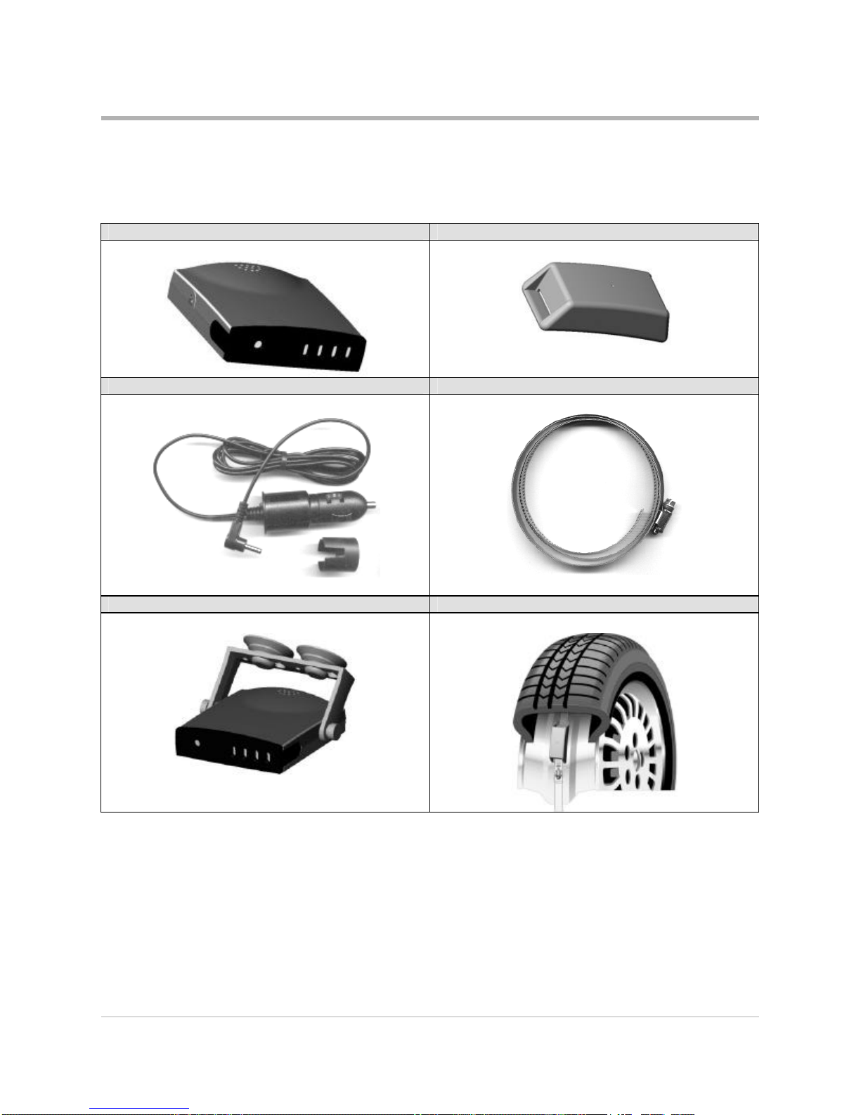
Component Images
Receiver Transmitter
Receiver cable and adaptor Strap for mounting transmitters
Receiver with mounting bracket and suction cups Transmitter mounted on wheel

SmarTire Systems Inc.
Tire Monitoring System Reference Manual
6/20/2000 Page 15 of 56
This manual is under review by SmarTire –DO NOT ISSUE
Pressure Alert Systems –2 and 4 wheels –Multi-fit Valve Mount Transmitters
Kit # 060.2004 (4 wheel) Product B
Kit # 060.2002 (2 wheel) Product I
Overview
These kits contain a base receiver, two or four valve mounted transmitters, installation hardware
and documentation for use on tires with a pressure up to 83 PSI (gauge).
The transmitters transmit pressure and temperature data when the vehicle attains a speed of 10
kph. Tire pressure and temperature are checked every six seconds and data is transmitted every 5
minutes.
The receiver annunciates a pressure loss incident at two severity levels. The initial warning
occurs when the pressure has dropped a set amount below the required pressure. A second
warning occurs when the pressure has dropped to a level considered critical to the support of the
vehicle. The affected tire is identified with a colour coded indicator on the receiver,
corresponding to the same colour code on the valve of the respective tire.
An optional serial port can send transmitter data to another customer device.
To install the system attach a transmitter to a suitable valve and mount in the valve hole. Plug the
receiver into the cigarette lighter plug with the supplied cable.
Note: Valves are not included with the kit.

SmarTire Systems Inc.
Tire Monitoring System Reference Manual
6/20/2000 Page 16 of 56
This manual is under review by SmarTire –DO NOT ISSUE
Bill of Materials
060.2004 Pressure Alert Systems –4 wheels –Multi-fit Valve Mount Transmitters
QTY PER
STOCK CODE Description
1 069.0001 INSTALLATION KIT
1 069.0002 POWER CABLE KIT
1 200.0059 RECEIVER -BASE-GENII
4 200.0065 TRANSMITTER-STRAP-GENII
1 276.0042 BOX -ELECTRONIC PARTS
1 276.0043 BAG TRANSMITTER SHIELD
1 700.0000 DOCUMENT KIT, GENII -BASIC
060.2004 Pressure Alert Systems –2 wheels –Multi-fit Valve Mount Transmitters
QTY PER
STOCK CODE Description
1 069.0001 INSTALLATION KIT
1 069.0002 POWER CABLE KIT
1 200.0059 RECEIVER -BASE-GENII
2 200.0065 TRANSMITTER-STRAP-GENII
1 276.0042 BOX -ELECTRONIC PARTS
1 276.0043 BAG TRANSMITTER SHIELD
1 700.0000 DOCUMENT KIT, GENII -BASIC

SmarTire Systems Inc.
Tire Monitoring System Reference Manual
6/20/2000 Page 17 of 56
This manual is under review by SmarTire –DO NOT ISSUE
Component Images
NOTE: Valve not included in kit
Receiver Transmitter
Receiver cable and adaptor Transmitter mounted with valve
Receiver with mounting bracket and suction cups Transmitter mounted on wheel

SmarTire Systems Inc.
Tire Monitoring System Reference Manual
6/20/2000 Page 18 of 56
This manual is under review by SmarTire –DO NOT ISSUE
Pressure Alert Full Function Display
Kit # 061.4000 LCD-I
Kit # 061.4001 LCD-R
Overview
The full function display is used with any existing system to extend the functionality of the basic
tire pressure monitoring system up to 20 tire positions. It provides a digital pressure and
temperature readout as well as diagnostic data such as transmitter battery life for each tire. The
user can also set his own pressure warning levels and adjust other parameters to suit a particular
tire.
Two models of the LCD exist, differing by their method of connecting to the base receiver. The
LCD-I clips onto the front of the receiver, while LCD-R is connected via a 6 ft. interconnecting
cable.
To install, remove the basic receiver bezel. Clip the LCD-I unit onto the front of the base
receiver (or connect the cable in the case of the LCD-R).

SmarTire Systems Inc.
Tire Monitoring System Reference Manual
6/20/2000 Page 19 of 56
This manual is under review by SmarTire –DO NOT ISSUE
Bill of Materials
061.4000 Pressure Alert Full Function Display –Type I
QTY PER
STOCK CODE Description
1
200.0060 LCD DISPLAY UNIT -TYPE I
1
276.0042 BOX -ELECTRONIC PARTS
1
700.0001 DOCUMENT KIT, GENII -LCD
061.4001 Pressure Alert Full Function Display –Type R
QTY PER
STOCK CODE Description
1
200.0060 LCD DISPLAY UNIT -TYPE I
260.0096 CABLE REMOTE LCD
1
276.0042 BOX -ELECTRONIC PARTS
1
700.0001 DOCUMENT KIT, GENII -LCD
Component Images
LCD-ILCD-R
LCD-I mounted with receiver LCD-R with cable to receiver

SmarTire Systems Inc.
Tire Monitoring System Reference Manual
6/20/2000 Page 20 of 56
This manual is under review by SmarTire –DO NOT ISSUE
Pressure Alert Flexible Power Adaptor
Kit # 061.3000
Overview
A flexible power adapter is plugged into the cigarette lighter socket and the receiver is mounted
on it so that it can be positioned by the driver for the best viewing position.
Bill of Materials
061.3000 Pressure Alert Flexible Power Adaptor
QTY PER
STOCK CODE Description
1
200.0066 POWER SHOE ASSY-GOOSENECK-GII
1
276.0042 BOX -ELECTRONIC PARTS
Component Image
Flexible Power Adaptor (Gooseneck) Mount
Receiver –LCD mounted on Power Adaptor Receiver -LCD-R mounted on Power Adaptor
Table of contents
Popular Measuring Instrument manuals by other brands

Pelstar
Pelstar Health o meter Professional ADULTHR User instructions

ScienTECH
ScienTECH 730 Installation, Operation and Care Manual

Deif
Deif MIB 8000 Designers handbook

Endress+Hauser
Endress+Hauser Proline Prowirl 73 technical information

Oakton
Oakton 35616-00 instruction manual

Shodex
Shodex KW400-4F Series Operation manual


PCB Piezotronics
PCB Piezotronics 3711E1125G Installation and operating manual

MARQUES
MARQUES BM 1000 user guide

Simpson
Simpson 260-8P instruction manual

Pfeiffer Vacuum
Pfeiffer Vacuum FullRange PBR 260 Short instructions

Buckleys
Buckleys 6004-0093 operating instructions

AFRISO
AFRISO DTA 20 E operating instructions