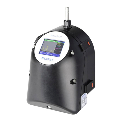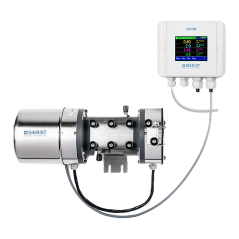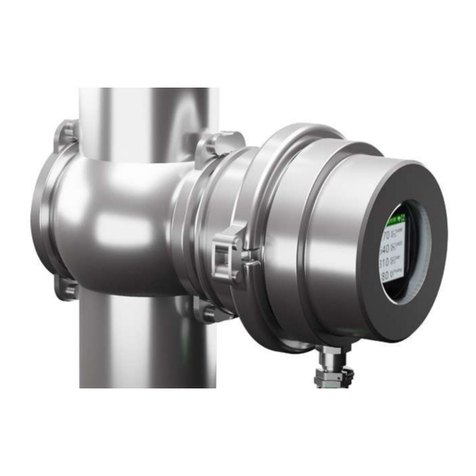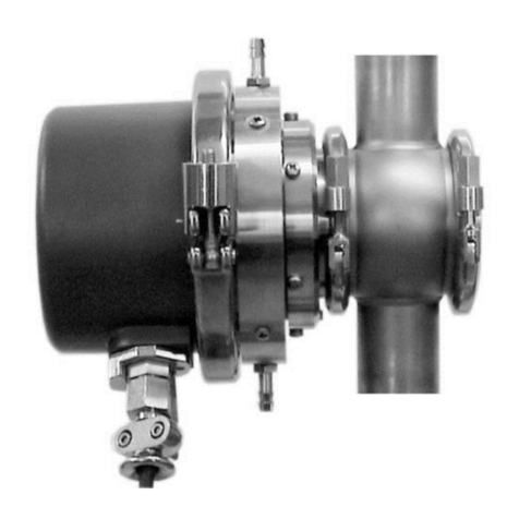
Instruction Manual AquaScat S Contents
4 13798E/3
5.3 Installation of the AquaScat S with SICON (M) ................................................39
5.3.1 Removing the cover from the SICON (M) ...................................................39
5.3.2 Overview of the opened SICON control unit ..............................................40
5.3.3 Installing the AquaScat S on the SICON (M)...............................................41
5.3.4 Installing the submerge version with special cable on the SICON ...............42
5.4 Connecting the field bus interfaces (optional) .................................................43
5.4.1 Overview of Modbus RTU and Profibus DP ................................................43
5.4.2 Connecting the Modbus RTU or Profibus DP..............................................44
5.4.3 Overview of Profinet IO .............................................................................44
5.4.4 Overview of HART .....................................................................................45
5.4.5 Connecting to HART..................................................................................45
5.5 Connecting the analog modules (optional) .....................................................46
5.5.1 Overview of 4-way current output .............................................................46
5.5.2 Connecting the 4-way current output .......................................................46
5.5.3 Overview of the 4-way current input .........................................................47
5.5.4 Connecting the 4-way current input..........................................................47
6Commissioning............................................................................................................48
6.1 Commissioning with Conn-R junction box and SICON-C.................................48
6.2 Commissioning with SICON (M)......................................................................49
6.3 Commissioning without SICON (M).................................................................50
7Operation ....................................................................................................................52
7.1 Operation basics .............................................................................................52
7.2 LED display in the Conn-R junction box...........................................................53
7.3 Control elements in measuring operation .......................................................54
7.4 Menu button ..................................................................................................54
7.5 Valu button ....................................................................................................54
7.6 Info button .....................................................................................................55
7.6.1 Page 1, Info button ...................................................................................55
7.6.2 Page 2, Info button ...................................................................................56
7.7 Diag button (with SICON (M) only) .................................................................57
7.8 Functions of the log screen (with SICON (M) only) ..........................................58
7.9 Displays in measuring operation......................................................................59
7.10 Lock / unlock the touch screen........................................................................60
7.11 Switching to service mode ..............................................................................61
7.12 Control components in service mode ..............................................................62
7.12.1 Input elements in service mode..................................................................62
7.12.2 Numerical entry .........................................................................................63
7.12.3 Single selection of functions ......................................................................64
7.12.4 Multiple selection of functions...................................................................64
8Settings .......................................................................................................................65
8.1 Setting the operating language.......................................................................65
8.2 Setting the current outputs.............................................................................66
8.3 Setting the limits.............................................................................................67
8.3.1 Upper and lower threshold value of a limit ................................................68
8.3.2 Reading if limit exceeded or undershot ......................................................68
8.4 Setting the outputs .........................................................................................69
8.5 Setting the Profibus DP parameters.................................................................70
8.6 Setting the Profinet IO parameters ..................................................................71
8.7 Setting the Modbus RTU parameters ..............................................................72
8.8 Setting the date and time ...............................................................................73
8.9 Setting or changing the access code ...............................................................74
8.10 Backup configured data..................................................................................75
9Servicing......................................................................................................................76


