SAFETY INFORMATION
B001457
SAFETY INFORMATION
WARNING
•No smoking! No open fire or heat sources!
•The product was developed, manufactured,
and inspected according to the asic safety
requirements of EC Guidelines and state-of-
the-art technology.
•The instrument is designed for use in grounded
vehicles and machines as well as in pleasure
oats, including non-classified commercial
shipping.
•Use our product only as intended. Use of the
product for reasons other than its intended use
may lead to personal injury, property damage
or environmental damage. Before installation,
check the vehicle documentation for vehicle
type and any possi le special features!
•Use the assem ly plan to learn the location of
the fuel/hydraulic/compressed air and
electrical lines!
•Note possi le modifications to the vehicle,
which must e considered during installation!
•To prevent personal injury, property damage or
environmental damage, asic knowledge of
motor vehicle/ship uilding electronics and
mechanics is required.
•Make sure that the engine cannot start
unintentionally during installation!
•Modifications or manipulations to veratron
products can affect safety. Consequently, you
may not modify or manipulate the product!
•When removing/installing seats, covers, etc.,
ensure that lines are not damaged and plug-in
connections are not loosened!
•Note all data from other installed instruments
with volatile electronic memories.
SAFETY DURING INSTALLATION
•During installation, ensure that the product’s
components do not affect or limit vehicle
functions. Avoid damaging these components!
•Only install undamaged parts in a vehicle!
•During installation, ensure that the product
does not impair the field of vision and that it
cannot impact the driver’s or passenger’s head!
•A specialized technician should install the
product. If you install the product yourself,
wear appropriate work clothing. Do not wear
loose clothing, as it may get caught in moving
parts. Protect long hair with a hair net.
•When working on the on- oard electronics, do
not wear metallic or conductive jewelry such as
necklaces, racelets, rings, etc.
•If work on a running engine is required, exercise
extreme caution. Wear only appropriate work
clothing as you are at risk of personal injury,
resulting from eing crushed or urned.
•Before eginning, disconnect the negative
terminal on the attery, otherwise you risk a
short circuit. If the vehicle is supplied y
auxiliary atteries, you must also disconnect
the negative terminals on these atteries!
Short circuits can cause fires, attery
explosions and damages to other electronic
systems. Please note that when you disconnect
the attery, all volatile electronic memories
lose their input values and must e
reprogrammed.
•If working on gasoline oat motors, let the
motor compartment fan run efore eginning
work.
•Pay attention to how lines and ca le harnesses
are laid so that you do not drill or saw through
them!
•Do not install the product in the mechanical
and electrical air ag area!
•Do not drill holes or ports in load- earing or
sta ilizing stays or tie ars!
•When working underneath the vehicle, secure
it according to the specifications from the
vehicle manufacturer.
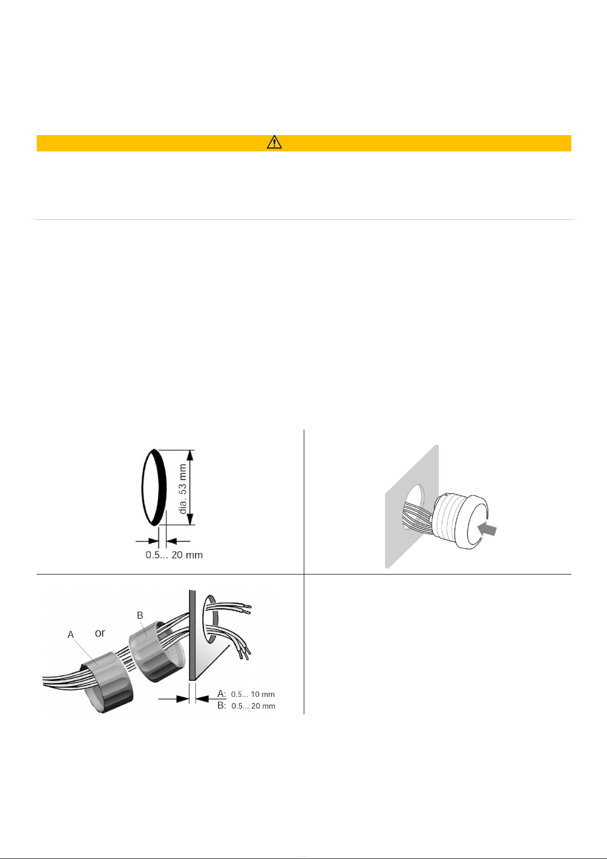
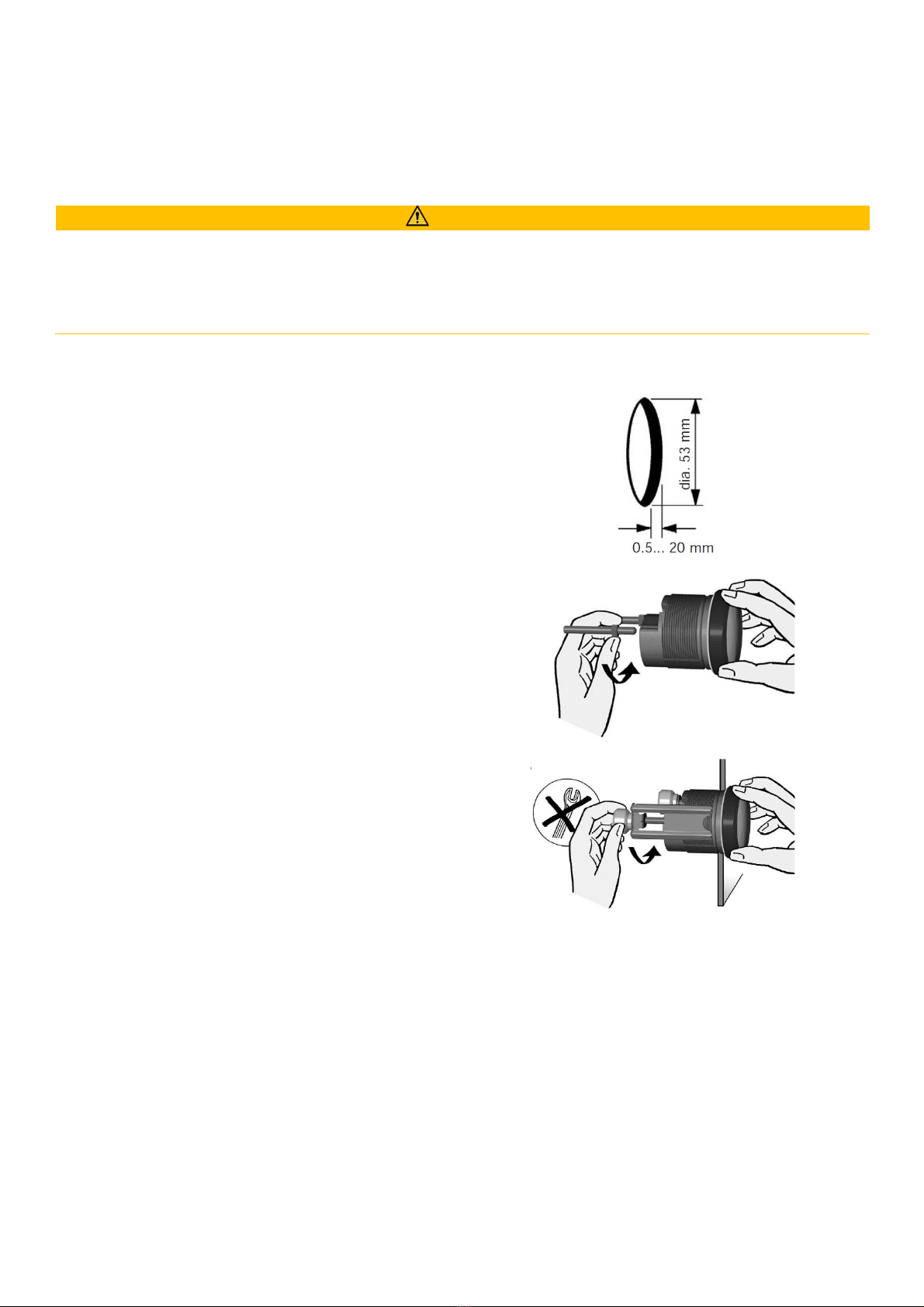
•Note the necessary clearance ehind the drill
hole or port at the installation location.
Required mounting depth: 65 mm.
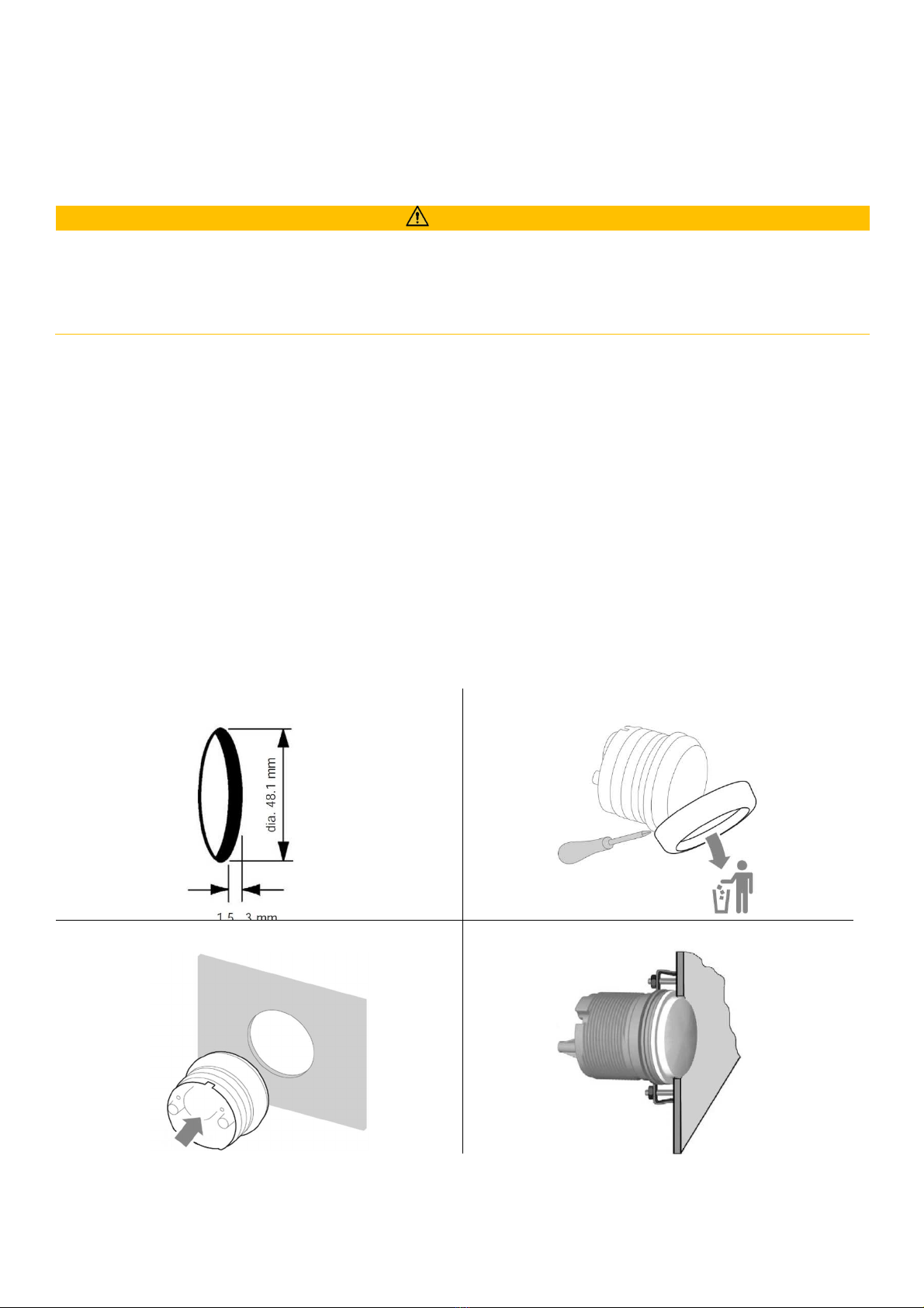
•Drill small ports; enlarge and complete them, if
necessary, using taper milling tools, sa er saws,