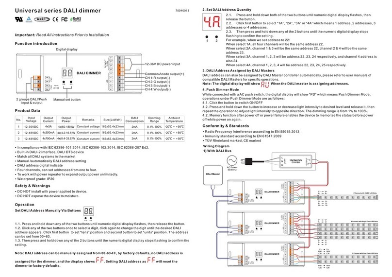
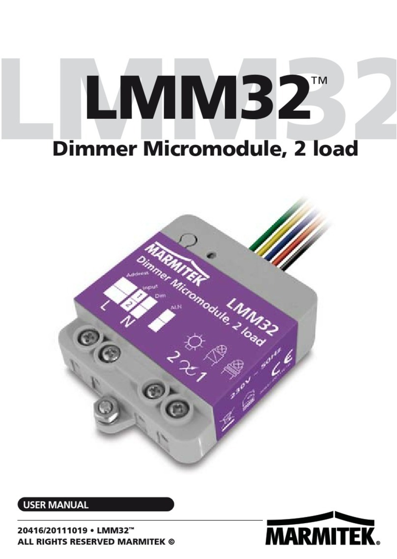
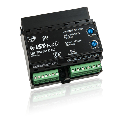
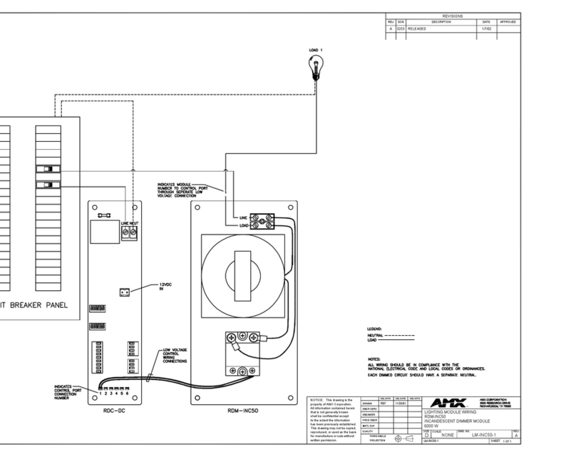
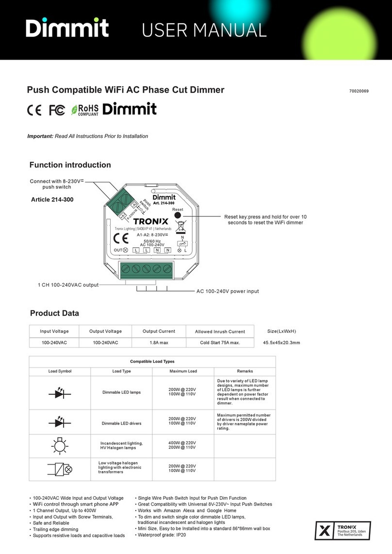
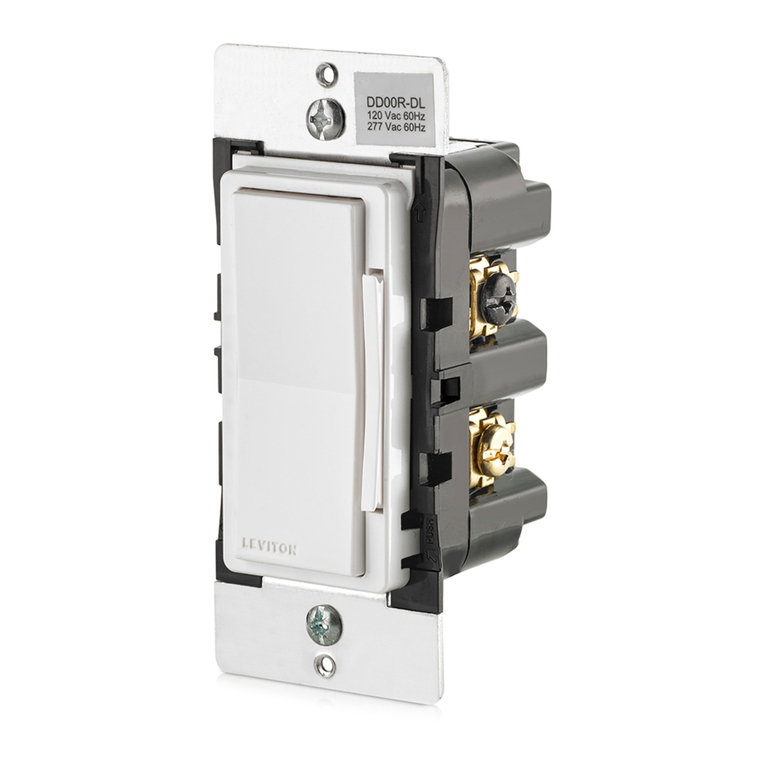
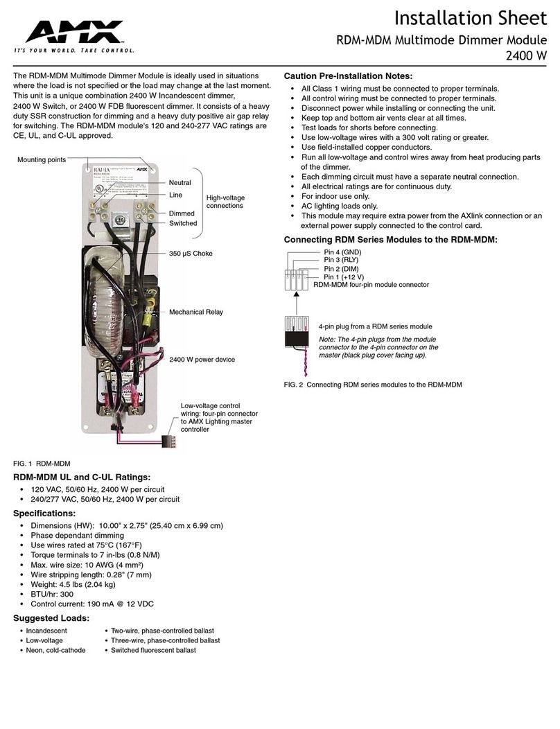
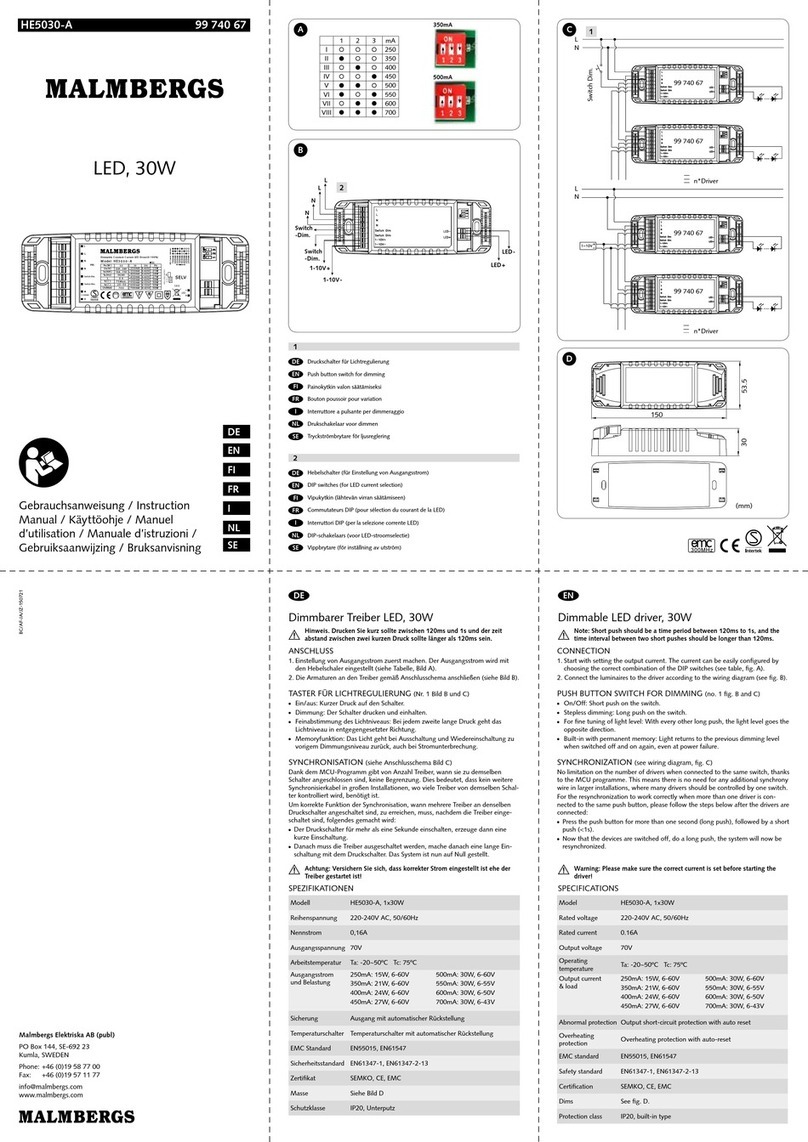
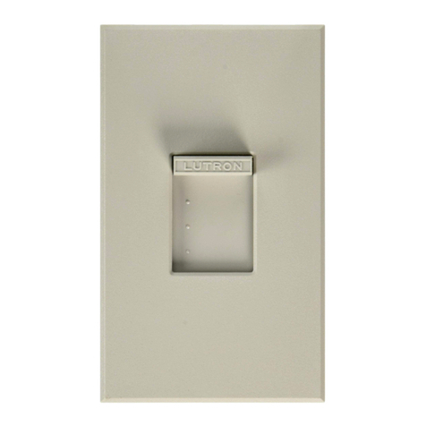
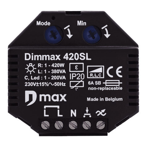
SmartLinc SwitchLinc Lite User manual

SSwwiittcchhLLiinnccLLiittee
Remote Control Dimmer Switch
OOwwnneerr’’ssMMaannuuaall
For Models #2384W/I
(and Slave Remote Dimmer Model #1135W/I)
LIMITED WARRANTY
Copyright 1999 SmartLinc
17201 Daimler Street
Irvine, CA92614
(main) 949.221.0480
(fax) 949.221.0488
www.smartlinc.com
email: [email protected]
10/99

CONGRATULATIONS!
You’ve just purchased the highest quality powerline-controllable wall switch available. SwitchLinc Lite
gives you remote control of lighting and inductive loads, and can be controlled locally at the switch or
remotely from a powerline transmitter.
SwitchLinc Lite is easily installed and programmed. It installs (connects to home wiring) just like a
regular light switch. This makes it ideal for retrofits and easy for new homes, with no special training
required to install it.
KEYFEATURES
• Wires in just like a standard wall switch*
• Very easy to program
• High quality mechanicals with years of field testing
• True rocker action (top = on/bright, bottom = off/dim)
• LED “Bar” shows brightness of circuit
• Status LED shows powerline activity and is a “nightlight”
• Set Button facilitates programming
* Requires a neutral connection
SWITCHLINC LITE MODELS
Model # 2384W/I - 600 Watt Master (White or Ivory)
Model # 1135W/I - “Slave” Switch for 3-Way, 4-Way, & Up (White or Ivory)
(Note: 1135 does not have LED brightness bar.)
OPERATIONS
Input at Switch Output at Bulb
Tap top of rocker (when light is off) Light ramps up to preset ON-level
Tap top of rocker (when light is on) Light ramps up to full brightness
Double-tap top of rocker Light ramps fast to full brightness
Press & hold top of rocker Light brightens until rocker is released
Tap bottom of rocker Light ramps down to OFF
Double-tap bottom of rocker Light ramps fast to OFF
Press & hold bottom of rocker Light dims until rocker is released
LED Operation
Status LED/Nightlight Blinks when valid X-10 signals are received
Brightness LED “Bar” (8 LEDs) Illuminated LED represents current brightness
setting (Top = Brightest; Bottom = Dimmest)
2
Brightness LED Bar
Status LED/Nightlight
Set Button
CAUTION!!
Read and understand these instructions before installing.This device is intended for instal-
lation in accordance with the National Electrical Code and local regulations. To reduce the
risk of overheating and possible damage to other equipment, do not install a SwitchLinc to
control a receptacle or fluorescent lighting fixture. For indoor use only. Connect only cop-
per or copper-clad wire to this device. Before installing control, disconnect power at circuit
breaker or remove fuse to avoid shock or damage to the control. It is recommended that a
qualified electrician perform this installation. Retain these instructions for future reference.
7
SPECIFICATIONS
• Load types: permanently installed incandescent and general inductive loads
• Single pole or multi-location (with Slave Dimmers)
• Operation: Dimming Triac
• Maximum load: 600 watts / 600 VA
• Input power: 125 VAC, 5 amps, 60 Hz
• Connections (16 AWG): Black (to line)
Red (to load)
White (to neutral, required)
Yellow (to optional “multi-way” circuit slaves (1135))
• Addresses: 1 PLC (X-10) Base (Primary) Address of 256 possible
• On-Level: 1 of 31 possible (3.2%-100%) or resume dim
• Ramp Rate: 0.125 seconds to 9 seconds
• Maximum number of SwitchLincs per multiple-gang box: 4
• Maximum number of SwitchLincs per circuit: 10 (with more than 6, a PLC amplified
coupler-repeater is highly recommended)
• Minimum load: 40W
• Operating temperature range: -40 oF to 104oF
• Minimum PLC transmit level: 2V
• Minimum PLC receive level: 10mV
• Maximum PLC signal rejection: 200mV
• Mounts in single or multiple-ganged J-box
(Note:When 2 units are ganged together, use no more than a 500 watt load on each unit;
when 3 or more units are ganged together, use no more than a 400 watt load on each unit.
To avoid downgrading load control, use a larger box than needed to create space between
the switches.)
• Nightlight indicator: Green LED
• Brightness indicator: 8 Green LEDs
• Dimensions - 4” x 1 11/16” x 1 7/8”
• Weight - 4 oz.
• Programming can be disabled (locked out)
• Switch can be physically disabled (and a hard “reboot” achieved) by a
firm OFF press
• U.L. Listed for use in the U.S. and Canada
WARNING!!
Dimming an inductive load (such as a ceiling fan) below the minimum voltage set by the
manufacturer of the load device could cause damage to the load device from overheating.
If the manufacturer of the load device does not recommend dimming, DO NOT use Switch-
Linc Lite with that device. USER ASSUMES ALLRISKS ASSOCIATED WITH DIM-
MINGAN INDUCTIVE LOAD.

PREPARATION
Before installing SwitchLinc Lite, please familiarize yourself with the following and take the necessary
precautions listed here:
•Be sure that power to the load being controlled has been disconnected by removing the fuse or
turning the circuit breaker off. Installing SwitchLinc Lite with the power on may expose you to
dangerous voltages and may damage the product.
•Refer to the SwitchLinc Wiring Diagrams below to determine the wire colors of the connections
to SwitchLinc Lite. Note: All SwitchLinc Lites require a neutral connection.
•Wiring for 3-way, 4-way, & up switch circuits follow conventional (standard, non-remote) wiring
practice (plus the requirement for a neutral). Wiring “slave” switches requires the Line (Black)
wire be accessible and be on the same 110Vleg of the house wiring. The Grey wire on the
“slave” switch is to be connected to NEUTRALONLY. If neutral is not available, cap the Grey
wire (which simply causes the LEDnot to function).
•SwitchLinc Lite may feel warm during operation. The amount of heat generated is within U.L.
approved limits and poses no hazards. To minimize heat build-up, ensure that the area surround-
ing the rear of the SwitchLinc Lite has adequate ventilation (i.e., clear away excess insulation).
•Installation should be performed only by a qualified electrician, or by a homeowner who is
familiar and comfortable with electrical circuitry.
•Follow all routine safety precautions.
INSTALLATION
1. Remove the power from the existing switch/device.
2. Remove the faceplate from the existing switch/device.
3. Unscrew and pull the device out of the wallbox.
4. Disconnect the wires from the device.
5. Using a wire tester or voltmeter, identify and mark "Hot", “Neutral”, “Ground”, and “Traveler” (if
applicable) wires that were connected to the device.
6. Before making any connections to SwitchLinc Lite, FIRMLYPRESS SWITCHLINC LITE’S
ROCKER BOTTOM UNTILYOU HEAR ACLICK. A“System Off” sticker will be exposed on
the top of the rocker.
7. Orient SwitchLinc Lite so the LED is at the top, and make connections according to the “Switch-
Linc Wiring Diagram” below. Wire “slave” switches according to the “SwitchLinc Multi-Way
Wiring Diagram” on page 4.
3
SETTING GLOBAL(HOUSE-WIDE) OPTIONS
Disable Program
(Prevents accidental programming of SwitchLinc settings for all SwitchLincs in the home)
Transmit the following PLC sequence: M16, O16, P16, N16, P16
(Re-)Enable Program (default)
Transmit the following PLC sequence: N16, M16, O16, P16, P16
POWER RESTORE
SwitchLinc Lite will return the lighting circuit being controlled to its last brightness level when
power is restored after a power outage.
6
Main Panel
120VAC
Line
Neutral
Red
Ground
Load
SwitchLinc 2-Way
(Model 1181 or 1182)
Neutral
SwitchLinc Wiring Diagram
White
Light
Fixture
(s)
Yellow
Black
cap this lead
SwitchLinc Lite
(Model 2384)
Problem Possible Cause Solution
TROUBLESHOOTING & TECHNICALSUPPORT
Light comes ON too Ramp rate may be set Increase ramp rate if desired
slowly or goes OFF too slow
too slowly when
SwitchLinc is
tapped (manually)
SwitchLinc will not SwitchLinc may be in Re-enable Program mode, or perform
take programming Program Disable mode a Factory Reset to reset SwitchLinc
of ramp rate, etc. to factory defaults
SwitchLinc is locked Surge in power line Reset SwitchLinc by pressing bottom of
up or working rocker until it clicks into System
only intermittently Off mode, then release
LED is not visible Circuit breaker is offTurn circuit breaker on or connect fuse
and/or SwitchLInc
is not controlling SwitchLinc is in the Snap top of SwitchLinc into operating
the light System Off position mode
Insufficient load Increase load to meet minimum load
requirements
Incomplete (open) wire Check wallbox wires to ensure all
connection in wallbox connections are tight and no bare
wire is exposed
Incomplete (open) wire Check fixture to ensure all connections
connection at fixture are tight and no bare wire is exposed

8. After all connections have been made, ensure that all wire connectors are firmly attached and that
there is no exposed copper.
9. Gently place the wires and switch into the wallbox (with LED at top of device) and screw into
place.
10. Before installing the faceplate, restore power to the circuit, and firmly press SwitchLinc Lite’s
rocker top until the switch snaps out of “System Off” position.
11. After testing SwitchLinc Lite for proper operation (as described on page 2), install the faceplate.
PROGRAMMING
Setting the Primary Address
Each SwitchLinc Lite requires a primary X-10 address to operate (ships with “A1” from the factory; up
to 256 addresses can be programmed with Housecodes A-Pand Unit Codes 1-16).
Please note that the following Housecode and Unit Code combinations should not be
assigned as primary addresses orscene addresses, because they are reserved forprogram-
ming: M16, N16, O16, and P16
1. Using the tip of a very small screwdriver, press and hold the small Set Button in the middle of
the righthand side of SwitchLinc Lite (see diagram on page 2) for approximately 5 seconds, until
the brightness LED flashes (and the light goes to 100% brightness). When you release the Set
Button, the nightlight LED will flash.
2. Within 30 seconds, transmit the desired primary address (housecode and unit code) from any
transmitter (e.g., TouchLinc). The light will blink and the nightlight LED will stop flashing.
Setting the Ramp Rate (Optional)
The “Ramp Rate” is the rate at which SwitchLinc Lite brings the brightness of the light up or down
when the switch is turned on locally or receives a powerline carrier (X-10) ON-command to its primary
address. The Ramp Rate is adjustable. The factory default is about 3 seconds. If you wish to change
the ramp rate, follow the instructions below.
4
Main Panel
120VAC
Line
Neutral
Red
Ground
Load
SwitchLinc 2-Way
(Model 1181 or 1182)
Neutral
SwitchLinc Multi-Way Wiring Diagram
Black Black
Grey WhiteGrey
Light
Fixture
(s)
YellowYellow
Black
GroundGround
Optional Slave Switches
(Model 1135)
Note: When installing multiple SwitchLincs in a J-box, or many on the same circuit breaker, please see
specifications at the end of this manual for limitations and recommendations.
SwitchLinc Lite
(Model 2384)
5
1. Press and hold the rocker to adjust the Brightness LED level to correspond to the the desired
ramp rate (brighter = faster) according to the following table.
2. Tap the Set Button TWICE. The light will blink.
Setting the ON-Level (Optional)
The ON-Level is the default brightness level to which SwitchLinc Lite will adjust the light when the
switch is turned on locally or receives a powerline carrier (X-10) ON-command to its primary address.
The factory default is 100%. You can set the ON-Level to a fixed brightness level or to resume its
previous brightness level.
Setting a fixed brightness level:
1. Adjust the brightness of the light to the desired level by pressing and holding SwitchLinc’s
rocker.
2. Tap the Set Button ONCE. The light will blink.
Setting resume dim:
1. Turn the light off.
2. Tap the Set Button ONCE.
FACTORYRESET (TO DEFAULT SETTINGS)
1. Firmly press the bottom of the SwitchLinc Lite rocker until you hear a loud click. A“System
Off” sticker will be exposed on the top of the rocker.This completely removes the power from
the lighting circuit being controlled by the SwitchLinc Lite.
2. Press and hold the Set Button.
3. While continuing to hold the Set Button, press the top of the SwitchLinc rocker (as if to turn the
switch on).
4. Release the Set Button.
5. WAIT approximately 25 seconds until the Nightlight LED illuminates before using the switch
(SwitchLinc is rewriting all options to be as they were when they shipped from the factory).
Brightness LED Level Ramp Rate in Seconds
80.1
70.2
60.3
50.5
42.0
34.5
26.5
18.5
NO LED 9.0

PREPARATION
Before installing SwitchLinc Lite, please familiarize yourself with the following and take the necessary
precautions listed here:
•Be sure that power to the load being controlled has been disconnected by removing the fuse or
turning the circuit breaker off. Installing SwitchLinc Lite with the power on may expose you to
dangerous voltages and may damage the product.
•Refer to the SwitchLinc Wiring Diagrams below to determine the wire colors of the connections
to SwitchLinc Lite. Note: All SwitchLinc Lites require a neutral connection.
•Wiring for 3-way, 4-way, & up switch circuits follow conventional (standard, non-remote) wiring
practice (plus the requirement for a neutral). Wiring “slave” switches requires the Line (Black)
wire be accessible and be on the same 110Vleg of the house wiring. The Grey wire on the
“slave” switch is to be connected to NEUTRALONLY. If neutral is not available, cap the Grey
wire (which simply causes the LEDnot to function).
•SwitchLinc Lite may feel warm during operation. The amount of heat generated is within U.L.
approved limits and poses no hazards. To minimize heat build-up, ensure that the area surround-
ing the rear of the SwitchLinc Lite has adequate ventilation (i.e., clear away excess insulation).
•Installation should be performed only by a qualified electrician, or by a homeowner who is
familiar and comfortable with electrical circuitry.
•Follow all routine safety precautions.
INSTALLATION
1. Remove the power from the existing switch/device.
2. Remove the faceplate from the existing switch/device.
3. Unscrew and pull the device out of the wallbox.
4. Disconnect the wires from the device.
5. Using a wire tester or voltmeter, identify and mark "Hot", “Neutral”, “Ground”, and “Traveler” (if
applicable) wires that were connected to the device.
6. Before making any connections to SwitchLinc Lite, FIRMLYPRESS SWITCHLINC LITE’S
ROCKER BOTTOM UNTILYOU HEAR ACLICK. A“System Off” sticker will be exposed on
the top of the rocker.
7. Orient SwitchLinc Lite so the LED is at the top, and make connections according to the “Switch-
Linc Wiring Diagram” below. Wire “slave” switches according to the “SwitchLinc Multi-Way
Wiring Diagram” on page 4.
3
SETTING GLOBAL(HOUSE-WIDE) OPTIONS
Disable Program
(Prevents accidental programming of SwitchLinc settings for all SwitchLincs in the home)
Transmit the following PLC sequence: M16, O16, P16, N16, P16
(Re-)Enable Program (default)
Transmit the following PLC sequence: N16, M16, O16, P16, P16
POWER RESTORE
SwitchLinc Lite will return the lighting circuit being controlled to its last brightness level when
power is restored after a power outage.
6
Main Panel
120VAC
Line
Neutral
Red
Ground
Load
SwitchLinc 2-Way
(Model 1181 or 1182)
Neutral
SwitchLinc Wiring Diagram
White
Light
Fixture
(s)
Yellow
Black
cap this lead
SwitchLinc Lite
(Model 2384)
Problem Possible Cause Solution
TROUBLESHOOTING & TECHNICALSUPPORT
Light comes ON too Ramp rate may be set Increase ramp rate if desired
slowly or goes OFF too slow
too slowly when
SwitchLinc is
tapped (manually)
SwitchLinc will not SwitchLinc may be in Re-enable Program mode, or perform
take programming Program Disable mode a Factory Reset to reset SwitchLinc
of ramp rate, etc. to factory defaults
SwitchLinc is locked Surge in power line Reset SwitchLinc by pressing bottom of
up or working rocker until it clicks into System
only intermittently Off mode, then release
LED is not visible Circuit breaker is offTurn circuit breaker on or connect fuse
and/or SwitchLInc
is not controlling SwitchLinc is in the Snap top of SwitchLinc into operating
the light System Off position mode
Insufficient load Increase load to meet minimum load
requirements
Incomplete (open) wire Check wallbox wires to ensure all
connection in wallbox connections are tight and no bare
wire is exposed
Incomplete (open) wire Check fixture to ensure all connections
connection at fixture are tight and no bare wire is exposed

CONGRATULATIONS!
You’ve just purchased the highest quality powerline-controllable wall switch available. SwitchLinc Lite
gives you remote control of lighting and inductive loads, and can be controlled locally at the switch or
remotely from a powerline transmitter.
SwitchLinc Lite is easily installed and programmed. It installs (connects to home wiring) just like a
regular light switch. This makes it ideal for retrofits and easy for new homes, with no special training
required to install it.
KEYFEATURES
• Wires in just like a standard wall switch*
• Very easy to program
• High quality mechanicals with years of field testing
• True rocker action (top = on/bright, bottom = off/dim)
• LED “Bar” shows brightness of circuit
• Status LED shows powerline activity and is a “nightlight”
• Set Button facilitates programming
* Requires a neutral connection
SWITCHLINC LITE MODELS
Model # 2384W/I - 600 Watt Master (White or Ivory)
Model # 1135W/I - “Slave” Switch for 3-Way, 4-Way, & Up (White or Ivory)
(Note: 1135 does not have LED brightness bar.)
OPERATIONS
Input at Switch Output at Bulb
Tap top of rocker (when light is off) Light ramps up to preset ON-level
Tap top of rocker (when light is on) Light ramps up to full brightness
Double-tap top of rocker Light ramps fast to full brightness
Press & hold top of rocker Light brightens until rocker is released
Tap bottom of rocker Light ramps down to OFF
Double-tap bottom of rocker Light ramps fast to OFF
Press & hold bottom of rocker Light dims until rocker is released
LED Operation
Status LED/Nightlight Blinks when valid X-10 signals are received
Brightness LED “Bar” (8 LEDs) Illuminated LED represents current brightness
setting (Top = Brightest; Bottom = Dimmest)
2
Brightness LED Bar
Status LED/Nightlight
Set Button
CAUTION!!
Read and understand these instructions before installing.This device is intended for instal-
lation in accordance with the National Electrical Code and local regulations. To reduce the
risk of overheating and possible damage to other equipment, do not install a SwitchLinc to
control a receptacle or fluorescent lighting fixture. For indoor use only. Connect only cop-
per or copper-clad wire to this device. Before installing control, disconnect power at circuit
breaker or remove fuse to avoid shock or damage to the control. It is recommended that a
qualified electrician perform this installation. Retain these instructions for future reference.
7
SPECIFICATIONS
• Load types: permanently installed incandescent and general inductive loads
• Single pole or multi-location (with Slave Dimmers)
• Operation: Dimming Triac
• Maximum load: 600 watts / 600 VA
• Input power: 125 VAC, 5 amps, 60 Hz
• Connections (16 AWG): Black (to line)
Red (to load)
White (to neutral, required)
Yellow (to optional “multi-way” circuit slaves (1135))
• Addresses: 1 PLC (X-10) Base (Primary) Address of 256 possible
• On-Level: 1 of 31 possible (3.2%-100%) or resume dim
• Ramp Rate: 0.125 seconds to 9 seconds
• Maximum number of SwitchLincs per multiple-gang box: 4
• Maximum number of SwitchLincs per circuit: 10 (with more than 6, a PLC amplified
coupler-repeater is highly recommended)
• Minimum load: 40W
• Operating temperature range: -40 oF to 104oF
• Minimum PLC transmit level: 2V
• Minimum PLC receive level: 10mV
• Maximum PLC signal rejection: 200mV
• Mounts in single or multiple-ganged J-box
(Note:When 2 units are ganged together, use no more than a 500 watt load on each unit;
when 3 or more units are ganged together, use no more than a 400 watt load on each unit.
To avoid downgrading load control, use a larger box than needed to create space between
the switches.)
• Nightlight indicator: Green LED
• Brightness indicator: 8 Green LEDs
• Dimensions - 4” x 1 11/16” x 1 7/8”
• Weight - 4 oz.
• Programming can be disabled (locked out)
• Switch can be physically disabled (and a hard “reboot” achieved) by a
firm OFF press
• U.L. Listed for use in the U.S. and Canada
WARNING!!
Dimming an inductive load (such as a ceiling fan) below the minimum voltage set by the
manufacturer of the load device could cause damage to the load device from overheating.
If the manufacturer of the load device does not recommend dimming, DO NOT use Switch-
Linc Lite with that device. USER ASSUMES ALLRISKS ASSOCIATED WITH DIM-
MINGAN INDUCTIVE LOAD.
This manual suits for next models
4
