Seebacher ISYGLT UD-700-X2-DALI User manual
Seebacher GmbH www.seebacher.de Phone: +49 (0) 80 41 / 77 77 6
Marktstrasse 57, 83646 Bad Tölz info@seebacher.de Fax: +49 (0) 80 41 / 77 77 2
1
Technical Data / Instruction Manual
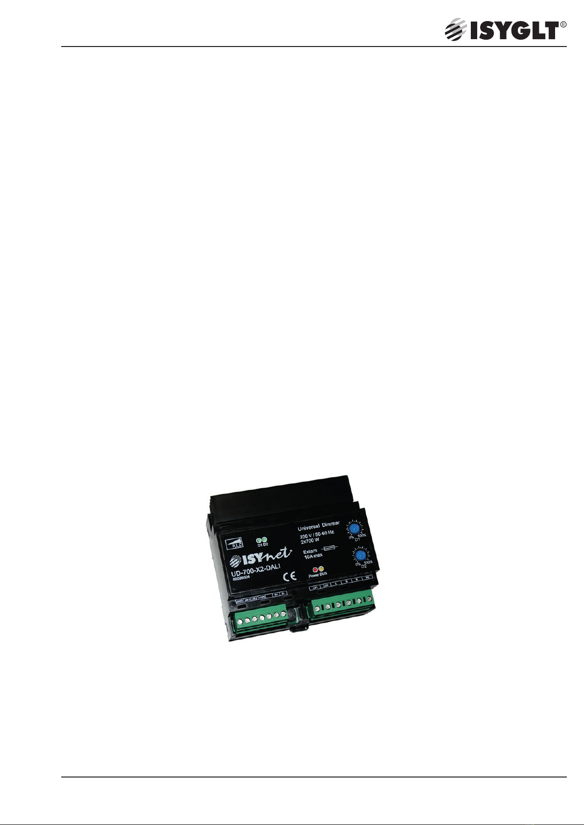
UD-700-X2-DALI
Article no. 80026504
DALI Universal Dimmer

Seebacher GmbH www.seebacher.de Phone: +49 (0) 80 41 / 77 77 6
Marktstrasse 57, 83646 Bad Tölz info@seebacher.de Fax: +49 (0) 80 41 / 77 77 2
2
1. Notes on documentation
These instructions are intended for qualified personnel who are
familiar with the assembly, installation and operation of the ISYGLT
system. It is essential that you read these operating instructions
through before commissioning and keep them accessible for further
use.
SEEBACHER cannot accept any liability for damage or malfunctions
resulting from failure to observe these instructions.
1.1. Retention of documents
These instructions and all other applicable documents are part
of the product. They must be handed over to the device operator.
The operator will store the documents so that they can be made
available if necessary.
1.2. Symbols used
Observe the following safety and other instructions in the manual:
Handling instruction
The hand indicates that you should carry out an act.
Danger!
Immediate danger to life!
Attention!
General notes, useful information and special features
Directory of Content
1. Notes on documentation
1.1. Retention of documents
1.2. Symbols used
2. Safety instructions
2.1. Intended usage
2.2. Predictable mishandling
2.3. Safe handling
2.4. Qualification of staff
2.5. Changes to the product
2.6. Use of spare parts and additional equipment
2.7. Liability notes
3. Warranty
4. Declaration of Conformity
5. Service address
6. Maintenance / Care / Disposal
7. Storage
8. Assembly
9. Product description
10. Technical Data
10.1. Pin assignment
11. Wiring diagram

Seebacher GmbH www.seebacher.de Phone: +49 (0) 80 41 / 77 77 6
Marktstrasse 57, 83646 Bad Tölz info@seebacher.de Fax: +49 (0) 80 41 / 77 77 2
3
The module is designed for cabinet installation on a 35mm DIN
rail according to EN 60715 in corresponding standard housings.
Extreme environmental conditions impair the function of the pro-
duct.
• Protect module from shocks
• Use module indoors only
• Protect module from humidity
In addition to these safety instructions, you must also observe
the special safety instructions listed in the individual chapters for
the individual acts.
2.4. Qualification of staff
Assembly, commissioning, operation, maintenance, decommis-
sioning and disposal may only be carried out by qualified staff.
Work on electrical parts may only be carried out by a trained
electrician in accordance with the applicable regulations and
directives. Other activities in connection with the ISYGLT module,
such as assembly and installation of system components with
tested standard plug connections, as well as operation and con-
figuration of the ISYGLT module may only be carried out by trai-
ned staff.
2.5. Changes to the product
Unauthorized modifications to the ISYGLT module which are not
described in this or the other applicable instructions can lead to
malfunctions and are prohibited for safety reasons.
2.6. Use of spare parts and additional equipment
The module may be damaged if unsuitable spare parts and addi-
tional equipment are used. Only use original spare parts and
additional equipment from the manufacturer.
2.7. Liability notes
SEEBACHER accepts no liability or warranty whatsoever for
damage and consequential damage caused by non-compliance
with the technical regulations, instructions and recommendati-
ons. SEEBACHER shall not be liable for any costs or damage
incurred by the user or third parties as a result of the use of this
equipment, in particular improper use of the equipment, misuse
or malfunction of the connection, malfunction of the equipment
or connected devices.
SEEBACHER accepts no liability for printing errors.
2. Safety instructions
Observe the following general safety instructions when installing
and commissioning the device:
Assembly and installation of the ISYGLT module may only be carried
out by a qualified electrician. Other activities in connection with the
ISYGLT module, such as assembly and installation of system com-
ponents with tested standard plug connections, as well as operation
and configuration of the ISYGLT module may only be carried out by
trained staff.
Observe the electrical installation regulations of the country in which
the device is installed and operated as well as its national accident
prevention regulations. In addition, observe internal company regu-
lations (work, operating and safety regulations).
Before working on the ISYGLT module system, it must be
disconnected from the power supply and secured against
being switched on again. After completion of the assembly,
installation and maintenance work, an electrical check must
be carried out! Check all protective conductor connections
and the voltages at all connection plugs as well as at each
individual module slot.
2.1. Intended usage
The module is exclusively suitable for regulation (control) in con-
nection with ISYGLT system components. Any other use is not
intended. The limit values stated in the technical data must not be
exceeded under any circumstances. This applies in particular to
the permissible ambient temperature range and the permissible
IP protection type. For applications with a higher required IP pro-
tection type, the ISYGLT module must be installed in a housing
or a cabinet with a higher IP protection type.
2.2. Predictable mishandling
The module must not be used in the following cases in particular:
•explosive area
When operating in explosive areas, sparking can lead to defla-
gration, fire or explosions.
2.3. Safe handling
This module corresponds to the state of the art and the recog-
nised safety regulations. Each device is tested for function and
safety before delivery.
Only operate this module in perfect condition in accordance with
the operating instructions, the applicable regulations and directi-
ves of the country in which the device is installed and operated,
and the applicable safety and accident prevention regulations.
Seebacher GmbH www.seebacher.de Phone: +49 (0) 80 41 / 77 77 6
Marktstrasse 57, 83646 Bad Tölz info@seebacher.de Fax: +49 (0) 80 41 / 77 77 2
4
6. Maintenance / Care / Disposal
The product is maintenance-free. It is sufficient from time to time to
remove any dust deposits. This may only be done in a power-free
state.
Disposal (European Union)
Do not dispose of product in household waste! Products with this
symbol
7. Storage
The product must be stored in a dry place, protected from dirt and
mechanical stress. After damp or dirty storage, the product may only
be operated after a condition check by an authorised electrician.
8. Assembly
(Only by certified electrician!)
Mount the product only when it is in a power-free state!
Switch off the power supply, check that there is no voltage, secure
against being switched on again!
The device may only be operated at voltages according to the tech-
nical data and loaded with the currents defined therein. Only use
suitable equipment (system modules).
Check that there are no loose parts in the product. If this is the case
and the presence of such parts is not explicitly described, do not
install or commission the product.
Only use suitable cables and fixing screws.
Assembly site
• The product can be installed in any position in a casing to be deter-
mined by the electrician (distribution box, switch cabinet). Observe
maximum ambient temperature!
Assembly steps
(Read completely before assembly!)
• Mount the device in a suitable casing.
• Make the electrical connections according to the wiring diagram.
• Configure the DIP switches according to your requirements.
• Only after a complete connection and a visual test by a qualified
electrician, the system may be put under voltage.
Seebacher GmbH
Marktstrasse 57
83646 Bad Tölz
GERMANY
Phone: +49 (0) 80 41 / 77 77 6
Fax: +49 (0) 80 41 / 77 77 2
www.seebacher.de
info@seebacher.de
5. Service address
4. Declaration of Conformity
The valid declaration of conformity for the module can be requested
from us free of charge by stating type and article no. as follows:
By phone: +49(0)8041/77776
By fax: +49(0)8041/77772
By mail: info@seebacher.de
3. Warranty
We provide warranty within the framework of the statutory provisi-
ons. These are limited to the intended use of the module and refer
to the repair or replacement of the ISYGLT module. Please send the
device with an attached error description to our company address
given below.
must be disposed of according to the EU directive WEEE 2012/19/
EU on waste electrical and electronic equipment at the local collec-
tion points for waste electrical and electronic equipment!

Seebacher GmbH www.seebacher.de Phone: +49 (0) 80 41 / 77 77 6
Marktstrasse 57, 83646 Bad Tölz info@seebacher.de Fax: +49 (0) 80 41 / 77 77 2
5
9. Product description
The universal dimmer is suitable for the reliable operation of high
voltage lamps, magnetic transformers, electronic transformers, ESL
and LED retrofit lamps. There are 2 separate dimmer outputs, which
can be loaded with 700W each. By configuration and parallel con-
nection of the outputs, the dimmer can be loaded with 1x1400W.
Each channel can be parameterized separately for the correspon-
ding load type (leading edge or trailing edge mode). The dimmer
independently checks the connected load by checking whether the
connected load is to be operated with the desired setting after first
applying the operating voltage by means of a short test. The dimmer
operates with an internal dimming resolution of 16 bits and thus ful-
fills the highest demands. It also suppresses ripple control signals
and mains interference. The properties already pre-defined at the
factory, such as dimming curves, minimum and maximum limits,
can still be changed and optimized by the user himself. For ISYGLT
users, the functions can be configured as usual in the ProgramDe-
signer. A free software tool is available for the DALI or stand-alone
application. By means of a USB or RS-485 data connection the
dimmer can be optimized by parameters and internal data such as
temperatures, voltages, peak currents and power can be displayed.
An oscilloscope function is also integrated as a novelty. For the first
time, the user is also provided with an aid for displaying the current
load - without dangerous measurements at the mains voltage! A
check of unknown light sources - e.g. new retrofit lamps - is thus
possible without further measuring equipment. All you need is the
connected UD-700-X2-DALI dimmer, a USB cable (USB type A on
Micro B m / m) and our free software.
Control modes of the dimmer:
• DALI
• stand-alone: 0-10V, 1-10V, button (1-button-dimmer)
• internal potentiometers
• to the DALI-BUS protocol, the internal potentiometers and voltage inputs can be parameterized as priority, merge mode or for the BUS failure
UD-700-X PC test program - Oscilloscope function

Seebacher GmbH www.seebacher.de Phone: +49 (0) 80 41 / 77 77 6
Marktstrasse 57, 83646 Bad Tölz info@seebacher.de Fax: +49 (0) 80 41 / 77 77 2
6
Inputs / Outputs
• dimmer outputs 700W
• 2 inputs 0-10V or 1-10V for „emergency operation“ or „stand-alone operation“
Connections
• 1 voltage connection 230V, 45-65Hz
• 2 outputs 0-230V, max. 700W/VA each or 1x1400W/VA (both channels coupled)
• 2 control inputs 0-10V or 1-10V for „emergency operation“ or „stand-alone operation“
• 1 connection for DALI (D+ and D-)
Design
• black plastic housing, can be put on 35mm DIN rail 6 HP
Function displays in DALI and stand-alone operating mode
LED status Meaning
1 x LED
(red)
OFF No operating voltage
ON Operating voltage, no errors
flashing Too high mains voltage (>400Vs)
3x flashing + break 1.5s No valid parameters found
1 x LED
(yellow)
OFF No DALI signal
ON DALI signal is detected
2 x LED
(green)
OFF Output “OFF”, no errors
ON Output “ON”, no errors
1Hz flashing Warning / shutdown at too high temperatures:
Communication processor: 65°C / 75°C
MOSFET housing: 95°C / 105°C
1x flashing + break 1.5s Overload alert:
1. Exceeding maximum peak current (>15A)
2. Reaching the limit values for power loss (>8W/channel) or peak current (>10A)
2x flashing + break 1.5s Alert after shutdown at voltage peaks >450V
3x flashing + break 1.5s Communication to dim processor failed
Seebacher GmbH www.seebacher.de Phone: +49 (0) 80 41 / 77 77 6
Marktstrasse 57, 83646 Bad Tölz info@seebacher.de Fax: +49 (0) 80 41 / 77 77 2
7
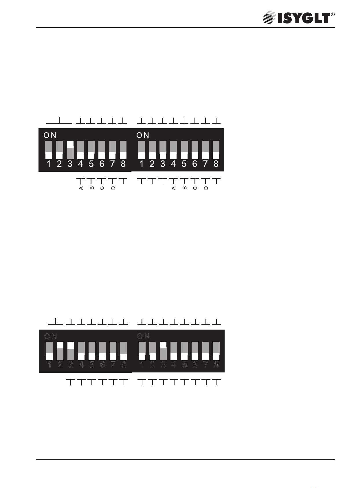
DIP switch DALI operation
Mode
Channel 1+2 coupled
Dimming channel 1
or total
Dimming channel 2
Reserve
Reserve
Reserve
Reserve
Channel 1+2 separately
DIP switch stand-alone operation
12345678
O N
Mode
U-inputs 1-10V
Channel 1+2 coupled
1-button-dimmer
Reserve
U-inputs 0-10V
Channel 1+2 separately
Analog 0(1)-10V
Reserve
1 2 3 4 5 6 7 8
O N
U-inputs 1-10V
U-inputs 0-10V
C
A
B
D
C
A
B
D
Dimming channel 1
or total
Dimming channel 2

Seebacher GmbH www.seebacher.de Phone: +49 (0) 80 41 / 77 77 6
Marktstrasse 57, 83646 Bad Tölz info@seebacher.de Fax: +49 (0) 80 41 / 77 77 2
8
Settings
Function Mode
U-input 1-10V Control via digital potentiometer from switch manufacturer, or 1-10V dimmer coupler. (It behaves as an ECG
of fluorescent light bulb - the 10V for the 1-10V dimming provides the dimmer.)
U-input 0-10V Control via external control e. g. PLC with 0-10V
(0-10V voltage comes from the PLC)
A/B/C/D See table below
Reserve Not used in this operating mode
Channel 1+2 coupled The dimmer operates 1-channel, power 1x 1400W
Jumper between outputs LD1 and LD2 is required
Channel 1+2 separately The dimmer operates 2-channel, power 2x 700W
The outputs LD1 and LD2 must not be jumpered
1-button-dimmer Control by means of standard buttons on the terminals UE1 and UE2 against GND
Short press = On/Off, long press = dimming
Analog 0(1)-10V Control analog
In this position the DIP switches 3 are enabled for selection 0-10V or 1-10V
Operation mode setting when using DALI and stand-alone mode with DIP switches „A“ to „D“
DIP A DIP B Operation mode
OFF OFF Automatic change of operation mode, the start value can be defined in the PC software on the „General“ tab
ON OFF Trailing edge
OFF ON Leading edge
ON ON NonDim
DIP C DIP D Setting dimming characteristics such as minimum and maximum values, curves etc.
(see PC software for UD-700-X2)
OFF OFF Parameter of 1st column, curve P-linear („General“ in PC software)
ON OFF Parameter of 2nd column, curve DALI („General“ in PC software)
OFF ON Parameter of 3rd column, curve t-linear („General“ in PC software)
ON ON Parameter of 4th column, curve Ueff-linear (with setting for preheating for ESL; „General“ in PC software)
Seebacher GmbH www.seebacher.de Phone: +49 (0) 80 41 / 77 77 6
Marktstrasse 57, 83646 Bad Tölz info@seebacher.de Fax: +49 (0) 80 41 / 77 77 2
9
10. Technical data
Type UD-700-X2-DALI
Article no. 80026504
Power supply 230V / 45 to 65 Hz
Fuse protection 1 x 230V circuit breaker or GL fuse 10A
Output 2 x 230V short-circuit proof, 10W to 700W per channel
Power loss <0.5W...6W (standby...full load) per channel - total 12W at 2x700W load
Please provide sufficient ventilation of the switch cabinet or housing.
1 (0)-10V Sink current at 1-10V = 0,54mA
Source current at hardware option 0-10V = 0.14mA to 71kOhm
Isolation voltage 3500V (ISYGLT-BUS / network)
Short-circuit protection Electrical overload prevention by measuring current, short-circuit shutdown within 10 milliseconds
Subnet (RS-485) max. 5.6V limited by Z diodes
Dimensions WxHxD 106x90x59mm DIN rail mounting (6 HP)
Weight 300g
Connection Screw terminals 1.5mm² pluggable
Operating temperature -10°C to +45°C
-> at +50°C max. 60% connectable power
-> at +55°C max. 50% connectable power
-> at +60°C max. 30% connectable power
Storage temperature -25°C to +70°C
Humidity 0-85% r.h., not condensing
Protection type IP30
Protection class I
CE mark yes
10.1. Pin assignment
7-pole connector (left)
GND Reference potential (ground) for the voltage inputs (0-10V) and BUS RS-485 (internally jumpered with the seventh terminal)
UE1 Control voltage input for the dimmer output LD1 (emergency function)
UE2 Control voltage input for the dimmer output LD2 (emergency function)
+10V Voltage supply for external potentiometer(s)
Res.
D+ DALI
D- DALI
6-pole connector (right)
LD1 Dimmer 1 load output 0-230V max. 700W/VA leading edge / trailing edge
LD2 Dimmer 2 load output 0-230V max. 700W/VA leading edge / trailing edge
L Mains voltage 230V (45Hz-65Hz)
N Neutral conductor
N Neutral conductor
PE Protective conductor

Seebacher GmbH www.seebacher.de Phone: +49 (0) 80 41 / 77 77 6
Marktstrasse 57, 83646 Bad Tölz info@seebacher.de Fax: +49 (0) 80 41 / 77 77 2
10
View

Seebacher GmbH www.seebacher.de Phone: +49 (0) 80 41 / 77 77 6
Marktstrasse 57, 83646 Bad Tölz info@seebacher.de Fax: +49 (0) 80 41 / 77 77 2
11
11. Wiring diagram
DALI 2x700W
B6A
N
.
PE
1
.
N PEN PE
low voltage magnetic transformer
low voltage electronic transformer /
dimmable ECG
high voltage halogen
optional:
external voltage control
channel 1
channel 2
leading edge
trailing edge
Suited for
trailing or
leading edge
trailing or
leading edge
max. 700W max. 700W
Sample: controlled by DALI 2x700W
0(1)-10V
0(1)-10V
0V
DALI
DALI
N
PE
D1
D2
Art.-Nr.:
RLC
max. 2x700VA
UD-700-X2-DALI
1234567812345678
OFF
ON
80026504
L
N
D+
D-
LD1
LD2
N
UE1
UE2
GND
+10V
e.g emergency function
trailing or
leading edge

Seebacher GmbH www.seebacher.de Phone: +49 (0) 80 41 / 77 77 6
Marktstrasse 57, 83646 Bad Tölz info@seebacher.de Fax: +49 (0) 80 41 / 77 77 2
12
DALI 1x1400W
max.1400W
PE
D1
D2
Art.-Nr.:
RLC
max. 2x700VA
UD-700-X2-DALI
1234567812345678
OFF
ON
80026504
L
N
D+
D-
LD1
LD2
N
UE1
UE2
GND
+10V
DALI
DALI
N
channel 1
0(1)-10V
0V
Sample: controlled by DALI 1x1400W
B6A
N
.
PE
1
.
optional:
external voltage control
e.g emergency function
leading edge
trailing edge
Suited for
trailing or
leading edge
trailing or
leading edge
N PE
low voltage magnetic transformer
low voltage electronic transformer /
dimmable ECG
high voltage halogen

Seebacher GmbH www.seebacher.de Phone: +49 (0) 80 41 / 77 77 6
Marktstrasse 57, 83646 Bad Tölz info@seebacher.de Fax: +49 (0) 80 41 / 77 77 2
13
Stand-alone 1-10V and 1-button-dimming (without BUS)
1-10V Poti
1-10V Poti
option 1-10V potentiometer
option 1-button dimmer
DIP switches
please use the datasheet
Sample: 1-10V and 1-button dimming
PE
D1
D2
Art.-Nr.:
RLC
max. 2x700VA
UD-700-X2-DALI
1234567812345678
OFF
ON
80026504
L
N
D+
D-
LD1
LD2
N
UE1
UE2
GND
+10V
N
max.700W max.700W
B6A
N
.
PE
1
.
leading edge
trailing edge
Suited for
trailing or
leading edge
trailing or
leading edge
trailing or
leading edge
N PE
N PE
low voltage magnetic transformer
low voltage electronic transformer /
dimmable ECG
high voltage halogen

Seebacher GmbH www.seebacher.de Phone: +49 (0) 80 41 / 77 77 6
Marktstrasse 57, 83646 Bad Tölz info@seebacher.de Fax: +49 (0) 80 41 / 77 77 2
14 Misprints and technical changes reserved.
Stand-alone potentiometer 10kOhm (without BUS)
N PE
PE
D1
D2
Art.-Nr.:
RLC
max. 2x700VA
UD-700-X2-DALI
1234567812345678
OFF
ON
80026504
L
N
D+
D-
LD1
LD2
N
UE1
UE2
GND
+10V
Sample: Potentiometer 10kOhm
A
E
S
A
E
S
option potentiometer 10kOhm
max.700W max.700W
N PE
N
B6A
N
.
PE
1
.
DIP switches
please use the datasheet
leading edge
trailing edge
Suited for
trailing or
leading edge
trailing or
leading edge
trailing or
leading edge
10kOhm
10kOhm
low voltage magnetic transformer
low voltage electronic transformer /
dimmable ECG
high voltage halogen
This manual suits for next models
1
Table of contents


