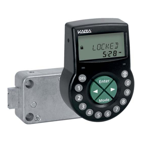
Smartlock Digital Axessor USB User manual


Operating Manual A21-L-02-02_Axessor_USB_Manual_EN.pdf
Subject to change without prior notice Page 3
Axessor USB
System overview - Electronic safe lock Axessor USB
3
2
5
4
1
11
12
10
9
7
8
6
15
14
13
12345678
Type
Part No.
Serial No.
Version
Certs.
Axessor
XXXXXXXXXX
XXXXX.XXXXXX/XXX
xxxxx.xx 2008
VdS
16
18
19
17
20

A21-L-02-02_Axessor_USB_Manual_EN.pdf Operating Manual
Page 4 Subject to change without prior notice
Axessor USB
Input Unit
1 Housing
2 Connection cable to lock unit
3 Interface (USB) for PC connection
4 <ENTER>key(enter,conrm)
5 <INFO/ESC> key (activate info display or escape/go back to upper level)
6 Batterycompartment
7 <MODE>key(activateProgrammingMode)
8 <LEFT> and <RIGHT> key (directional keys to navigate)
9 <0>...<9>(numerickeys0...9)
10 <DEL> key (delete, close lock)
11 LCD (liquid crystal display)
12 Buzzer
Lock
13 Lock housing
14 Terminalblocks(Inputs/Outputs)
15 Pin for cable tie holder
16 ConnectingsocketX1(cablefrominputunit)andX2(externalpowersupply)
17 Warranty seal
18 Type label
19 VdS-label (protects spring bolt setting screw)
20 External power supply (option)

Operating Manual A21-L-02-02_Axessor_USB_Manual_EN.pdf
Subject to change without prior notice Page 5
Axessor USB
TABLE OF CONTENT
1 Introduction 9
1.1 To the very beginning 9
1.2 Notes regarding the Operating Manual 9
1.2.1 Validity 9
1.2.2 Target group 9
1.2.3 Limitation 9
1.2.4 Supplementarydocumentation 9
1.2.5 Symbolsusedinthisoperatingmanual 10
1.2.6 Textmarking 10
2 Safety and Environment 11
2.1 General 11
2.2 Qualicationofpersonnel 11
2.3 Prohibitedmodicationstotheunit 11
2.4 Environment 11
3 Product overview 12
3.1 Product description 12
3.2 Field of application 13
3.3 Intended use 13
4 Installation 14
4.1 Importantinformationpriortotheinstallation 14
4.2 Upacking and checking the delivery 14
4.3 Installing the Input Unit 15
4.4 Installing the lock 20
4.5 Performwiringcheckafterlockinstallation 22
4.6 External connections at the lock 23

A21-L-02-02_Axessor_USB_Manual_EN.pdf Operating Manual
Page 6 Subject to change without prior notice
Axessor USB
5 Operating 25
5.1 OperatinganddisplayelementsoftheInputUnit 25
5.2 Operatingmodes 26
5.2.1 Normaloperatingmode 26
5.2.2 Programmingmode 26
5.2.3 Informationmenu 26
5.3 Buzzer signals 27
5.4 Statusmessages 27
5.4.1 Locked 27
5.4.2 Open 27
5.4.3 Immediatetimelock 27
5.4.4 Timelock(Weekly) 28
5.4.5 Timelock(Holiday) 28
5.4.6 TimeDelay 28
5.4.7 ConrmationafterelapseofTimeDelay 28
5.4.8 Enter second code (Dual Mode activated) 29
5.4.9 Penalty after wrong trials 29
5.4.10 RemoteDisabling 29
5.4.11 Identicationwithdeniedcode 29
5.4.12 Thebatterycompartmenthasbeenopened 30
5.4.13 ConnectedwithProgrammingSoftware 30
5.4.14 External power supply available 30
5.5 Access Codes 31
5.5.1 Codehierarchyandcodeformats 31
5.5.2 Code types 31
5.5.2.1 Master Code 32
5.5.2.2 Manager Codes 33
5.5.2.3 User Codes 33
5.5.2.4 Courier Code 33
5.5.3 Shelve Function 34
5.5.4 Duress Code 34
5.6 Code entry 35
5.7 Opening procedure 36
5.8 Closing procedure 38

Operating Manual A21-L-02-02_Axessor_USB_Manual_EN.pdf
Subject to change without prior notice Page 7
Axessor USB
6 Programming Mode 39
6.1 Operatingtheprogrammingmode 39
6.1.1 Activatingtheprogrammingmode 39
6.1.2 NavigatingintheProgrammingMode 40
6.1.3 ModifyandsavesettingsintheProgrammingMode 40
6.1.4 ExitingtheProgrammingMode 41
6.2 Menu overview 42
6.3 Access rights 43
6.4 Programming 44
6.4.1 Menu TIME 44
6.4.1.1 Settingthetime-submenuTIME 44
6.4.1.2 Settingthetime-submenuDATE 45
6.4.1.3 Settingthetimeformat-submenuAM/PM 46
6.4.2 Menu PROG 47
6.4.2.1 ConguringWeeklyLockingPeriods-SubmenuWEEKLY 47
6.4.2.1.1 Adding a Weekly Locking Period 47
6.4.2.1.2 Modifying an existing Weekly Locking Period 48
6.4.2.1.3 Deleting an existing Weekly Locking Period 49
6.4.2.2 ActivatinganImmediateTimeLock-SubmenuIMM-TL 50
6.4.2.3 ConguringHolidayLockingPeriods-SubmenuHOLIDAY 51
6.4.2.3.1 Adding a Holiday Locking Period 51
6.4.2.3.2 Modifying an existing Holiday Locking Period 52
6.4.2.3.3 Deleting an existing Holiday Locking Period 53
6.4.3 MenuDELAY 54
6.4.3.1 Setting/DeactivatingTimeDelays-SubmenusDELAY1...2 54
6.4.3.2 ConguringtheConrmationWindow-SubmenuCNFWIN 56
6.4.4 Menu CODE 57
6.4.4.1 ChangingtheMasterCode-SubmenuMASTER 57
6.4.4.2 SettingManagerCodes-SubmenuMANAGER 58
6.4.4.3 SettingUserCodes-SubmenuUSER 59
6.4.4.4 SettingtheCourierCode-SubmenuCOURIER 60
6.4.4.5 Reset the whole AxessorUSBsafelocksystemto
factorydefaults-SubmenuSHELVE 61
6.4.4.6 Modifying a code 62
6.4.4.7 Deleting a code 63
6.4.5 Menu MISC 64
6.4.5.1 Activating/DeactivatingCodeDenial-SubmenuCDEDEN 64
6.4.5.2 Activating/DeactivatingRemoteDisabling-
SubmenuRMT-DIS 65
6.4.5.3 Activating/Deactivating Duress Code function -
SubmenuDURESS 66
6.4.5.4 Activating/DeactivatingDualMode-SubmenuDUAL 67
6.4.5.5 Settingthedisplaylanguage-SubmenuLANG 68

A21-L-02-02_Axessor_USB_Manual_EN.pdf Operating Manual
Page 8 Subject to change without prior notice
Axessor USB
7 Servicing 69
7.1 Cleaning 69
7.2 Replacing the batteries 69
7.3 CustomerService 70
7.4 Spare parts and accessories 71
8 Error messages 72
9 Technical data 75
9.1 Functions 75
9.2 Electronics 77
9.3 Mechanics 78
9.4 ApprovalsandCerticates 79
9.5 Factory settings 80

Operating Manual A21-L-02-02_Axessor_USB_Manual_EN.pdf
Subject to change without prior notice Page 9
Axessor USB
1 Introduction
1.1 To the very beginning
We thank you for having opted for the electronic safe lock Axessor USB.
The electronic safe lock Axessor USB incorporates the latest technical advances
andmeetsallrecognizedsafetystandards.Nevertheless,improperuseofthe
electronicsafelockAxessorUSBmayresultinimpairmentofmaterialassets.
Toensureasafe,proper,andeconomicaloperationoftheelectronicsafelock
AxessorUSB,pleaseobserveandcomplywithallinformationandsafetyinstruc-
tions contained in the present Operating Manual as well as the instructions given
inthemanualsforthecomponentsusedinconjunctionwiththesafelock.
Ifyouhavequestions,whicharenotorinsufcientlyansweredinthisOperating
Manual, please contact your supplier. They will be glad to assist you.
1.2 Notes regarding the Operating Manual
1.2.1 Validity
This Operating Manual describes the electronic safe lock Axessor USB.
1.2.2 Target group
This Operating Manual addresses itself to well trained personnel which is in
chargewiththeinstallation,thecommissioning,theoperation,theservicingand
the trouble shooting of the electronic safe lock Axessor USB.
1.2.3 Limitation
ThisOperatingManualisrestrictedtotheinstallation,commissioning,operation,
servicing and trouble shooting of the electronic safe lock Axessor USB.
TheoptionalAS284ProgrammingSoftwareisonlydescribedinsofarasthisis
necessaryforproperoperationofthesafelock.FurtherinformationontheAS
284ProgrammingSoftwarecanbeobtainedinthehelpfunctionofthesoftware.
1.2.4 Supplementary documentation
ThisoperatingmanualissupplementedwiththeAxessorUSBQuickReference
Guide.

A21-L-02-02_Axessor_USB_Manual_EN.pdf Operating Manual
Page 10 Subject to change without prior notice
Axessor USB
1.2.5 Symbols used in this operating manual
Thefollowingsymbolsareusedinthisoperatingmanualtodirectyourattention
onparticularsituation,e.g.toindicateahazardoussituation,requirementswhich
mustbemet,etc.:
Warning!
Indicatesahazardwhichcancausedamagetotheunitorhaveaseriouseffect
on the function or use of the unit if unobserved.
Important!
Indicatesimportantinformationwhichmustbeobservedduringthedescribed
procedure.
Note!
Indicatesnotes,informationorpointers,whichfacilitateworkorprovideadditional
backgroundinformationorpointoutspecicdetails.
Requirement!
Indicatesrequirementsthatmustbemetfortheexecution,activation,modica-
tionordeletionofthedescribedfunction.Theserequirementsmustbemetbefore
proceeding.
AS 284 Programming Software
ReferstotheAS284ProgrammingSoftware(optionallyavailable),whichallows
additional settings and functions.
1.2.6 Text marking
• Thecharacter„“standsfor„see“,„referto“or„alsoconsult“
Sample:foradescriptionofAccessCodeHierarchyCode hierarchy and
code formats on page 31).
• Textappearingonthedisplayismarkedincapitalsandsetintoquotation
marks(sample:„LOCKED“).
• Keystobeusedaremarkedinboldcapitalsandsetintoanglebrackets:
<DEL> = Delete key
<NUMERIC> =Numerickeys0…9
<INFO/ESC> =Information/Escapekey
<ENTER> = Enter key
<MODE> = Mode key
<LEFT> = Left arrow key
<RIGHT> = Right arrow key

Operating Manual A21-L-02-02_Axessor_USB_Manual_EN.pdf
Subject to change without prior notice Page 11
Axessor USB
2 Safety and Environment
2.1 General
EverypersonworkingwiththeAxessorUSBmusthavereadandunderstoodthe
operatingmanualbeforecarryingoutanywork.
Knowingandunderstandingthecontentsoftheoperatingmanualisabasic
requirementforprotectingthepersonnelagainstanykindofdanger,toprevent
faulty operation, and to operate the unit safely and correctly.
2.2 Qualication of personnel
Allactionsdescribedinthepresentoperatingmanual(installation,commis-
sioning,operation,etc.)mustbecarriedoutonlybywelltrainedandsufciently
qualiedpersonnel.
Forsafetyandwarrantyreasonsanyactionbeyondthescopeofthismanual
mustbecarriedoutonlybyqualiedpersonnelauthorisedbythemanufacturer.
ItisassumedthatallpersonsworkingwiththeAxessorUSBarefamiliarand
complywiththeappropriateregulationsonworksafetyandthepreventionof
accidents.
2.3 Prohibited modications to the unit
ModicationsontheelectronicsafelockAxessorUSBareexplicitlynotrecom-
mended,itmayvoidwarrantyandimpairthesecurityandsafetyoftheunit.
Forthereplacementofdefectivecomponentsuseexclusivelyoriginalaccessories
andsparepartsavailablefromyoursupplier.
2.4 Environment
Packingandconsumablematerial(e.g.batteries)mustbedisposedofand/or
recycled according to the local regulations.
Attheendoftheservicelifetheunitanditscomponentsmustbereturnedtothe
manufacturerortoacollectingpointfordisposalorrecyclingaccordingtothe
local regulations.
In case of doubt please contact your supplier.

A21-L-02-02_Axessor_USB_Manual_EN.pdf Operating Manual
Page 12 Subject to change without prior notice
Axessor USB
3 Product overview
3.1 Product description
TheelectronicsafelockAxessorUSBisanintelligentmotor-boltlockwithinte-
gratedterminalsusedforinstancetoconnecttoanalarmcentre.Itfeaturesa
widerangeoffunctionalities,suchasacodehierarchywithUserGroupmanage-
ment,CourierCode,DualMode,DuressCode,TimeDelay,TimeLockfunctions,
RemoteDisablingandCodeDenial.Theoperationandtheprogrammingisdone
via the Input Unit.
TheelectronicsafelockAxessorUSBmayalsobeconguredwiththeAS 284
Programming Software (optionally available). This gives access to an even
enhancedfunctionalityandallowscustomer-tailoredsolutionstoalmostevery
extent.
Unit conguration standard version
In its standard version the electronic safe lock Axessor USB is battery powered
andconsistof:theinput unit, the lock and the connection cable. The lock
includes2inputsand2outputs(assignmentExternal connections at the lock
on page 23).Optionally,anexternalpowersupply(6VDC/500mA)canbecon-
nectedtooneofthelocksockets„X1“or„X2“.
Only use the original Axessor USB power supply. Even if the external power
supplyisconnected,thebatteriesmustremaininthebatterycompartmentatall
times.Theyaremainlybutnotexclusivelyusedincaseofapowerfailure.Only
use non rechargeableAAAlkalineorAALithiumbatteries.
12345678
Type
Part No.
Serial No.
Version
Certs.
Axessor series
XXXXXXXXXX
XXXXX.XXXXXX/XXX
90048.xx
2007
VdS

Operating Manual A21-L-02-02_Axessor_USB_Manual_EN.pdf
Subject to change without prior notice Page 13
Axessor USB
3.2 Field of application
The electronic safe lock Axessor USB provides a wide range of functions for ap-
plicationsinthehighsecuritysector.Theypermitprogrammingofvariouscodes
andcodecombinations,timerelatedfunctionsaswellasstorageandrecallofa
detailed event log (Audit Trail).
Theprogrammingcanbedoneviatheinputunitorbyconnectingacomputer
runningtheAS284ProgrammingSoftwaretotheinputunitviaUSBcable.
This electronic safe lock is especially suitable for applications where high security,
multipleusers,traceabilityandexibilityarerequired.
3.3 Intended use
TheelectronicsafelockAxessorUSBservestoblockandreleasethemechanical
blocking point of a safe, vault, data cabinet, ATM etc. which is usually activated
manuallybyaboltwork.TheelectronicsafelockAxessorUSBcanbeemployed
insteadofamechanicalcombinationorkeylock.Applicableregulationsand
standards have to be observed.
Enabling(lockopening)isonlyperformeduponentryofoneorseveralcodeson
theInputUnit.Theopeningprocedurecanalsobemadedependentontimefunc-
tions and/or external signals.
TheelectronicsafelockAxessorUSBmayonlybeemployedandoperatedinac-
cordancewithitsintendeduse–blockingandreleasingthemechanicalblocking
pointsofabovementionedequipment.Anyothertypeofapplicationisexplicitly
notrecommended.
The electronic safe lock Axessor USB is designed for indoor applications
(environmentallyprotectedareas)–theyarenotsuitablefordirectexposureto
environmentalimpact.
Operationoftheequipmentintheintendedmannerrequiresthatalltheinforma-
tioninthisoperatingmanualisobserved.

A21-L-02-02_Axessor_USB_Manual_EN.pdf Operating Manual
Page 14 Subject to change without prior notice
Axessor USB
4 Installation
4.1 Important information prior to the installation
Warning!
Please observe the following:
•Compliancetodescribedsequenceisanecessity.Improperassemblyordif-
ferentsequencemaycausedamagetotheunit!
•Toavoidanydamagemakesuretokeepcablesawayfrommovingparts!Do
notleadcablesoversharpedges!
•Donotclosethesafedooruntilallinstallationstepshavebeencompleted
successfully!
Important!
Please observe the following:
•Removalofordamagetothewarrantyseal(System overview - Electronic
safe lock Axessor USB on page 3,item17)voidswarranty!
•Themountingscrewsmustbesecuredagainstloosening,e.g.byusing
screwcement,suchasLOCTITE243(medium,blue).
•RemovalofordamagetotheVdSlabel(System overview - Electronic safe
lock Axessor USB on page 3,item19)voidsVdSapproval!
•Thelockmustnotbemounteddirectlybehindleadthroughs!Clogorsecure
leadthroughscorrespondingly.Asuitablecoverplatetoprotectthelockis
availablefromyoursupplier(52xDPULdrillingprotectionplate).
4.2 Upacking and checking the delivery
Unpackthedeliveryandcheckthecontentofcompleteness.
The Axessor USB deliveryincludes:
• InputUnit
• Lock
• Connectioncable
• Plasticbagcontaininginstallationmaterial
• 3batteriesAA-size
• Instructionleaetwithfurtherinformationandreferencetohomepage
The optional computer software packagesinclude:
• AS284-USBW:CD,USBcable,1xOperatordongle

Operating Manual A21-L-02-02_Axessor_USB_Manual_EN.pdf
Subject to change without prior notice Page 15
Axessor USB
4.3 Installing the Input Unit
Mounting the base plate
1. Markeitherthexationbores3 and 5 or 2 and 4 plus bore 1 (recommend-
ed).Alsomarkoneofthetwobores6(cable leadthrough) Do so according to
theillustrationbeloworbyusingthetemplate(TemplateInputUnitonpage
83).
2. Drillthe3xationboresØ3.2x14mmandthecableleadthroughbore
Ø10mm.Removeburrs.TapM4threadsintothe3xationbores.
40
41.3
55
10
4 x M4
1
3
2
6
10
6
5
4
193
90

A21-L-02-02_Axessor_USB_Manual_EN.pdf Operating Manual
Page 16 Subject to change without prior notice
Axessor USB
3. Removethe3screwsonthebottomofthecover(1atthebatterycompart-
ment,2atthehousing).Lift-offthecoverfromthebaseplate,thencarefully
removethebatterycompartment.
4. FixthebaseplatewiththeenclosedspecialM4x12at-headscrewstothe
door.TheInputunitmustbexedtothedoorwithatleasttwooppositely
positioned screws. The third screw (Pos. 1) is recommended.

Operating Manual A21-L-02-02_Axessor_USB_Manual_EN.pdf
Subject to change without prior notice Page 17
Axessor USB
Connecting the cables
5. CarefullyleadtheenclosedconnectioncablethroughtheØ10mmboreinthe
doorandcarefullydrawittowardsthelockchamber.
6. Mountbatterycompartmentinplace.Then,carefullyleadthebatterycable
throughstrainreliefguidesofthebatterycompartmentandthebaseplate.
Make sure not to squeeze the cable!
Finallycheckforfreemovabilityofthebatterycompartment.
Make sure the spiral cable lays at when moving the battery compart-
ment (i.e. the cable does not move in other directions when extended
and compressed).

A21-L-02-02_Axessor_USB_Manual_EN.pdf Operating Manual
Page 18 Subject to change without prior notice
Axessor USB
7. Position the cover on top of the base plate in an angle >90°.
8. Plugthebatterycableintothe2poleconnectionterminalandtheconnection
cableintothe6poleconnectionterminal.
Check correct position of the plugs before connecting them. Do not
use excessive force to plug-in, but make sure that proper connection is
given.
Battery
Lock

Operating Manual A21-L-02-02_Axessor_USB_Manual_EN.pdf
Subject to change without prior notice Page 19
Axessor USB
Mounting the cover
9. Engage the cover at notch on top of base plate.
10.Slowlyipdownthecoverontothebaseplatewhilecarefullypullingthecon-
nectioncabletowardsthelockchamber;leavesomespareloop.
Make sure that cables are not squeezed. Checkbatterycompartmentfor
freemovability:carefullypushthebatterycompartmentintoplace,thenslide
it out again.
11. Fix the cover on the base plate using two M3x6 countersink screws.
12.Checkbatterycompartmentforpropermovability:carefullypushthebattery
compartmentintoplace,thenslideitoutagain
Do not insert the batteries and do not x the battery compartment
screw yet.

A21-L-02-02_Axessor_USB_Manual_EN.pdf Operating Manual
Page 20 Subject to change without prior notice
Axessor USB
4.4 Installing the lock
Mounting the lock
1. Markthe3xationbores(A)accordingtotheillustrationbeloworbyusing
thetemplate(TemplateLockonpage84).
2. DrilltheboresØ5mm.RemovetheburrsandtapM6threadsintothebores.
3. Mount the lock with the 3 enclosed M6x10 screws (equivalent Inch screws
maybeusedinstead).
Make sure that the screw heads rest on the base of the shouldered
bore! Make sure to keep the space underneath the lock free for a re-
locker system or the connection cable!
4. Ifthelockistobeoperatedinspringboltfunction,removetheretainerscrew
(B) underneath the VdS label.
Be aware, that this operating mode voids VdS approval!
B
12345678
41.3
66.7
3 x Ø5
7.9
11.5
15
2 x M4
13
2.5
25.2
7.8
Type
Part No.
Serial No.
Version
Certs.
AXESSOR
XXXXXXXXXX
XXXXX.XXXXXX/XXX
xxxxx.xx 2008
VdS
A A
A
Table of contents
Other Smartlock Digital Lock manuals
Popular Lock manuals by other brands

Yale
Yale Real Living YRD240 Installation & programming instructions
CAMDEN
CAMDEN CX-92S TDS Series installation instructions
AmazonBasics
AmazonBasics B07T5MMZ46 quick start guide
Lockton
Lockton MDL2100 instructions

COMPX
COMPX Timberline CB-240 instruction sheet
Lee & Plumpton
Lee & Plumpton Signature Espagnolette Lock System Aassembly Instructions
