smartmicro TRUGRD User manual

TRUGRD_Stream_User_Manual_USA_CAN_200MHz.docx Version 1 IPage 1 of 14 IFebruary 8, 2021
Project Documentation | TRUGRD Stream User Manual
Project Number:
...
SMS Project Number:
Project Title:
TRUGRD Stream User Manual
Keyw ord( s) :
TRUGRD Stream, radar, sensor
Date:
February 8, 2021
Document:
TRUGRD_Stream_User_Manual_USA_CAN_200MHz.docx
Version:
1

TRUGRD_Stream_User_Manual_USA_CAN_200MHz.docx Version 1 IPage 2 of 14 IFebruary 8, 2021
1 Contents
1Contents.................................................................................................................... 2
2Abbreviations............................................................................................................. 3
3Introduction............................................................................................................... 4
4General description .................................................................................................... 5
4.1 Sensor description................................................................................................ 5
4.2 Transmit Signal.................................................................................................... 5
4.3 General Performance Data.................................................................................... 5
4.4 Software and Firmware Version ............................................................................ 6
5Hardware .................................................................................................................. 7
5.1 TRUGRD Stream Sensor View ............................................................................... 7
5.2 Sensor Dimensions............................................................................................... 8
6Cables and Connectors ............................................................................................... 9
6.1 Sensor connector ................................................................................................. 9
6.2 CAN data interface ............................................................................................... 9
6.3 CAN-Settings ..................................................................................................... 10
6.4 RS485 data interface.......................................................................................... 11
7Designated Use........................................................................................................ 12
8Compliance.............................................................................................................. 13
8.1 Declaration of Conformity for USA....................................................................... 13
8.1.1 FCC-Label.................................................................................................... 13
8.2 Declaration of Conformity for Canada .................................................................. 14
8.2.1 Declaration of Conformity in English.............................................................. 14
8.2.2 Déclaration de conformité en francais ........................................................... 14
8.2.3 Industry Canada (IC) Label........................................................................... 14

TRUGRD_Stream_User_Manual_USA_CAN_200MHz.docx Version 1 IPage 3 of 14 IFebruary 8, 2021
2 Abbreviations
ADC Analog-to-Digital Converter
AFE Analog Front-End
CAN Controller Area Network
DSP Digital Signal Processing; Digital Signal Processor
EEPROM Electrically Erasable Programmable Read-only Memory
FMCW Frequency Modulated Continuous Wave
GPIO General Purpose Input Output
MMI C Monolithic Microwave I ntegrated Circuit
RAM Random Access Memory
RS485 Physical communication layer standard EI A RS-485
SPI Serial Peripheral Interface
SOC System on Chip
UMRR Universal Medium-Range Radar

TRUGRD_Stream_User_Manual_USA_CAN_200MHz.docx Version 1 IPage 4 of 14 IFebruary 8, 2021
3 I ntroduction
This document is a short documentation of the general purpose universal medium range
radar (UMRR) TRUGRD Stream sensor with type 48 antenna.

TRUGRD_Stream_User_Manual_USA_CAN_200MHz.docx Version 1 IPage 5 of 14 IFebruary 8, 2021
4 General description
4.1 Sensor description
The main task of the UMRR is the detection of any reflectors in the field of view, to measure
the distance, the relative speed and the angle to the shortest reflector (and to other reflectors),
to detect motion and to track (filter) the results over time.
For this general purpose measurement application, range and relative radial speed and the
angle value of each reflector inside the antenna beam are measured and the results are
reported via the communication links cycle by cycle.
4.2 Transmit Signal
The UMRR transmit frequency is in the 24 GHz I SM band (24000 MHz to 24250 MHz) and the
used bandwidth is smaller than 250MHz.
Antenna type 48 consists of 2 TX antennas with same antenna characteristics but different
center position on the board and 8 uniform RX antennas. The TX antenna have a 3dB antenna
beam width of + -34° in azimuth and + -6,5° in elevation. The 8 RX antennas have a 3dB
antenna beam width of + -25° in azimuth and + -7° in elevation. Highest TX antenna sidelobe:
@+ 74°, highest RX sidelobe at + -50°.
Note: max. Gain for TX antenna at azimuth angle + -22°, elevation angle 0°. The RX antennas
have max. gain at boresight.
Gain RX: 11.1 dBi.
The device uses different FMCW transmit signal waveforms for distance and speed
measurement.
4.3 General Performance Data
After power up or reset, the sensor readings are within specified performance within < 30
seconds. I n Table 4-1 the general performance data is given.

TRUGRD_Stream_User_Manual_USA_CAN_200MHz.docx Version 1 IPage 6 of 14 IFebruary 8, 2021
Table 4-1: General performance data
Environmental
Ambient Temperature
-34 ... + 74
degree C
Shock
100
grms
Vibration
14
grms
IP
67I
Pressure / Transport
altitude
0…10.000
m
Mechanical
Weight
1580
g
Dimensions
See 5.2
Housing Identification
07
Antenna Identification
30
DSP Board Identification
12
General
Power Supply
7 ... 32I I
12II I
V DC
W
Frequency Band
24.0…24.25
GHz
Bandwidth
< 250
MHz
Max. Average Transmit
Power (EI RP)
< 12.7
dBm
Interfaces
CAN V2.0b
RS485 full duplex
10/ 100 Ethernet
Connector
12 Pin plug Hirose LF10WBRB-12PD
CAN,
Power,
RS485,
Eth.
IIP 67 only when connector or cap attached.
II measured at connector, min. voltage slew rate 500V/ s or max. voltage rise time 15ms; supply source impedance
0.5Ohms.
III Typical value 9W @20°C, may slightly increase over temperature.
4.4 Soft ware and Firmw are Version
The software in the TRUGRD Stream has the version 6.

TRUGRD_Stream_User_Manual_USA_CAN_200MHz.docx Version 1 IPage 7 of 14 IFebruary 8, 2021
5 Hardware
5.1 TRUGRD Stream Sensor View
An example picture of a TRUGRD Stream sensor is shown in the figures below.
Figure 5-1: Housing of TRUGRD Stream front
Figure 5-2: Housing of TRUGRD Stream rear
TRUGRD_Stream_User_Manual_USA_CAN_200MHz.docx Version 1 IPage 8 of 14 IFebruary 8, 2021
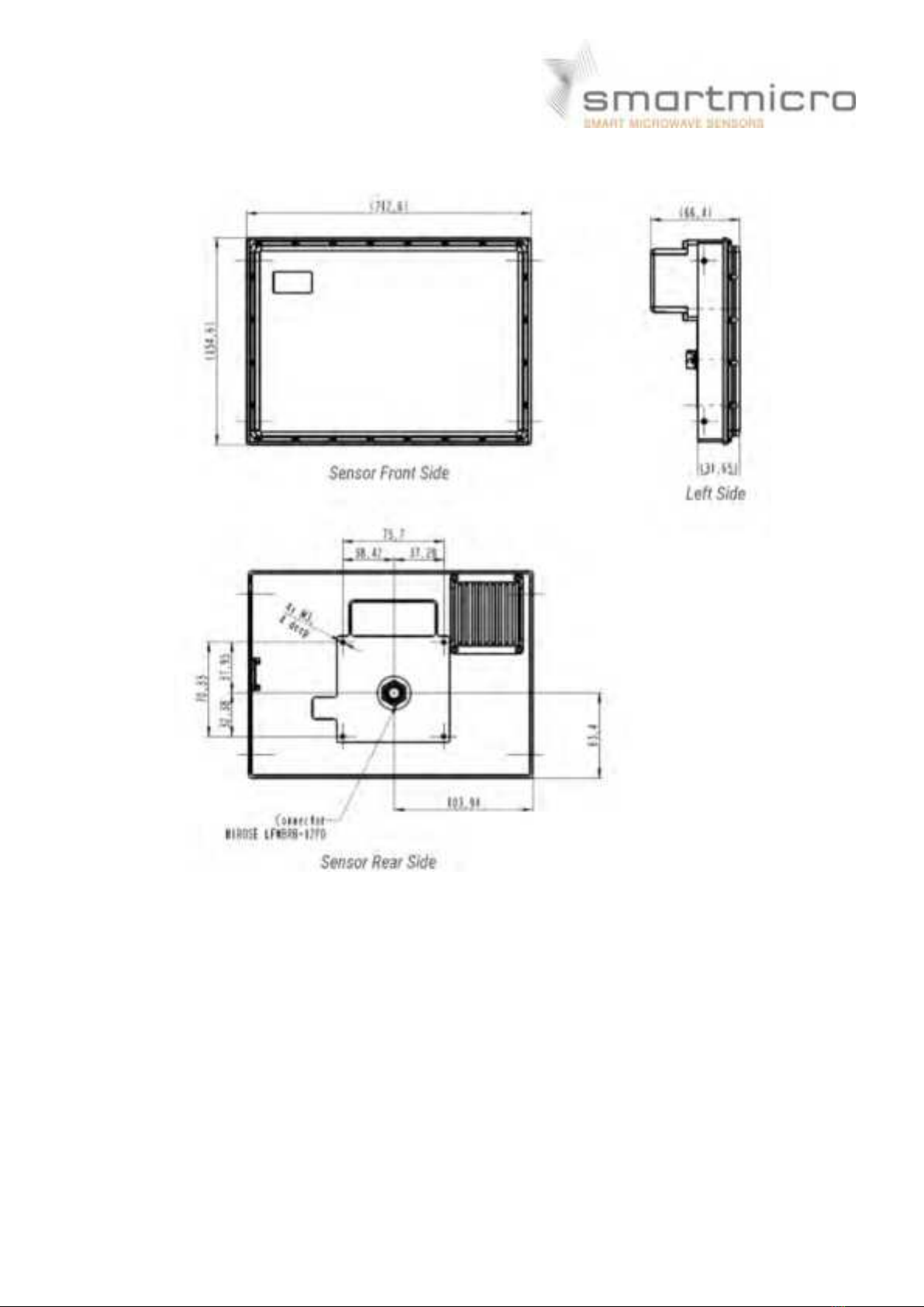
5.2 Sensor Dimensions
All values given in mm.
Figure 5- 3: Dimensions of TRUGRD Stream Sensor
TRUGRD_Stream_User_Manual_USA_CAN_200MHz.docx Version 1 IPage 9 of 14 IFebruary 8, 2021
6 Cables and Connectors
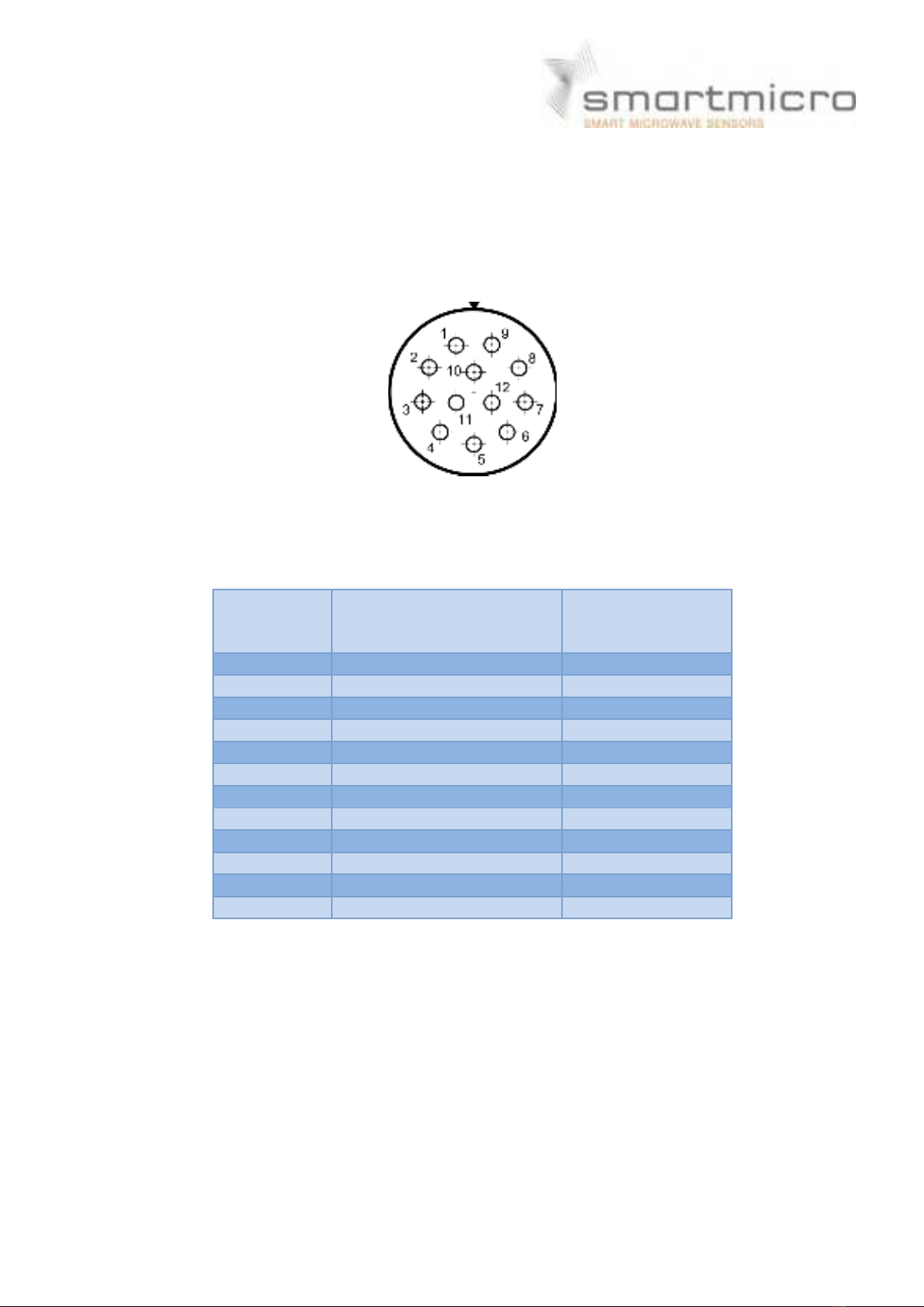
6.1 Sensor connector
The sensor connector is a 12-pin male (plug) circular bayonet type connector (water proof
IP67, series LF10WBRB-12PD, manufacturer Hirose, Japan). A female counterpart (socket),
e.g. LF10WBP-12S, is used to connect to the sensor. The pin numbering of the socket is shown
in Figure 6-1 the pin description is given in Table 6-1.
Figure 6- 1: View on solder cup side of socket ( rear view of female counterpart to be connected to
sensor)
Table 6-1: Sensor connector pin out model
Pin No.
Function
Wire Color
( MEDI type
# KU110C12J002)
1
SENSOR_ETH_TX1_P
gray / red
2
SENSOR_ETH_TX1_N
red / blue
3
SENSOR_RS485_RX_N
pink
4
SENSOR_RS485_RX_P
gray
5
SENSOR_RS485_TX_N
brown
6
SENSOR_RS485_TX_P
white
7
External GND
blue
8
V_SUPPLY
red
9
SENSOR_ETH_TX2_N
black
10
SENSOR_ETH_TX2_P
purple
11
CAN_H
green
12
CAN_L
yellow
Please note that in the standard configuration the sensor has 120 Ohms resistor on board (CAN
bus termination between CAN_L and CAN_H).
For the RS485 data interface there is a 120 Ohms resistor on board of the sensor.
A number of cable sets for initial operation and test purposes are offered by Smartmicro, to
deliver a fast set-up of a sensor system. Among those preconfigured ready-to-run cables as
well as cable stumps (pig tail cables or various lengths) which carry the connector on one side
and open wires on the other.
6.2 CAN data interface
This specification gives a detailed description of the CAN data communication used in the
TRUGRD_Stream_User_Manual_USA_CAN_200MHz.docx Version 1 IPage 10 of 14 IFebruary 8, 2021
UMRR based systems on the sensor CAN. The UMRR is compliant with CAN 2.0B standard.
CAN is a very robust full duplex bidirectional interface.
6.3 CAN-Settings
Baud Rate: 500 kBit/ s or lower
Tseg1: 8
Tseg2: 7
Tsjw: 2 (SJW: synchronization jump width)
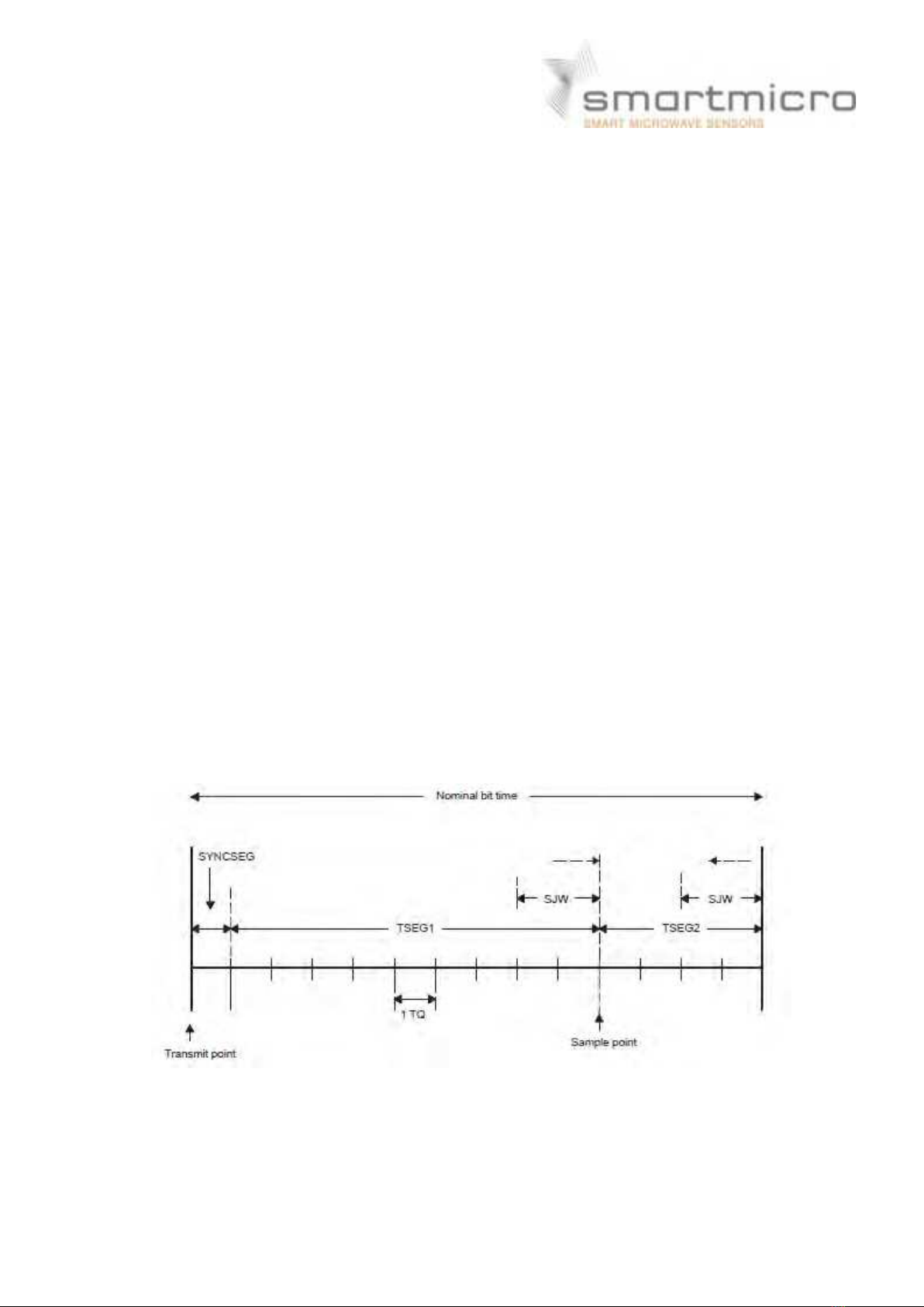
Above values for CAN bit timing are illustrated in Figure 6-2 used in the UMRR radar sensor
(note: the CAN module is integrated in the DSP). For comparison purposes, in Figure 6-3 the
CAN bit timing as defined by the CAN protocol is shown.
The CAN bit timing parts as defined by the CAN protocol (Figure 6-3) can be described as
follows:
•Sync: This part of bit time is used to synchronize the various nodes on the bus. An
edge is expected to lie within this segment. For the UMRR sensor, this segment is
always 1 TIME QUANTUM (TQ).
•Prop: This part of the bit time is used to compensate for the physical delay times
within the network. It is twice the sum of the signal’s propagation time on the bus
line, the input comparator delay, and the output driver delay. For the UMRR sensor,
this segment is programmable from 1 to 8 TIME QUANTA (TQ).
•Phase 1: This phase is used to compensate for positive edge phase error. For the
UMRR sensor, this segment is programmable from 1 to 8 TIME QUANTA (TQ) and
can be lengthened by resynchronization.
•Phase 2: This phase is used to compensate for negative edge phase error. For the
UMRR sensor, this segment is programmable from 2 to 8 TIME QUANTA (TQ) and
can be shortened by resynchronization.
Figure 6-2: CAN bit timing for UMRR sensor

TRUGRD_Stream_User_Manual_USA_CAN_200MHz.docx Version 1 IPage 11 of 14 IFebruary 8, 2021
Figure 6-3: CAN bit timing as defined by the CAN protocol
6.4 RS485 data interface
The RS485 interface from the UMRR sensor has a predefined speed of 115200 baud/ s.
Typical other data rates are between 921.6kBit/ s and 56.7kBit/ s.
The RS485 message payload is identical to the CAN format.

TRUGRD_Stream_User_Manual_USA_CAN_200MHz.docx Version 1 IPage 12 of 14 IFebruary 8, 2021
7 Designated Use
The UMRR general purpose medium range radar is suitable for any application where the
distance to and relative radial speed of large objects has to be measured.
Typical applications are:
Robotics: measure shortest distance to obstacle.
Security: detect motions and measure distance to moving object.
Traffic management: detect moving objects, count those, measure speed and measure
distance to moving object.
Cranes: measure distance to ground.
Aircraft: measure distance to ground.
TRUGRD_Stream_User_Manual_USA_CAN_200MHz.docx Version 1 IPage 13 of 14 IFebruary 8, 2021
8 Compliance
8.1 Declaration of Conformity for USA
This device complies with Part 15 of the FCC Rules. Operation is subject to the following two
conditions:
(1) This device may not cause harmful interference, and
(2) this device must accept any interference received, including interference that may cause
undesired operation.
Usually this is followed by the following FCC caution:
Any changes or modifications not expressly approved by the party responsible for compliance
could void the user’s authority to operate this equipment.
Note:
This equipment has been tested and found to comply with the limits for a Class B digital device,
pursuant to Part 15 of the FCC Rules. These limits are designed to provide reasonable
protection against harmful interference in a residential installation. This equipment generates,
uses and can radiate radio frequency energy and, if not installed and used in accordance with
the instructions, may case harmful interferences to radio communications. However, there is
no guarantee that interference will not occur in a particular installation. I f this equipment does
cause harmful interference to radio or television reception, which can be determined by turning
the equipment off and on, the user is encouraged to try to correct the interference by one or
more following measures:
-Reorient or relocate the receiving antenna
-Increase the separation between the equipment and receiver
-Connect the equipment into an outlet on a circuit different from that to which the
receiver is connected
-Consult the dealer or an experienced radio/ TV technician for help.
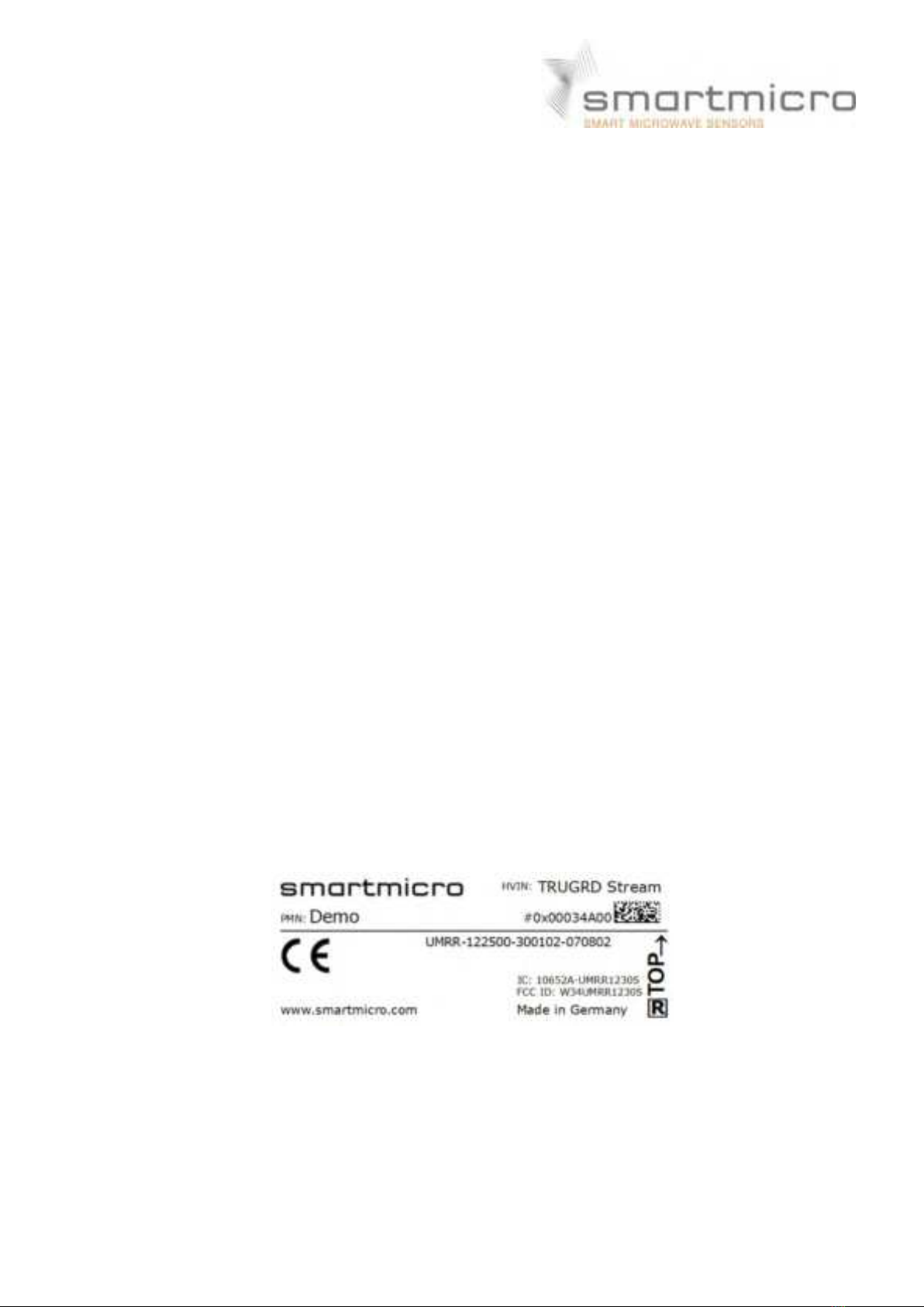
8.1.1 FCC-Label
An example of FCC-label is shown as following:
Figure 8- 1: Sample of FCC Label

TRUGRD_Stream_User_Manual_USA_CAN_200MHz.docx Version 1 IPage 14 of 14 IFebruary 8, 2021
8.2 Declaration of Conformity for Canada
8.2.1 Declaration of Conformity in English
This device complies with I ndustry Canada licence-exempt RSS standard(s).
Operation is subject to the following two conditions:
(1) this device may not cause interference, and (2) this device must accept any interference,
including interference that may cause undesired operation of the device.
IC Radiation Exposure Statement:
This equipment complies with I C RSS-102 radiation exposure limits set forth for an uncontrolled
environment. This equipment should be installed and operated with the minimum distance
20cm between the radiator & your body.
8.2.2 Déclaration de conformité en francais
Le present appareil est conforme aux CNR d’Industrie Canada applicables aus appareils radio
exempts de licence. Léxploitation est autorisée aux deux conditions suivantes: (1) l’appareil ne
doit pas produire de brouillage, et (2) l’utilisaeur de l’appareil doit accepter tout brouillage
radioélectrique subi, même si le brouillage est susceptible d’en compromettre le
fonctionnement.
DÉCLARATION D’EXPOSI TI ON AUX RADIATI ONS
Cet equipement est conforme aux limites d’exposition aux rayonnements IC établies pour un
environnement non contrôlé. Cetéquipement doit être installé et utilisé avec un minimum de
20cm de distance entre la source de rayonnement et votre corps.
8.2.3 Industry Canada (IC) Label
An example of I C-label is shown as following:
Figure 8- 2: Sample of I C Label
Table of contents


