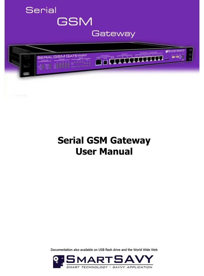
SmartSavy Serial GSM Gateway User manual

Serial GSM Gateway
Software Configuration Guide
Documentation also available on USB flash drive and the World Wide Web

Serial GSM Gateway Software Configuration Guide
Copyright © 2009-2010 Smartsavy Limited. All rights reserved.
2
Serial GSM Gateway
Software Configuration Guide
Head Office
SmartSAVY Limited
17 Tutchen Avenue
Raglan, Waikato 3225
New Zealand
Support: support@smartsavy.com
Website: www.smartsavy.com
New Zealand
Phone: +64 (0) 7 974 9029
Facsimile: +64 (0) 2 889 1205
South Africa
Phone: +27 (0) 87 750 9849
Australia
Phone: +61 (0) 86 222 5149
United Kingdom
Phone: +44 (0) 207 043 1395
Other Countries
Phone: +64 (0) 7 974 9029

Serial GSM Gateway Software Configuration Guide
Copyright © 2009-2010 Smartsavy Limited. All rights reserved.
3
THE SPECIFICATIONS AND INFORMATION REGARDING THE PRODUCTS IN THIS MANUAL ARE SUBJECT TO
CHANGE WITHOUT NOTICE. ALL STATEMENTS, INFORMATION, AND RECOMMENDATIONS IN THIS MANUAL ARE
BELIEVED TO BE ACCURATE BUT ARE PRESENTED WITHOUT WARRANTY OF ANY KIND, EXPRESS OR IMPLIED.
USERS MUST TAKE FULL RESPONSIBILITY FOR THEIR APPLICATION OF ANY PRODUCTS.
THE SOFTWARE LICENSE AND LIMITED WARRANTY FOR THE ACCOMPANYING PRODUCT ARE SET FORTH IN THE
INFORMATION DOCUMENT THAT SHIPPED WITH THE PRODUCT AND ARE INCORPORATED HEREIN BY THIS
REFERENCE. IF YOU ARE UNABLE TO LOCATE THE SOFTWARE LICENSE OR LIMITED WARRANTY, CONTACT
SMARTSAVY LIMITED or a SMARTSAVY LIMITED REPRESENTATIVE FOR A COPY.
This equipment generates, uses, and can radiate radio-frequency energy and, if not installed and used in
accordance with the instruction manual, may cause harmful interference to radio communications. Operation of
this equipment in a residential area is likely to cause harmful interference, in which case users will be required to
correct the interference at their own expense.
You can determine whether your equipment is causing interference by turning it off. If the interference stops, it
was probably caused by the Smartsavy Limited equipment or one of its peripheral devices. If the equipment causes
interference to radio or television reception, try to correct the interference by using one or more of the following
measures:
•Turn the television or radio antenna until the interference stops.
•Move the equipment to one side or the other of the television or radio.
•Move the equipment farther away from the television or radio.
•Plug the equipment into an outlet that is on a different circuit from the television or radio. (That is, make
certain the equipment and the television or radio are on circuits controlled by different circuit breakers or
fuses.)
NOTWITHSTANDING ANY OTHER WARRANTY HEREIN, ALL DOCUMENT FILES AND SOFTWARE OF THESE
SUPPLIERS ARE PROVIDED ―AS IS‖ WITH ALL FAULTS. SMARTSAVY LIMITED AND THE ABOVE-NAMED SUPPLIERS
DISCLAIM ALL WARRANTIES, EXPRESSED OR IMPLIED, INCLUDING, WITHOUT LIMITATION, THOSE OF
MERCHANTABILITY, FITNESS FOR A PARTICULAR PURPOSE AND NONINFRINGEMENT OR ARISING FROM A
COURSE OF DEALING, USAGE, OR TRADE PRACTICE.
IN NO EVENT SHALL SMARTSAVY LIMITED OR ITS SUPPLIERS BE LIABLE FOR ANY INDIRECT, SPECIAL,
CONSEQUENTIAL, OR INCIDENTAL DAMAGES, INCLUDING, WITHOUT LIMITATION, LOST PROFITS OR LOSS OR
DAMAGE TO DATA ARISING OUT OF THE USE OR INABILITY TO USE THIS MANUAL, EVEN IF SMARTSAVY
LIMITED OR ITS SUPPLIERS HAVE BEEN ADVISED OF THE POSSIBILITY OF SUCH DAMAGES.
All other trademarks mentioned in this document or website are the property of their respective owners. The use
of the word partner does not imply a partnership relationship between Smartsavy Limited and any other company.

Serial GSM Gateway Software Configuration Guide
Copyright © 2009-2010 Smartsavy Limited. All rights reserved.
4
CHAPTER 1111111
Document History
Date
Version
Author
Notes
19/01/2010
1.0
Smartsavy - Jason Brand
First Release
13/03/2010
1.1
Smartsavy - Jason Brand
Updated LAN console menu

Serial GSM Gateway Software Configuration Guide
Copyright © 2009-2010 Smartsavy Limited. All rights reserved.
5
CONTENTS111111
Document History ...................................................................................................................................................................................4
About This Guide ....................................................................................................................................................................................8
Audience ...........................................................................................................................................................................................8
Configuration Guide Overview.............................................................................................................................................................9
Installation Guide Conventions ..........................................................................................................................................................10
Overview of the Serial GSM Gateway .....................................................................................................................................................11
Serial GSM Gateway Features and User Configurable Settings.............................................................................................................12
Introduction to Configuring the Serial GSM Gateway ...............................................................................................................................15
Description of Consoles ....................................................................................................................................................................16
Establish a connection to the LAN Console (PRO model only)..............................................................................................................18
Establish a connection to the USB Console (All models) .....................................................................................................................21
Establish a connection to the SER Console (All models) .....................................................................................................................24
Establish a connection to the GPRS Console.......................................................................................................................................27
Configuring the Serial GSM Gateway ......................................................................................................................................................31
Logging into the Serial GSM Gateway ................................................................................................................................................32
The Main menu................................................................................................................................................................................33
User configurable settings to configure first .......................................................................................................................................34
The Settings menu ...........................................................................................................................................................................36
The Security menu ......................................................................................................................................................................38
The General Purpose Inputs menu................................................................................................................................................39
The General Purpose Outputs menu .............................................................................................................................................41
The GSM Prepaid menu................................................................................................................................................................42
The Setup external serial devices ports menu................................................................................................................................44
The Setup GPRS and DDNS menu.................................................................................................................................................46
The Setup device general alerts menu ..........................................................................................................................................50
The Setup device general timers menu .........................................................................................................................................52
The Setup LAN console menu (PRO model only)............................................................................................................................54
The Update firmware option.........................................................................................................................................................56
The Reset user settings to factory defaults option .........................................................................................................................57
Troubleshooting....................................................................................................................................................................................58
Problem Solving ...............................................................................................................................................................................59
Troubleshooting Console‘s and External Serial Devices...................................................................................................................60
Troubleshooting GPRS and SMS....................................................................................................................................................61
Obtaining Documentation......................................................................................................................................................................62
www.smartsavy.com ........................................................................................................................................................................62
Ordering Documentation USB Flash Drive ..........................................................................................................................................62
Documentation Feedback .................................................................................................................................................................62
Obtaining Technical Assistance ..............................................................................................................................................................63
Smartsavy Technical Support Website ...............................................................................................................................................63
Submitting a Service Request............................................................................................................................................................64
Definitions of Support Request Severity .............................................................................................................................................64
FIGURES111111

Serial GSM Gateway Software Configuration Guide
Copyright © 2009-2010 Smartsavy Limited. All rights reserved.
6
Figure 1-1 Serial GSM Gateway Front (Serial GSM Gateway PRO Model Shown) .............................................. 11
Figure 1-2 Serial GSM Gateway Professional, Logon Screen (PRO model) ....................................................... 12
Figure 1-3 Serial GSM Gateway Standard, Logon Screen (STD model)............................................................ 13
Figure 2-1 ‖PuTTY Configuration‖ screen for LAN console.............................................................................. 19
Figure 2-2 ‖PuTTY Configuration‖ LAN console session configuration ............................................................. 19
Figure 2-3 ‖PuTTY‖ LAN console session established ..................................................................................... 20
Figure 2-4 ‖PuTTY Configuration‖ screen for USB console ............................................................................. 21
Figure 2-5 ‖PuTTY Configuration‖ USB Console session configuration............................................................. 22
Figure 2-6 ‖PuTTY‖ Serial Configuration ....................................................................................................... 23
Figure 2-7 ‖PuTTY‖ USB console session established..................................................................................... 23
Figure 2-8 ‖PuTTY Configuration‖ screen for SER console.............................................................................. 24
Figure 2-9 ‖PuTTY Configuration‖ SER Console session configuration ............................................................. 25
Figure 2-10 ‖PuTTY‖ Serial Configuration ..................................................................................................... 26
Figure 2-11 ‖PuTTY‖ SER console session established ................................................................................... 26
Figure 2-12 Example of GPRS Ready SMS message from the Serial GSM Gateway .......................................... 27
Figure 2-13 ‖PuTTY Configuration‖ screen for GPRS console.......................................................................... 28
Figure 2-14 ‖PuTTY Configuration‖ GPRS console session configuration ......................................................... 28
Figure 2-15 ‖PuTTY‖ GPRS console session established ................................................................................. 29
Figure 2-16 Serial GSM Gateway Main Menu................................................................................................. 30
Figure 3-1 Logging into the Serial GSM Gateway........................................................................................... 32
Figure 3-2 Main menu tree structure ............................................................................................................ 33
Figure 3-3 Settings menu ............................................................................................................................ 36
Figure 3-4 Security menu ............................................................................................................................ 38
Figure 3-5 General purpose inputs menu ...................................................................................................... 39
Figure 3-6 General purpose outputs menu.................................................................................................... 41
Figure 3-7 GSM prepaid menu ..................................................................................................................... 42
Figure 3-8 Setup external serial devices ports menu...................................................................................... 44
Figure 3-9 Setup GRPS and DDNS menu ...................................................................................................... 47
Figure 3-10 Smartsavy Base64 encoder application ....................................................................................... 49
Figure 3-11 Setup device general alerts menu .............................................................................................. 50
Figure 3-12 Setup device general timers menu ............................................................................................. 52
Figure 3-13 Setup LAN console menu........................................................................................................... 54
Figure 3-14 Update firmware option - In Progress......................................................................................... 56
Figure 3-15 Reset user settings to factory defaults........................................................................................ 57

Serial GSM Gateway Software Configuration Guide
Copyright © 2009-2010 Smartsavy Limited. All rights reserved.
7
TABLES111111
Table 1 Serial GSM Gateway User Configurable Settings................................................................................ 13
Table 2 Settings menu options description.................................................................................................... 37
Table 3 Security menu options description.................................................................................................... 38
Table 4 General purpose inputs menu options description ............................................................................. 40
Table 5 General purpose inputs action description ........................................................................................ 40
Table 6 General purpose outputs menu options description ........................................................................... 41
Table 7 GSM prepaid menu options description............................................................................................. 43
Table 8 Setup external serial devices ports menu options description ............................................................. 45
Table 9 Setup GPRS and DDNS menu options description.............................................................................. 47
Table 10 Setup general device alerts menu options description...................................................................... 51
Table 11 Setup general device timers menu options description..................................................................... 53
Table 12 Setup LAN console options description ........................................................................................... 55

Serial GSM Gateway Software Configuration Guide
Copyright © 2009-2010 Smartsavy Limited. All rights reserved.
8
CHAPTER 1111111
About This Guide
This section discusses the audience, organization, and conventions of this Smartsavy Serial GSM Gateway
Software configuration guide.
Smartsavy documentation and additional literature are available in an embedded package, which ships inside
your product, and a USB memory stick package which is available on request. The Documentation USB
memory stick is updated monthly. Therefore, it might be more current than embedded package
documentation. To order additional copies of the documentation on USB memory stick, contact your local
sales representative, buy online at URL:
http://www.smartsavy.com/products/Serial-GSM-Gateway-Documentation-USB-memory-stick.html
or call Smartsavy customer support. The USB memory stick package is available as a single package.
You can also access Smartsavy documentation on the World Wide Web at http://www.smartsavy.com.
Audience
This guide is designed for the person configuring the Serial GSM Gateway family, who should be familiar with
networking protocols (such as IP), General Packet Radio Service (GPRS) configuration, Telnet and Terminal
emulation software, General GSM features such as Short Message Service (SMS).
Use this guide together with the
Serial GSM Gateway
Quick Start Guide
,
Serial GSM Gateway Hardware
Installation Guide
, and the
Serial GSM Gateway User Manual
that came with your Serial GSM Gateway.

Serial GSM Gateway Software Configuration Guide
Copyright © 2009-2010 Smartsavy Limited. All rights reserved.
9
Configuration Guide Overview
This guide contains the following chapters and appendices:
•About This Guide—Provides an overview of and describes conventions of this document.
•Overview of the Serial GSM Gateway—Provides an overview of the Serial GSM Gateway models,
including identifying the model, and product features.
•Introduction to Configuring the Serial GSM Gateway—Describes how to connect and configure the
Serial GSM Gateway from the LAN (PRO model only), USB and SER console ports and describes Serial GSM
Gateway Menu and how to navigate.
•Configuring the Serial GSM Gateway—Describes how to configure all of the Serial GSM Gateway user
configurable features.
•
Troubleshooting—Describes how to isolate problems you might encounter with the Serial GSM
Gateway or to rule out the Serial GSM Gateway as the source of the problem.
•
Obtaining Documenation—Describes how to obtain documenation
•
Obtaining Technical Assisatnce—Describes how to obtain technical assistance

Serial GSM Gateway Software Configuration Guide
Copyright © 2009-2010 Smartsavy Limited. All rights reserved.
10
Installation Guide Conventions
This guide uses the following conventions:
•Boldface font is used for commands and keywords.
•
Italic
is used for command input that is supplied by you.
•Screen font is used for examples of information that is displayed on the screen.
•Boldface screen font is used for examples of information that you enter.
•Square brackets contain keywords or arguments that are optional or default responses to system
prompts:
[ x ]
•Braces contain a choice of keywords (represented by x below) that are separated by vertical bars:
{ x | x | x }
•Angled brackets contain characters that are customer chosen or represent a character, such as space:
<space>
•The key labeled Control is represented by ^ or Ctrl-D. For example, when you read
^D
or
Ctrl-D
,
you should hold down the Control key while you press the D key.
Note Means reader take note. Notes contain helpful suggestions or references to material not
contained in this guide.
Caution Means reader be careful. In this situation, you might do something that could result in
equipment damage or loss of data.

Serial GSM Gateway Software Configuration Guide
Copyright © 2009-2010 Smartsavy Limited. All rights reserved.
11
CHAPTER 1111111
1. Overview of the Serial GSM Gateway
Smartsavy‘s Serial GSM Gateway‘s are a family of rack mountable devices that provide for local and remote
serial device access, and building management in a single appliance.
The Serial GSM Gateway family creates a 1 to 4 serial switch which can support up to four serial devices
such as routers, switches, PABX‘s, radio‘s etc. All external serial devices are then accessible via four different
console access methods. The access methods are Local Serial connection, Local USB connection, Remote
GPRS connection and Remote LAN connection (Pro Model Only) and each method displays an easy to use
software menu. A good analogy would be a KVM device, except in this case only serial data is switched. The
Serial GSM Gateway is unique in that it extends the serial console port to the end user over four different
communication mediums, which are: Local Serial Port, and Local USB Port using a terminal or a PC with
terminal emulation software, Remote Internet over GPRS Port, and Remote LAN Port (PRO version only) using
a PC or Smartphone with telnet virtual terminal connection software.
Smartsavy‘s Serial GSM Gateway family also creates a building management and telemetry solution. Built-in
General Purpose Input and Output (GPIO‘s) ports are provided, to connect external devices to the Serial
GSM Gateway, these sense and react to the outside environment. Connection of external devices such as
movement sensors, sirens, generators, lights, door locks, flood sensors etc... Provide for building automation
and management with comprehensive alerting and management available on the local and remote consoles
as well as SMS.
Location awareness is available via GPS technology. Site location co-ordinates can be requested via a simple
SMS message to the Serial GSM Gateway and a response SMS with GPS navigator compatible co-ordinates.
This feature is especially helpful to large organizations with many remote sites.
This chapter contains the following sections:
•Serial GSM Gateway Features and User configurable Settings
Figure 1-1 Serial GSM Gateway Front (Serial GSM Gateway PRO Model Shown)

Serial GSM Gateway Software Configuration Guide
Copyright © 2009-2010 Smartsavy Limited. All rights reserved.
12
Serial GSM Gateway Features and User Configurable Settings
Note The Serial GSM Gateway family is available as either a Standard or a Professional model. Serial GSM
Gateway model names with a STD suffix are standard Serial GSM Gateway‘s. Serial GSM Gateway‘s
with a PRO suffix are Professional Serial GSM Gateway‘s. In this document, model names will only be
used when a feature is only available on the respective model referenced. If the model name is not
used, both models, STD and PRO, are to be treated as a single model and share the same feature.
The model of the Serial GSM Gateway can be identified by viewing the device information displayed at
the top of the logon, main menu screens and from the ―Show MAC Address‖option located in the
―Device Functions‖menu.
The Professional model will have the letters ―PRO‖as a suffix on the model description, and the MAC
Address will have a valid MAC address. See Figure 1-2 for example.
The Standard model will have the letters ―STD‖as a suffix on the model description, and the MAC
Address will have the letters ―N/A‖. See Figure 1-3 for example.
Figure 1-2 Serial GSM Gateway Professional, Logon Screen (PRO model)

Serial GSM Gateway Software Configuration Guide
Copyright © 2009-2010 Smartsavy Limited. All rights reserved.
13
Figure 1-3 Serial GSM Gateway Standard, Logon Screen (STD model)
Listed below are the Software features list Table 1 to compare differences between the STD and PRO
models.
Table 1 Serial GSM Gateway User Configurable Settings
User Configurable Settings
STD
Model
PRO
Model
Configurable User Settings
√
√
GSM PIN code
√
√
GSM PUK code
√
√
Enable/Disable PIN code
√
√
Device Name
√
√
Device Date/Time
√
√
General Purpose Inputs Description
√
√
General Purpose Inputs SMS alerts mobile number
√
√
General Purpose Inputs SMS alerts Enable/Disable
√
√
General Purpose Inputs Activate General Purpose Output
√
√
General Purpose Inputs Activate General Purpose Output ON Internal
√
√
General Purpose Inputs Activate General Purpose Output Enable/Disable
√
√
General Purpose Outputs Description
√
√
GSM Prepaid Enable/Disable
√
√
GSM Prepaid USSD number for Balance checks
√
√
GSM Prepaid USSD number for Balance topups
√
√
GSM Prepaid Low Balance Alert Enable or Disable
√
√
GSM Prepaid Low Balance SMS alert mobile number
√
√
External Serial Devices Descriptions
√
√
Global Serial Baud rate
√
√
GPRS APN
√
√
GPRS Username
√
√
GPRS Password
√
√
GPRS Server and Client TCP port
√
√

Serial GSM Gateway Software Configuration Guide
Copyright © 2009-2010 Smartsavy Limited. All rights reserved.
14
GPRS Server wait for connection timeout
√
√
DDNS Enable or Disable
√
√
DDNS username and password
√
√
DDNS host name
√
√
Temperature High Alert threshold
√
√
Temperature High Alert SMS mobile number
√
√
Temperature High Enable or Disable alerting
√
√
Battery Low Alert threshold
√
√
Battery Low Alert SMS mobile number
√
√
Battery Low Enable or Disable alerting
√
√
Mains Power Failure Alert SMS mobile number
√
√
Mains Power Failure Enable or Disable alerting
√
√
SMS message check internal timer
√
√
Prepaid Balance check internal timer
√
√
GPS Location check internal timer
√
√
Temperature check internal timer
√
√
Battery Level check internal timer
√
√
LAN Server TCP Port
√
LAN IP address configuration methods - Static, DHCP and PPPoE
√
LAN IP Address
√
LAN Subnet Mask
√
LAN Default Gateway
√

Serial GSM Gateway Software Configuration Guide
Copyright © 2009-2010 Smartsavy Limited. All rights reserved.
15
CHAPTER 2111111
2. Introduction to Configuring the Serial GSM Gateway
This chapter contains connecting and configuration procedures for the Smartsavy Serial GSM Gateway
family and includes the following sections:
•Description of Consoles
•Establish a connection to the LAN console (PRO model only)
•Establish a connection to the USB console
•Establish a connection to the SER console
•Establish a connection to the GPRS console
•The Serial GSM Gateway Menu and Navigation

Serial GSM Gateway Software Configuration Guide
Copyright © 2009-2010 Smartsavy Limited. All rights reserved.
16
Description of Consoles
The Serial GSM Gateway has four options to connect to its Menu. These options are:
Local Access - USB or SER RS-232
Remote Access –LAN or GPRS
Note The USB and SER options enforce the use of Hardware Flow Control (RTS/CTS). If Hardware
Flow Control is not used in your session connection, the Serial GSM Gateway will not respond with
the logon prompt.
Note The USB, SER and LAN options all share an internal RS-232 communications bus. You are able to
access the Serial GSM Gateway menu using all three options one at a time or simultaneously.
The GPRS option will disable the USB, SER and LAN options when in use.
Note Most Terminal Emulation and Virtual Terminal Emulation applications can be used. Smartsavy
recommends the use of ―PuTTY‖. ―PuTTY‖is available either by download from the Internet or as an
installation package located in the embedded CD Rom of the Serial GSM Gateway.
The Serial GSM Gateway embedded CD Rom hosts a number of installation packages for
―PuTTY‖ that support ―PuTTY‖versions for PC, Symbian® and Microsoft® Windows Mobile™. Refer
to the
Serial GSM Gateway Hardware Installation Guide
to access the installation packages.
Local Access
USB Console
- The USB console is a USB to RS-232 Bridge. On installing the provided drivers as
described in the
Serial GSM Gateway Hardware Configuration Guide
, a COM Port
names ―Smartsavy Serial Port‖ will be available to your Terminal Emulation
Application.
SER RS-232 Console
- The SER console is a RS-232 to RS-232 bridge. No drivers are required,
but to use this option you require a functional COM Port to be available to
your Terminal Emulation Application.
Terminal Emulation application Settings
- When establishing a connection from your Terminal
Emulation application to either the USB or SER consoles, The Serial GSM Gateway
factory default COM Port settings are:
9600 Baud
8 data bits
No parity generated or checked
1 stop bit
Hardware flow control (RTS/CTS)

Serial GSM Gateway Software Configuration Guide
Copyright © 2009-2010 Smartsavy Limited. All rights reserved.
17
Remote Access
LAN Console (PRO Model ONLY) - The LAN console is an Ethernet to RS-232 Bridge. No Drivers
are required, but to use this option you require your PC to be connected and
functional on your LAN and the Serial GSM Gateway LAN port is able to be
contacted from your PC. You will also require a Virtual Terminal Emulation
application (TELNET). The LAN console functions as a Terminal Server on your
network.
Virtual Terminal Emulation Application settings
- When establishing a connection
from your Virtual Terminal Emulation application to the LAN console, The Serial
GSM Gateway factory default settings are:
IP Address: 192.168.1.1
Mask: 255.255.255.0
Gateway: 0.0.0.0
TCP Port: 23
GPRS Console - The GPRS console is an Ethernet to RS-232 Bridge. No Drivers are required, but to
use this option you require a GSM SIM card that is functional and able to establish a
connection to your mobile network provider using GPRS services.
Internet access from your PC and a Virtual Terminal Emulation application is
required.
The GPRS console works in two modes: Server and Client.
Server Mode -
Server mode allows you to specify the IP address of the Serial GSM
Gateway in your Virtual Terminal Emulation application and connect to the Serial
GSM Gateway menu much the same as the LAN console. The Serial GSM Gateway
will only connect and listen on the Internet for an inbound connection when
instructed by the customer either by SMS or selecting the Server option from the
Serial GSM Gateway menu when accessed from a local console. The Server
functions as a Terminal Server on the Internet.
Client Mode
–Client mode allows the Serial GSM Gateway to establish the
connection to your Virtual Terminal Emulation application. This mode will require
your PC to have a valid Internet IP address. Your Virtual Terminal Emulation
application becomes the Terminal Server on the Internet. The Serial GSM Gateway
will only establish the connection once the customer has instructed the Serial GSM
Gateway to do so. A Valid IP address for the Host PC is required to be given to the
Serial GSM Gateway either by SMS or the Client option from the Serial GSM
Gateway menu when accessed from a local console.
Virtual Terminal Emulation Application settings
- When establishing a connection
from your Virtual Terminal Emulation application to the GPRS console, The Serial
GSM Gateway factory default settings are:
IP Address: Provided by the mobile network operator (DHCP) and supplied
to the customer either in SMS message or on screen if using
local Serial GSM Gateway console
TCP Port: 23
Note GPRS Server mode may require your mobile operator to unblock inbound TCP
connections to the Serial GSM Gateway. Consult your mobile network operator.
GPRS Client mode may require reconfiguration of your network. Configuration
changes such as NAT and firewall may be required. Consult your local network
administrator.

Serial GSM Gateway Software Configuration Guide
Copyright © 2009-2010 Smartsavy Limited. All rights reserved.
18
Establish a connection to the LAN Console (PRO model only)
Follow these steps to establish a connection to the Serial GSM Gateway LAN console:
Note ―PuTTY‖ application is used for this section.
Note Factory default settings for the Serial GSM Gateway LAN console are used for this section.
IP Address: 192.168.1.1
Mask: 255.255.255.0
Gateway: 0.0.0.0
TCP Port: 23
Note Smartsavy provides a utility called “LAN Finder” that is located on the CD Rom menu. The utility
will search your LAN for all Smartsavy devices and return their current network configuration. The
utility uses a broadcast message to 255.255.255.255 which may be affected by your local network
configuration. See your local network administrator to check if broadcasts are configured on your
network.
Step 1 Open ―PuTTY‖ application. You will be presented with the ―PuTTY Configuration‖screen.
(Figure 2-1)

Serial GSM Gateway Software Configuration Guide
Copyright © 2009-2010 Smartsavy Limited. All rights reserved.
19
Figure 2-1 ”PuTTY Configuration” screen for LAN console
Step 2 Select the ‗Telnet‘ option and enter the IP Address ‗192.168.1.1‘ in the ‗Host Name‘ box and ‗23‘ in
the ‗Port‖ box. Click the ‗Open‘ button to establish the session with the Serial GSM Gateway
(Figure 2-2)
Figure 2-2 ”PuTTY Configuration” LAN console session configuration

Serial GSM Gateway Software Configuration Guide
Copyright © 2009-2010 Smartsavy Limited. All rights reserved.
20
Step 3 Once a successful connection has been established with the Serial GSM Gateway, The Logon menu
will be displayed in the session window. (Figure 2-3)
Figure 2-3 ”PuTTY” LAN console session established
Other manuals for Serial GSM Gateway
1
Table of contents
Other SmartSavy Gateway manuals
Popular Gateway manuals by other brands

Secure Computing
Secure Computing SG300 user manual
FingerTec
FingerTec AC100C quick start guide
Arris
Arris SURFboard SBG6700-AC user guide

ZyXEL Communications
ZyXEL Communications ZyXEL Prestige 310 user guide
Amatis
Amatis Sigma Luminous Border Router SL-AMBR user manual

King gates
King gates Star MM 224 instruction manual
