manuals.online logo
Brands
  1. Home
  2. •
  3. Brands
  4. •
  5. SMC Networks
  6. •
  7. Cables And Connectors
  8. •
  9. SMC Networks TRTU Series User manual

SMC Networks TRTU Series User manual

Improved spatter resistanceImproved spatter resistance
∗In SMC conditions
Spatter resistance is improved
by installing an aluminum layer
between the outer layer and
inner tube.
Spatter resistance is improved
by installing an aluminum layer
between the outer layer and
inner tube.
6-color variations
Black White Red Blue Yellow Green
Model — 20 m roll — 100 m reel
Model TRTU1208
12
8
1
TRTU1065
10
6.5
1
TRTU0805
8
5
1
TRTU0604
6
4
1
Inner tube O.D. (mm)
Inner tube I.D. (mm)
Outer layer thickness (mm)
Black (B)
White (W)
Red (R)
Blue (BU)
Yellow (Y)
Green (G)
Flame resistant polyolefin
(Equivalent to UL-94 standard V-0)
Aluminum laminated film
Polyurethane
FR Three-layer Polyurethane Tubing
Flame Resistant (Equivalent to UL-94 Standard V-0)
Three-
layer
design
Outer
layer
Middle
layer
Inner
tube
Spatter resistance is that of FR
double layer polyurethane tubing TRBU series.
Spatter resistance is that of FR
double layer polyurethane tubing TRBU series.
For general pneumatic and water
piping in environments exposed
to sparks from arc welding, etc.
Outer layer color
twicetwice
CAT.ES50-35A
Series TRTU
New
New
RoHS
Courtesy of Steven Engineering, Inc.-230 Ryan Way, South San Francisco, CA 94080-6370-Main Office: (650) 588-9200-Outside Local Area: (800) 258-9200-www.stevenengineering.com

2R
Middle layer
Aluminum laminated film
Outer layer
Flame resistant polyolefin
(Equivalent to UL-94 standard V-0)
Inner tube
Polyurethane
For general pneumatic and water
piping in environments exposed
to sparks from arc welding, etc.
Fixed end
Note 1) Applicable for general industrial water. Please consult with SMC if using for the other kind
of fluid. Also, the surge pressure must be under the maximum operating pressure.
If the surge pressure exceeds the maximum operating pressure, it will result in damage to
fittings and tubes.
Note 2) The minimum bending radius is the representative value measured as shown in the left
figure. Allow extra length when piping since the tube may be bent if used under the
minimum bending radius.
Note 3) The color of all inner tubes is black.
Model
Specifications
쎲— 20 m roll 쏔— 100 m reel
Model TRTU1208
12
8
1
TRTU1065
10
6.5
1
TRTU0805
8
5
1
TRTU0604
6
4
1
Inner tube O.D. (mm)
Inner tube I.D. (mm)
Outer layer thickness (mm)
Black (B)
White (W)
Red (R)
Blue (BU)
Yellow (Y)
Green (G)
Outer
layer
color
Fluid Note 1)
Burst pressure
Min. bending radius (mm) Note 2)
Ambient and fluid temperature
Material
Applicable fittings
Max. operating
pressure
At 20°C
At 40°C
At 60°C
Inner tube
Middle layer
Outer layer
Air, Water
0.8 MPa
0.65 MPa
0.5 MPa
Refer to the burst pressure characteristics curve.
−20 to +60°C Water: 0 to 40°C (No freezing)
Polyurethane
Aluminum laminated film
Polyolefin (Equivalent to UL-94 standard V-0)
50 60 70 80
FR one-touch fittings: Series KR-W2
Metal one-touch fittings: Series KQB2
How to Order
TRTU1065 B 20
Tubing model
TRTU0604
TRTU0805
TRTU1065
TRTU1208
Color
Symbol
B
W
R
BU
Y
G
Color
Black
White
Red
Blue
Yellow
Green
Length per roll
Symbol
20
100
Length
20 m roll
100 m reel
Bend the tube into the U-form at a
temperature of 20°C. Fix one end and
close loop gradually. Measure 2R when
the deformed ratio of the tube diameter at
bending reaches 5%.
How to measure the
minimum bending radius
Burst Pressure Characteristics
Curve and Operating Pressure
Note 3)
0.0
1.0
2.0
3.0
4.0
−20 0 20 40 60
Operating temperature (°C)
Pressure (MPa)
Max. operating pressure
Burst pressure
RoHS
Model Inner tube O.D. x I.D. (mm)
6 x 4
8 x 5
10 x 6.5
12 x 8
1
SeriesTRTU
Flame Resistant (Equivalent to UL-94 Standard V-0)
FR Three-layer Polyurethane Tubing
TRTU-A.qxd 10.7.22 5:21 PM Page 2
Courtesy of Steven Engineering, Inc.-230 Ryan Way, South San Francisco, CA 94080-6370-Main Office: (650) 588-9200-Outside Local Area: (800) 258-9200-www.stevenengineering.com
Pitch indication (Series KQB2): All installation lengths with the same pitch
Pitch indication (Series KR-W2): All installation lengths with the same pitch
Installation on the KR-W2 series
Step 1
Step 2
Pitch length for installation on a one-touch fitting is indicated on the outer layer of the TRTU tubing.
(There are two types of applicable fittings, so two types of pitch length for installation are available.)
Cut the tube according to this indication (Step 1) and strip off the outer layer (Step 2) using a special tool.
Strip off the aluminum laminated film to prevent the inner tube from being damaged (Step 3) and install it on the one-touch fitting.
Refer to the Operation Manual for details of installation on the one-touch fitting.
The Operation Manual can be downloaded from the SMC URL below.
http://www.smcworld.com/
Strip off the outer layer.
Step 3
Strip off the aluminum laminated film to prevent
the inner tube from being damaged.
Metal one-touch fittings
Series KQB2
Flame resistant
(equivalent to UL-94 standard V-0)
FR one-touch fittings
Series KR-W2
Identification of the pitch length
for installation
“ ”: Series KQB2
“ ”: Series KR-W2
Outer layer, aluminum laminated film
and inner tube are cut at the “ ” mark.
Use a special tool for stripping
off the outer layer.
Part no.: YS-100
∗Refer to the Operation Manual
for details of how to use the
special tool.
Special tool
Series TRTU
Flame Resistant (Equivalent to UL-94 Standard V-0)
FR Three-layer Polyurethane Tubing
Tube
2
Installation on One-touch Fittings
TRTU-A.qxd 10.7.22 5:21 PM Page 3
Courtesy of Steven Engineering, Inc.-230 Ryan Way, South San Francisco, CA 94080-6370-Main Office: (650) 588-9200-Outside Local Area: (800) 258-9200-www.stevenengineering.com
1. The compatibility of the product is the responsibility of the
person who designs the equipment or decides its
specifications.
Since the product specified here is used under various operating
conditions, its compatibility with specific equipment must be decided by
the person who designs the equipment or decides its specifications
based on necessary analysis and test results. The expected performance
and safety assurance of the equipment will be the responsibility of the
person who has determined its compatibility with the product. This person
should also continuously review all specifications of the product referring
to its latest catalog information, with a view to giving due consideration to
any possibility of equipment failure when configuring the equipment.
2. Only personnel with appropriate training should operate
machinery and equipment.
The product specified here may become unsafe if handled incorrectly.
The assembly, operation and maintenance of machines or equipment
including our products must be performed by an operator who is
appropriately trained and experienced.
3. Do not service or attempt to remove product and
machinery/equipment until safety is confirmed.
1. The inspection and maintenance of machinery/equipment should only
be performed after measures to prevent falling or runaway of the
driven objects have been confirmed.
2. When the product is to be removed, confirm that the safety measures
as mentioned above are implemented and the power from any
appropriate source is cut, and read and understand the specific
product precautions of all relevant products carefully.
3. Before machinery/equipment is restarted, take measures to prevent
unexpected operation and malfunction.
4. Contact SMC beforehand and take special consideration of
safety measures if the product is to be used in any of the
following conditions.
1. Conditions and environments outside of the given specifications, or use
outdoors or in a place exposed to direct sunlight.
2. Installation on equipment in conjunction with atomic energy, railways,
air navigation, space, shipping, vehicles, military, medical treatment,
combustion and recreation, or equipment in contact with food and
beverages, emergency stop circuits, clutch and brake circuits in press
applications, safety equipment or other applications unsuitable for the
standard specifications described in the product catalog.
3. An application which could have negative effects on people, property,
or animals requiring special safety analysis.
4. Use in an interlock circuit, which requires the provision of double
interlock for possible failure by using a mechanical protective function,
and periodical checks to confirm proper operation.
Warning
Limited warranty and Disclaimer/
Compliance Requirements
The product used is subject to the following “Limited warranty and
Disclaimer” and “Compliance Requirements”.
Read and accept them before using the product.
1. The product is provided for use in manufacturing industries.
The product herein described is basically provided for peaceful use in
manufacturing industries.
If considering using the product in other industries, consult SMC
beforehand and exchange specifications or a contract if necessary.
If anything is unclear, contact your nearest sales branch.
Caution
Limited warranty and Disclaimer
1. The warranty period of the product is 1 year in service or 1.5
years after the product is delivered.∗2)
Also, the product may have specified durability, running distance or
replacement parts. Please consult your nearest sales branch.
2.
For any failure or damage reported within the warranty period which is
clearly our responsibility, a replacement product or necessary parts will
be provided.
This limited warranty applies only to our product independently, and not
to any other damage incurred due to the failure of the product.
3.
Prior to using SMC products, please read and understand the warranty
terms and disclaimers noted in the specified catalog for the particular
products.
∗2) Vacuum pads are excluded from this 1 year warranty.
A vacuum pad is a consumable part, so it is warranted for a year after it is
delivered.
Also, even within the warranty period, the wear of a product due to the use of
the vacuum pad or failure due to the deterioration of rubber material are not
covered by the limited warranty.
Compliance Requirements
1.
The use of SMC products with production equipment for the manufac-
ture of weapons of mass destruction (WMD) or any other weapon is
strictly prohibited.
2.
The exports of SMC products or technology from one country to
another are governed by the relevant security laws and regulations of
the countries involved in the transaction. Prior to the shipment of a
SMC product to another country, assure that all local rules governing
that export are known and followed.
These safety instructions are intended to prevent hazardous situations and/or
equipment damage. These instructions indicate the level of potential hazard with
the labels of “Caution,” “Warning” or “Danger.”They are all important notes for
safety and must be followed in addition to International Standards (ISO/IEC)∗1),
and other safety regulations.
∗1) ISO 4414: Pneumatic fluid power – General rules relating to systems.
ISO 4413: Hydraulic fluid power – General rules relating to systems.
IEC 60204-1: Safety of machinery – Electrical equipment of machines.
(Part 1: General requirements)
ISO 10218-1: Manipulating industrial robots - Safety.
etc.
Caution indicates a hazard with a low level of risk
which, if not avoided, could result in minor or
moderate injury.
Warning indicates a hazard with a medium level of
risk which, if not avoided, could result in death or
serious injury.
Caution:
Warning
:
Danger : Danger indicates a hazard with a high level of risk
which, if not avoided, will result in death or serious
injury.
Safety Instructions
Akihabara UDX 15F,
4-14-1, Sotokanda, Chiyoda-ku, Tokyo 101-0021, JAPAN
Phone: 03-5207-8249 Fax: 03-5298-5362
URL http://www.smcworld.com
© 2010 SMC Corporation All Rights Reserved
Specifications are subject to change without prior notice
and any obligation on the part of the manufacturer.
1st printing OV printing OV 7150SZ Printed in Japan.D-DN
Safety Instructions Be sure to read “Handling Precautions for SMC Products” (M-E03-3) before using.
TRTU-A.qxd 10.7.22 5:21 PM Page 4
Courtesy of Steven Engineering, Inc.-230 Ryan Way, South San Francisco, CA 94080-6370-Main Office: (650) 588-9200-Outside Local Area: (800) 258-9200-www.stevenengineering.com

This manual suits for next models

4

Other SMC Networks Cables And Connectors manuals

SMC Networks KQG2-F Series User manual

SMC Networks

SMC Networks KQG2-F Series User manual

SMC Networks KQB2-F Series User manual

SMC Networks

SMC Networks KQB2-F Series User manual

SMC Networks KKA Series User manual

SMC Networks

SMC Networks KKA Series User manual

SMC Networks KQG2 Series User manual

SMC Networks

SMC Networks KQG2 Series User manual

SMC Networks DM Series User manual

SMC Networks

SMC Networks DM Series User manual

SMC Networks KQB2 Series User manual

SMC Networks

SMC Networks KQB2 Series User manual

SMC Networks LEC-W2-U User manual

SMC Networks

SMC Networks LEC-W2-U User manual

SMC Networks M Series User manual

SMC Networks

SMC Networks M Series User manual

SMC Networks SMC8511W-G User manual

SMC Networks

SMC Networks SMC8511W-G User manual

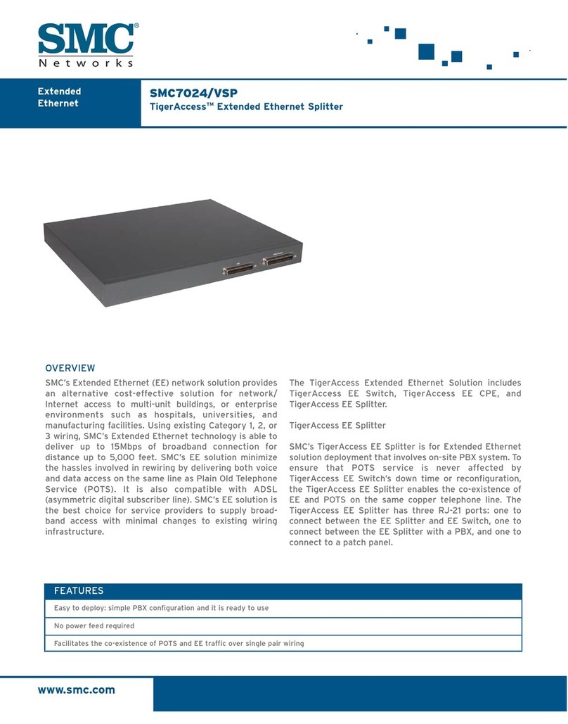
SMC Networks SMC7024 User manual

SMC Networks

SMC Networks SMC7024 User manual

SMC Networks Tiger Access Extended Ethernet Splitter... User manual

SMC Networks

SMC Networks Tiger Access Extended Ethernet Splitter... User manual

Popular Cables And Connectors manuals by other brands

Samson 506 SERIES Spare parts & operator's manual

Samson

Samson 506 SERIES Spare parts & operator's manual

Samsung SEA-C101 user manual

Samsung

Samsung SEA-C101 user manual

Hirose GT43 instruction manual

Hirose

Hirose GT43 instruction manual

Seneca SG-EQ4 installation manual

Seneca

Seneca SG-EQ4 installation manual

Redarc KIT24 quick start guide

Redarc

Redarc KIT24 quick start guide

Riyue CK3-105/VS instruction manual

Riyue

Riyue CK3-105/VS instruction manual

Renesas H8S/2218 Series user manual

Renesas

Renesas H8S/2218 Series user manual

Crestron FlipTop CBLR2 Series quick start

Crestron

Crestron FlipTop CBLR2 Series quick start

rocksoul HM-SP14SX12 operating instructions

rocksoul

rocksoul HM-SP14SX12 operating instructions

Exsys EX-1346IS manual

Exsys

Exsys EX-1346IS manual

GES GB MCS Series Assembly instructions

GES

GES GB MCS Series Assembly instructions

RIDGID SeeSnake CSx 66523 Operator's manual

RIDGID

RIDGID SeeSnake CSx 66523 Operator's manual

ClickTronic active HDMI manual

ClickTronic

ClickTronic active HDMI manual

Marmitek SPLIT312 user manual

Marmitek

Marmitek SPLIT312 user manual

Jabra GN1210 brochure

Jabra

Jabra GN1210 brochure

Blu Stream SC12SP user manual

Blu Stream

Blu Stream SC12SP user manual

Rocstor Y10C239-W1 user manual

Rocstor

Rocstor Y10C239-W1 user manual

NCR 7403-K112 Kit instructions

NCR

NCR 7403-K112 Kit instructions

manuals.online logo
manuals.online logoBrands
  • About & Mission
  • Contact us
  • Privacy Policy
  • Terms and Conditions

Copyright 2025 Manuals.Online. All Rights Reserved.