3IT
CONSIGLI E SUGGERIMENTI
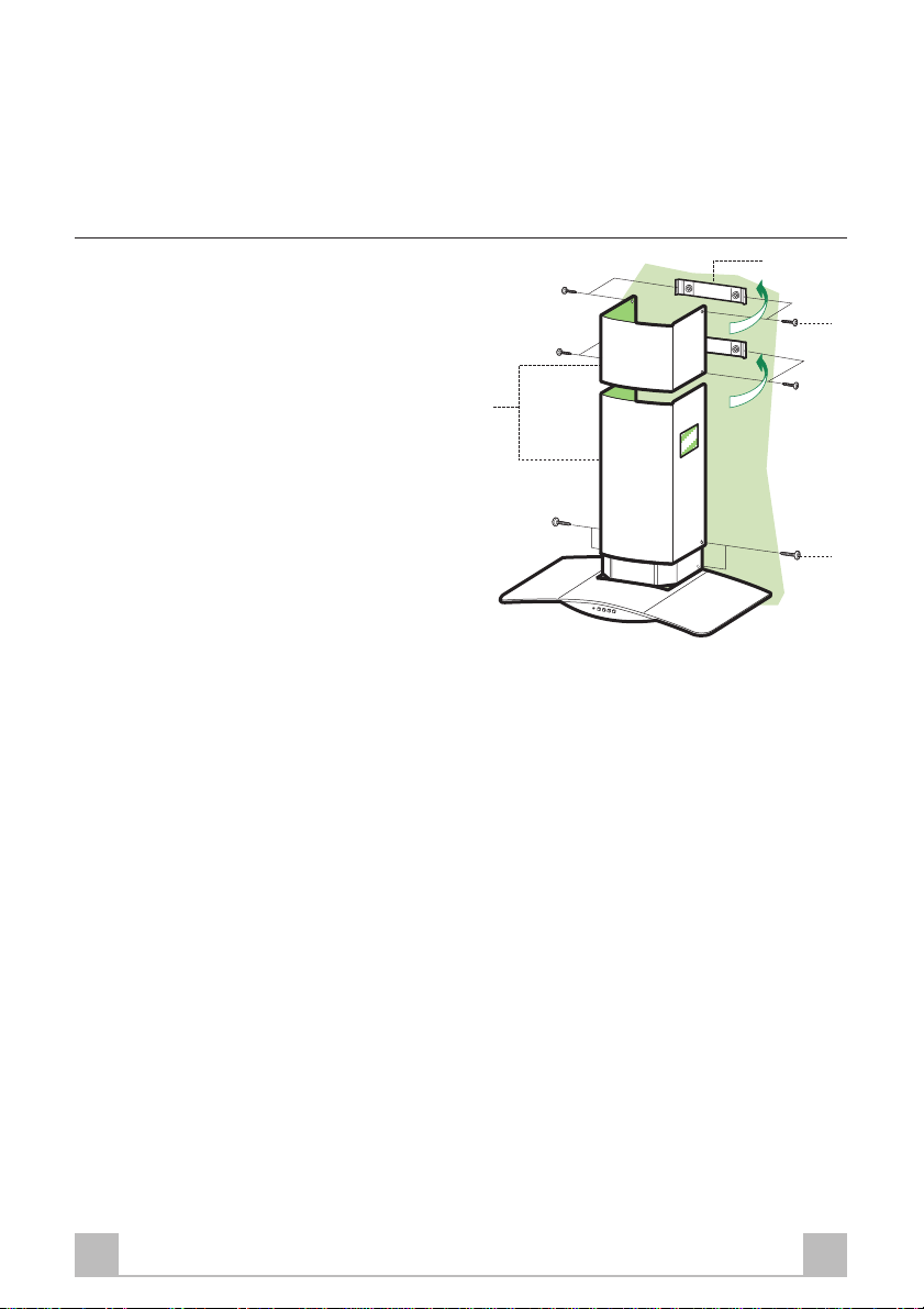
INSTALLAZIONE
• Il produttore declina qualsiasi responsabilità per danni dovuti ad
installazione non corretta o non conforme alle regole dell’arte.
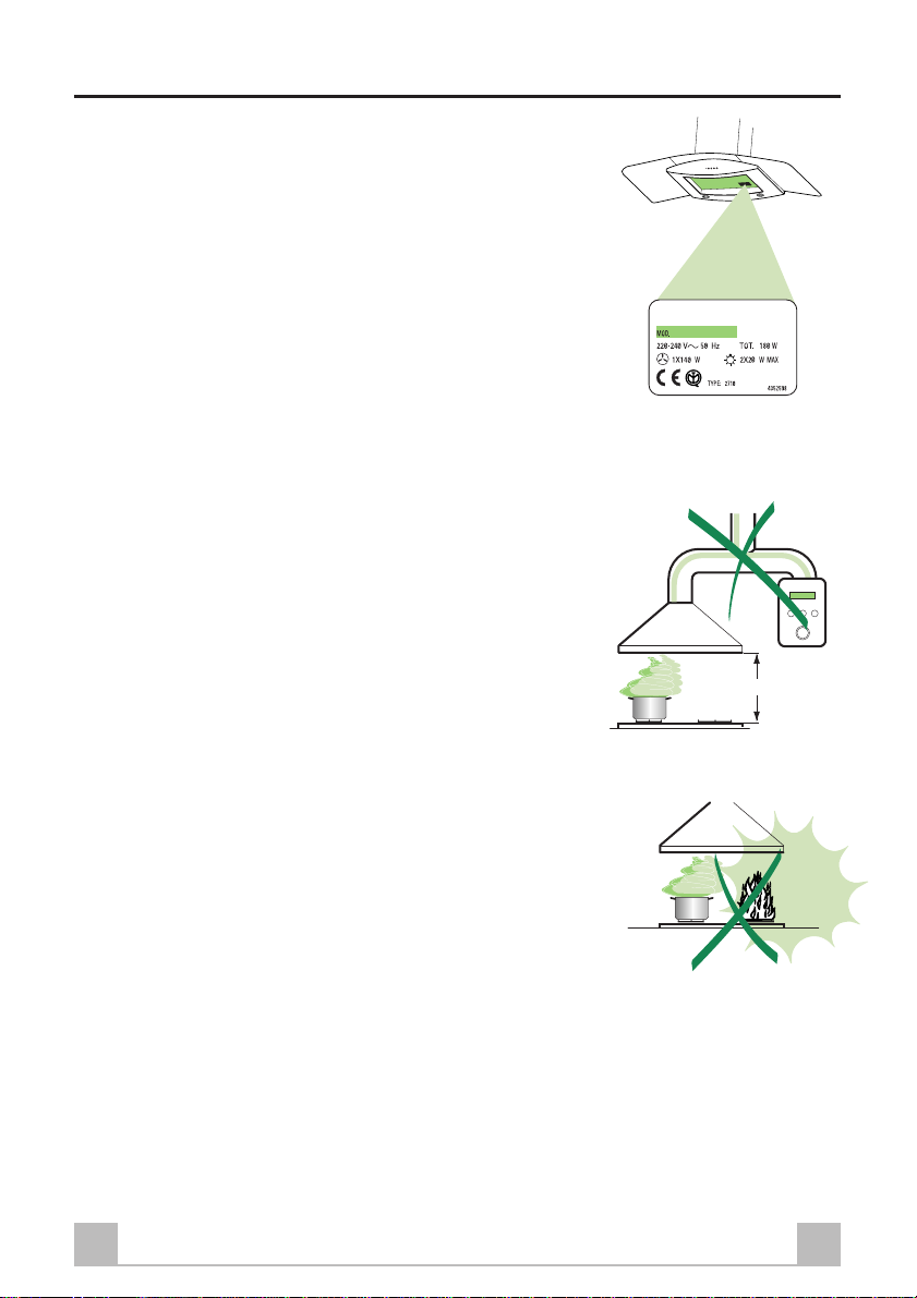
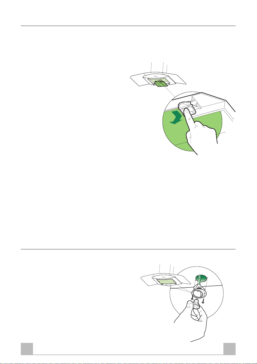
• La distanza minima di sicurezza tra il Piano di cottura e la Cappa
deve essere di 650 mm.
• Verificare che la tensione di rete corrisponda a quella riportata
nella targhetta posta all’interno della Cappa.
• Per Apparecchi in Classe Ia accertarsi che l’impianto elettrico do-
mestico garantisca un corretto scarico a terra.
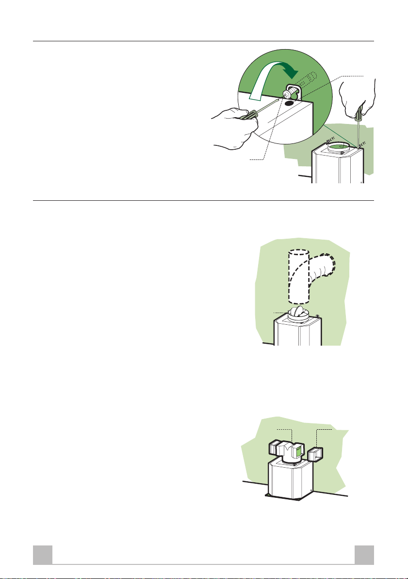
• Collegare la Cappa al Condotto di scarico con tubazione di dia-
metro pari o superiore a 120 mm. Il percorso della tubazione deve
essere il più breve possibile.
• Non collegare la Cappa a condotti di scarico dei fumi prodotti da
combustione (caldaie, caminetti, ecc.).
• Nel caso in cui nella stanza vengano utilizzati sia la Cappa che
Apparecchi non azionati da energia elettrica (ad esempio Appa-
recchi utilizzatori di gas), si deve provvedere ad una aerazione
sufficiente dell’ambiente. Se la cucina ne fosse sprovvista, prati-
care un’apertura che comunichi con l’esterno, per garantire il ri-
chiamo d’aria pulita.
USO
• La Cappa è stata progettata esclusivamente per Uso domestico,
per abbattere gli Odori della cucina.
• Non fare mai uso improprio della Cappa.
• Non lasciare fiamme libere a forte intensità sotto la Cappa in fun-
zione.
• Regolare sempre le fiamme in modo da evitare una evidente fuo-
riuscita laterale delle stesse rispetto al fondo delle pentole.
• Controllare le friggitrici durante l’Uso: l’olio surriscaldato po-
trebbe infiammarsi.
• La Cappa non deve essere utilizzata da bambini o persone non
abilitate all’Uso corretto.
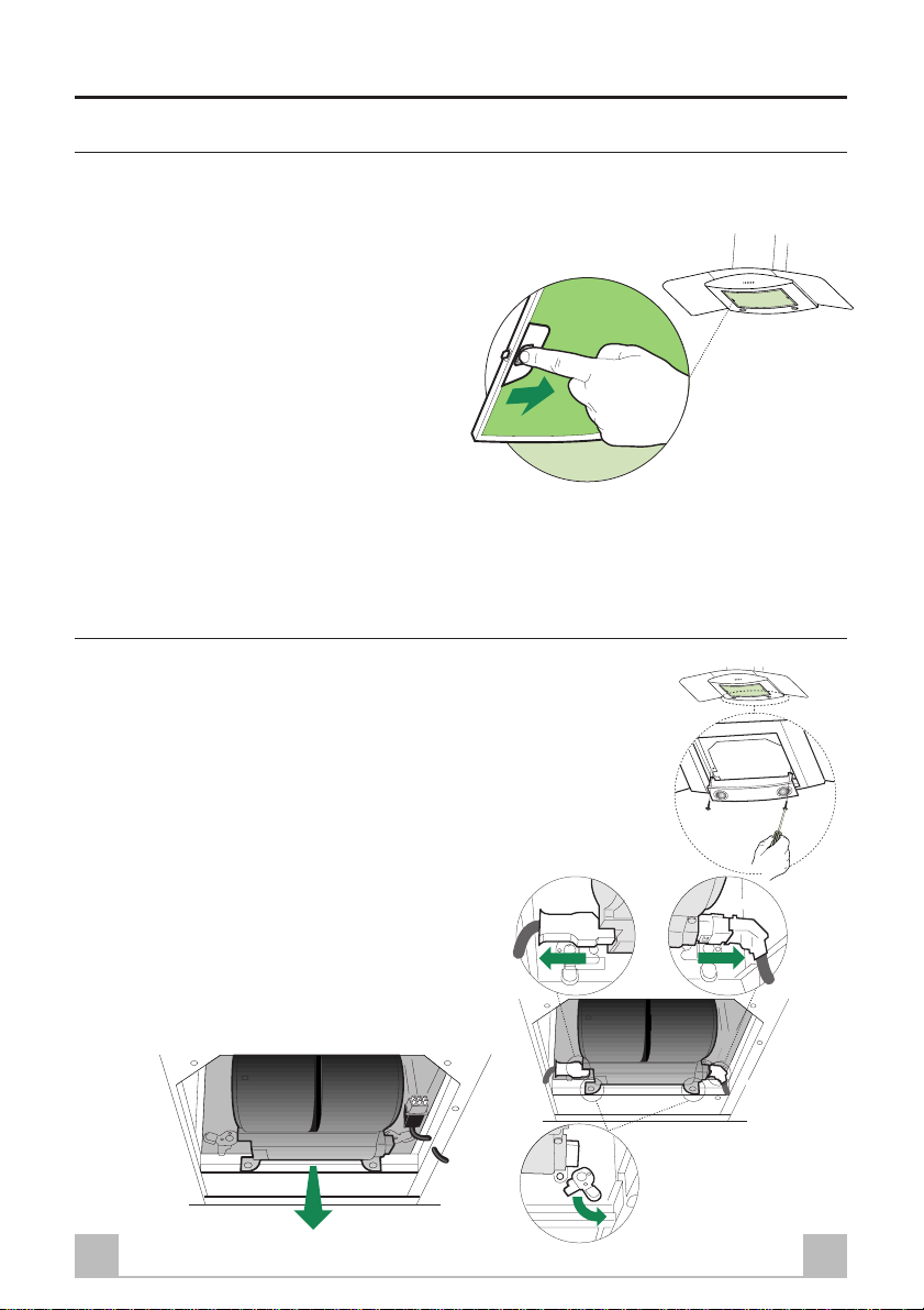
MANUTENZIONE
• Prima di procedere a qualsiasi operazione di Manutenzione,
scollegare la Cappa togliendo la spina elettrica o spegnendo l’in-
terruttore generale.
• Effettuare una scrupolosa e tempestiva Manutenzione dei Filtri
secondo gli intervalli consigliati.
• Per la pulizia delle superfici della Cappa è sufficiente utilizzare
un panno umido e detersivo liquido neutro.
650 mm min.