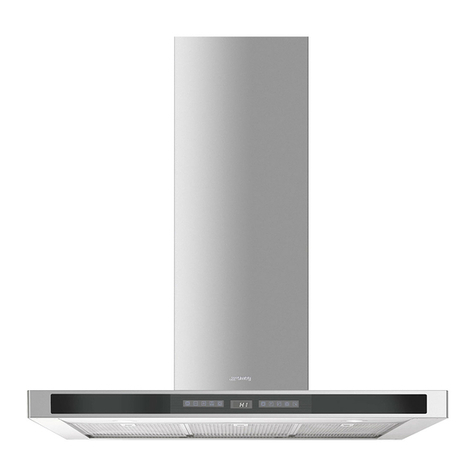
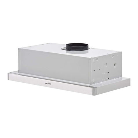
Smeg SHC965X User manual

Instruction ManualGB
SHC965X

2
GB
RECOMMENDATIONS AND SUGGESTIONS
INSTALLATION
• The manufacturer will not be held liable for any damages resulting from
incorrectorimproperin-stallation.
• Theminimumsafetydistancebetweenthecookertopandtheextractorhood
is650mm(somemodelscanbeinstalledatalowerheight,pleaserefertothe
paragraphsonworkingdimensionsandinstallation).
• Checkthatthemainsvoltagecorrespondstothatindicatedontheratingplate
xedtotheinsideofthehood.
• For Class I appliances, check that the domestic power supply guarantees
adequateearthing.
Connecttheextractortotheexhaustuethroughapipeofminimumdiameter
120mm.Therouteoftheuemustbeasshortaspossible.
• Donotconnecttheextractorhoodtoexhaustductscarryingcombustionfumes
(boilers,replaces,etc.).
• Iftheextractorisusedinconjunctionwithnon-electricalappliances(e.g.gas
burningappliances),asufcientdegreeofaerationmustbeguaranteedinthe
roominordertopreventthebackowofexhaustgas.Thekitchenmusthave
anopeningcommunicatingdirectlywiththeopenairinordertoguaranteethe
entryofcleanair.Whenthecookerhoodisusedinconjunctionwithappliances
suppliedwithenergyotherthanelectric,thenegativepressureintheroommust
notexceed0,04mbartopreventfumesbeingdrawnbackintotheroombythe
cookerhood.
• Intheeventofdamagetothepowercable,itmustbereplacedbythemanu-
facturerorbythetechnicalservicedepartment,inordertopreventanyrisks.
“WARNING:Failuretoinstallthescrewsorxingdeviceinaccordancewith
theseinstructionsmayresultinelectricalhazards.”
USE
• Theextractorhoodhasbeendesignedexclusivelyfordomesticusetoeliminate
kitchensmells.
• Neverusethehoodforpurposesotherthanforwhichithasbeendesigned.
• Neverleavehighnakedamesunderthehoodwhenitisinoperation.
• Adjusttheameintensitytodirectitontothebottomofthepanonly,making
surethatitdoesnotengulfthesides.
• Deepfatfryersmustbecontinuouslymonitoredduringuse:overheatedoilcan
burstintoames.
• Donotambèundertherangehood;riskofre
• Thisapplianceisnotintendedforusebypersons(includingchildren)with
reducedphysical,sen-soryormentalcapabilities,orlackofexperienceand
knowledge,unlesstheyhavebeengivensu-pervisionorinstructionconcerning
useoftheappliancebyapersonresponsiblefortheirsafety.
• Childrenshouldbesupervisedtoensurethattheydonotplaywiththeappliance.
• “WARNING:Accessible parts may become hot when used with cooking
appliances.”.
MAINTENANCE
• Switchofforunplugtheappliancefromthemainssupplybeforecarryingout
anymaintenancework.
• Cleanand/orreplacetheFiltersafterthespeciedtimeperiod(Firehazard).
• Cleanthehoodusingadampclothandaneutralliquiddetergent.
Thesymbol ontheproductoronitspackagingindicatesthatthisproductmaynotbetreatedashouseholdwaste.Instead
itshallbehandedovertotheapplicablecollectionpointfortherecyclingofelectricalandelectronicequipment.Byensuring
thisproductisdisposedofcorrectly,youwillhelppreventpotentialnegativeconsequencesfortheenvironmentandhuman
health,whichcouldotherwisebecausedbyinappropriatewastehandlingofthisproduct.Formoredetailedinformationabout
recyclingofthisproduct,pleasecontactyourlocalcityofce,yourhouseholdwastedisposalserviceortheshopwhereyou
purchasedtheproduct.

3
GB
CHARACTERISTICS
Dimensions
Components
Ref. Q.ty Product Components
11 Hood Body, complete with: Controls, Light,
Blower, Filters
10 2 Dumper ø150
Ref. Q.ty Installation Components
Q.ty Documentation
1 Instruction Manual

4
GB
INSTALLATION
Drilling the Support surface and Fitting the Hood
TheHoodcanbetteddirectlytotheundersideoftheWallunits(min.650mmabovethecooker
top)withsnap-onsidesupports,whicharesetupforasupportpanelthicknessofbetween15mm
and30mm.
• Cutattedopeninginthebottomsurfaceofthe
wallunit,asshown.
• Remove the metal grease lters (see par. on
Maintenance).
•Removetheltersupport
• Disconnecttheltersupportbyturningtheinternal
handlesprovided.
• Insertthehooduntilthesidesupportssnapinto
place.
• Lockin position bytightening the screwsVf
fromunderneaththehood.
•Replacetheltersupport
• Screwtheltersupportusingthe2screws
provided.
• Replacethegreaseltersmakesurethatthe
handleisvisibleontheoutside.

5
GB
Connections
DUCTED VERSION AIR EXHAUST SYSTEM
Wheninstallingtheductedversion,connectthehoodtothechimneyusingarigid150mmduct.
• Installthedamper10ø150mm.
• Fix the duct in position using sufcient pipe
clamps(notsupplied).
RECIRCULATION VERSION AIR OUTLET
• Connect the hood canopy outlet
tothetoppartofthewallunitby
meansofarigidorexiblepipe
ofthesamediameter,thechoice
ofwhichisatthediscretionofthe
installer.
• Fixthepipeinpositionusingsuf-
cientpipeclamps(notsupplied).
•Ensurethattheactivatedcharcoal
ltershavebeeninserted.
ELECTRICAL CONNECTION
• Connectthehoodtothemainsthroughatwo-poleswitchhavingacontactgapofatleast3mm.
Version 03/08 - Page 6
PLAN YOUR DUCTWORK
To ensure that the blower performs to its highest
possible capacity, ductwork should be as short
and straight as possilbe.
The ductrun should not exceed 35 equivalent
feet if ducted using two separate duct runs of
the required minimum of 6" round duct or 55
equivalent feet if ducted with one single 10"
round duct (when using optional Duct Transi-
tion Kit). Calculate the length of the ductwork
by adding the equivalent feet in FIGURE 2 for
each piece of duct in the system An example
is given in FIGURE 3.
For best results, use no more than three 90°
elbows. Make sure that there is a minimum of
24" of straight duct between elbows if more
than one is used. Do not install two elbows
together. If you must elbow right away, do it
as far away from the hood's exhaust opening
as possible.
9 Feet Straight Duct
2 - 90˚ Elbows
Wall Cap
Total System
9.0 feet
10.0 feet
0.0 feet
19.0 feet
3.0 feet
5.0 feet
12.0 feet
0.0 feet
45˚ Elbow
90˚ Elbow
90˚ Flat Elbow
Wall Cap
FIGURE 1
RECIRCULATING INSTALLATIONS
IT IS HIGHLY RECOMMENDED THAT PROFESSIONAL STYLE COOKING ALWAYS BE VENTED TO THE OUTSIDE. For recirculating
installations (FIGURE 1), Charcoal Filters are necessary. Remove all three grease lters and set aside. Attach one charcoal lter to each end
of both blowers. Each charcoal lter attaches to the grid on the side of the blowers. Rotate the lter clockwise to install and counterclockwise
to remove (FIGURE 1A). Replace all three grease lters. Recirculating installations also require some duct work to divert the air out of the
top or face of the cabinet or custom hood. The duct work must not terminate inside the cabinet or custom hood.
cabinet
or
custom
hood
ceiling
duct
work
duct
work
ceiling
inca pro 38
cabinet
or
custom
hood
MAKE YOUR CUT-OUTS
1. Disconnect and move freestanding range from cabinet opening to provide easier access
to upper cabinet or custom hood. Put a thick, protective covering over cooktop, set-in range
or countertop to protect from damage or dirt.
2. Determine and clearly mark with a pencil the center line on the cabinet or custom hood
where the rangehood will be installed.
3. Determine and make all necessary cuts in the wall and/or ceiling for the ductwork. Install
the ductwork before the rangehood.
4. Determine the proper location for the Power Supply Cable. Use a 1 1/4" Drill Bit to make
this hole. Install the cable. Use caulking to seal around the hole. DO NOT turn on the
power until installation is complete.
5. Make the cut-out opening where the rangehood will be installed (FIGURE 4).
FIGURE 4
37"
14 5/8"
CUT-OUT
FIGURE 1A
inca pro 38
FIGURE 2
FIGURE 3

6
GB
USE
Control Panel
KEY FuNctIoNs
L Light Switchesthelightingsystemonandoff.
M Motor Switchestheextractormotoronandoff.
V Speed Setstheoperatingspeedoftheextractor:
1.Lowspeed,usedforacontinuousandsilentairchangeinthepresenceoflight
cookingvapour.
2.Medium speed, suitablefor mostoperating conditionsgiven the optimum
treatedairow/noiselevelratio.
3.Maximumspeed,usedforeliminatingthehighestcookingvapouremission,
includinglongperiods.

7
GB
MAINTENANCE
Grease lters
CLEANING METAL SELF- SUPPORTING GREASE FILTERS
• Theltersmustbecleanedeverytwomonthsof
operation,ormorefrequentlywithheavyusage,
andcanbewashedinadishwasher.
• Remove the lters one at a time, supporting
themwithonehandandturningthesafetyknobs
(pullandturn).
• Washthelters,takingcarenottobendthem.
Allowthemtodrybeforeretting.
• Replace them and x them using the safety
knobsprovided(pullandturn).
Odour lters (Recirculation version)
REPLACING THE ACTIVATED CHARCOAL FILTER
• Theseltersarenotwashableandcannotberegenerated,
andmustbereplacedapproximatelyeveryfourmonths
ofoperation,ormorefrequentlywithheavyusage.
• Removethegreaselters.
• Removethesaturatedactivatedcharcoalltersasshown
(A).
• Fitnewlters(B).
• Replacethegreaselters.
Lighting
LIGHT REPLACEMENT
• 35Whalogenlight.
• Removethe2screwsxingthelightcover.
• Remove the lamp by gripping the protruding
partandturningtotheleft.
• Replacewithanewlampwiththesamecha-
racteristics,makingsurethatyouinsertthetwo
pinsproperlyintotheirhousings.
• Replacethecoverandxitinpositionusing
thetwoscrewsremovedasabove

991.0266.699_01 - 120911
Table of contents
Other Smeg Ventilation Hood manuals

Smeg
Smeg KD91XE User manual

Smeg
Smeg T-9309-B User manual

Smeg
Smeg KSEG5XSA Technical manual

Smeg
Smeg Kitchen Hood KSE9600XL Setup guide

Smeg
Smeg KBT700XE Technical manual

Smeg
Smeg KSEG50 Technical manual

Smeg
Smeg KLT9L4X User manual

Smeg
Smeg KSMD910X Technical manual

Smeg
Smeg KR37XE User manual

Smeg
Smeg KSEIV950X Technical manual