SMERI PT-4S User manual
User Manual
PT - 4S Smart
Pressure Transmitter

- 1 -
I. Introduction
PT - 4S smart pressure transmitter is a versatile digital
instrument . Based on advanced, mature, reliable silicon sensor
technology, its design combines with advanced single-chip microcontroller
(SCM) and sensor digital conversion techniques.
Its core component SCM has powerful function and high-speed
computing capability, ensured high quality of the transmitter. The entire
design focuses on reliability, stability, high accuracy and intelligence.
PT - 4S also has powerful interface operation function; its digital LCD
can display pressure, pressure range percent, current and 0~100% analog
indicating. Buttons on display can easily fulfil the basic parameters setting
including zero migration, range changing, damping changing etc without
standard pressure source, greatly facilitate on-site debugging.
Signal conversion, signal acquisition and processing, and current output
controlling adopt dedicated integrated circuit (ASICS), so that the transmitter
is accurate, stable and reliable.
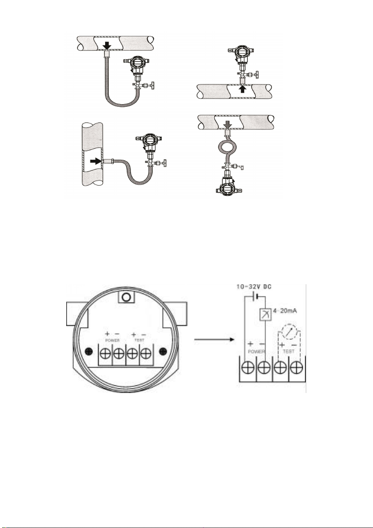
II. Installation
PT - 4S can be directly mounted on pressure pipe, or mounted by
bracket (mounting bracket needs to be ordered).
- 2 -
III. Electrical Connection
Unscrew cover of the wiring terminals to do wiring. Picture below shows
the typical wiring way; TEST terminal is used to connect any indicating
display or for testing. Supply power is with the signal line, without additional
wiring.
Attention:
Do not connect signal wire with power to the TEST terminals, which
will destroy the diode of test terminals.
If the diode is damaged accidentally, short-circuit TEST terminal can
resume working of transmitter, but the TEST terminals will not be able to
connect with Ammeter.

- 3 -
V. Calibration & Operation
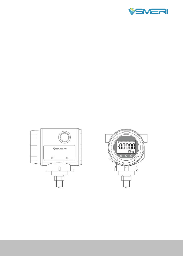
Unscrew cover of the other side.
Without display With display
4.1 Buttons operation for transmitter without LCD display
For transmitter without LCD display, buttons S and Z on circuit board can do
below operations.
4.1.1 Reset
Ensure transmitter is electrified and under no pressure, press and hold S and
Z simultaneously for over 3 seconds, then release the buttons simultaneously;
press and hold the two buttons for about 3 seconds again, the current pressure
value will be reset.
4.1.2 Lower range value calibration (LRV changing with pressure
source)
Ensure the transmitter is electrified and pressed at lower range value (LRV),
press and hold S and Z simultaneously for over 3 seconds, then release the
two buttons at the same time; press and hold Z again for about 3 seconds, the
current pressure will be transmitter LRV, but it does not change measuring
range of the transmitter. For example: if the transmitter's range is 0~5kPa, the
current pressure is -1kPa, after executing above operation, the transmitter
range will be -1~4kPa.
4.1.2 Upper range value calibration (FRV calibrating with pressure
source)
Ensure the transmitter is electrified and under pressure of upper range value
(URV), press and hold S and Z at same time for over 3 seconds, then release
- 4 -
them at the same time; press and hold S again for about 3 seconds, the current
pressure will be URV, but it will not change transmitter LRV. For example:
the transmitter's range is 0~5kPa, the current pressure is 4kPa, after executing
above operation, the transmitter range becomes 0-4kPa.
4.2 Button instruction of transmitter with LCD display
If transmitter is with LCD display, it can not only fulfil operations 4.1, but
also parameters configuration by the three buttons on LCD display.
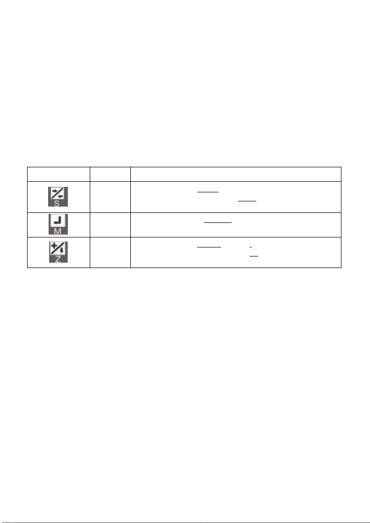
4.2.1 Buttons Description
Button pic
Name
Function
S
In menu state, it is Return function;
In parameter setting state, it is Shift function; the button also
has the function of button S of 4.1 item.
M
Menu and parameter Confirm function.
Z
In menu state, it is Choose function;
In parameter setting state, it means +1;
The button also has function of button Z of 4.1 item.
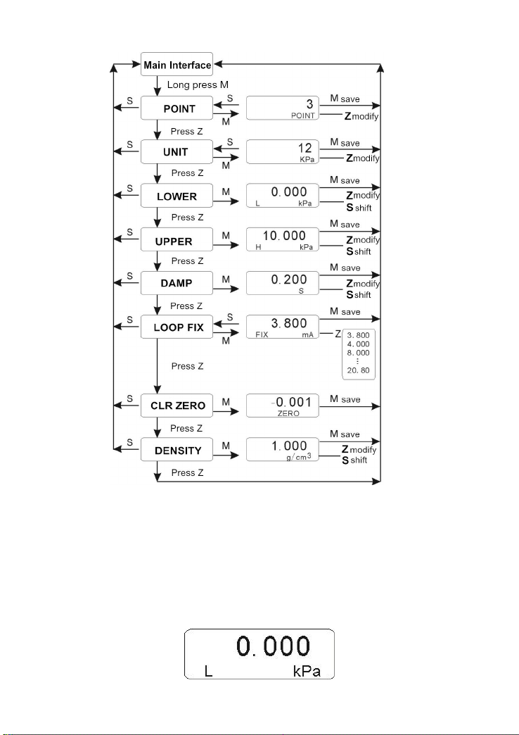
4.2.2 Menu structure
When transmitter is electrified, long press M button to enter parameter setting
menu.
- 5 -
4.2.3 Configuring Examples
Change LRV
At main measurement interface, long press M to enter menu selection
mode, the display blinks POINT. If press S at this time, it will exit
setting and return to measurement display state;
Press Z till the LCD shows LOWER with blink, press M to start LRV
setting;

- 6 -
Then press S to change the modifying digit, press Z to +1 for the
selected digit; press M to save the setting and return to the main
measurement interface.
Note:
1. When decimal point is selected, it will flash, press Z to move the decimal
point circularly;
2. When negative sign is selected, it will flash, press Z to change the negative
sign state; when the negative sign is valid, it will speed up flashing; if it is
invalid, flashing slows down.
4.2.4 Density Setting Instruction
Density setting is only valid for units m and mm. Main variable value,
LRV and URV can be calculated as per below formula.
When unit is m:
h=P/(ρ*g)
h: height (unit: m);
P: measuring pressure value (unit:kPa);
ρ:density (unit:g/cm³);
g: 9.80665;
When unit is mm:
h=1000*P/(ρ*g)
h: height(unit:mm);
P: measuring pressure value (unit:kPa);
ρ:density (unit:g/cm³);
g: 9.80665
4.2.5 Reset to defaults
If error or disorder occurs during transmitter parameters setting, users can use
buttons on display to reset to defaults, and reset parameters according to the
actual usage conditions. Detailed method is as below:
Enter damping time (DAMP) parameter setting state, set damp as

"801.xx" by buttons (x: any digit);
Press M to confirm, transmitter will be reset to defaults;
The damping time "801.xx" is actually not saved because the valid
range of damping time is 0-64 seconds;
Reset parameters according to actual usage conditions.
4.2.6 Additional Notes
When transmitter is in parameter setting state, if no button is pressed for
about 30 seconds, it will automatically return to main measuring status, the
parameters displayed will not be saved.
SMERI s.r.l.
Via Mario Idiomi 3/13
I - 20057 Assago MI
Tel. +39 02 539 8941
E-mail: [email protected] - www.smeri.com
SMERI_PT4S_SMART_MO_EN_03_23
Table of contents
Popular Transmitter manuals by other brands


Sunstech
Sunstech FTM300BTUSB user manual

RadioLink
RadioLink RC8X Firmware Upgrade Instructions

Hubbell
Hubbell Full-Size Transmitter 31.310 Spec sheet

Williams Sound
Williams Sound Personal PA PPA T36 Instructions for use and care

BD Sensors
BD Sensors DX14A-DMK 456 operating manual

BWI Eagle
BWI Eagle AIR-EAGLE SR PLUS TX Product information bulletin

Dometic
Dometic Waeco PerfectView VT100DIG Installation and operating manual

Vaisala
Vaisala HUMICAP HMT360 SERIES Safety guide

CYP
CYP COH-RX2 Operation manuals

Silicon Laboratories
Silicon Laboratories Si4010 Series user guide

Comnet
Comnet FVR1021 Series Installation and operation manual

Dwyer Instruments
Dwyer Instruments IEF Series Specifications-installation and operating instructions