Smitec ICOS 3110 User manual
ICOS 3110-FB servomotor Installation, use and maintenance manual - EN
Ver. 1.00 1
Smitec S.p.A., viale Vittorio Veneto 4, 24016 San Pellegrino Terme (BG), Italy, www.smitec.it
Installation, use and maintenance manual
SERVOMOTOR WITH
INTEGRATED DRIVE
ICOS 3110
BEFORE STARTING UP THE SERVOMOTOR ICOS 3110, CAREFULLY READ THIS
MANUAL AND FOLLOW ALL INSTRUCTIONS, IN ORDER TO ENSURE MAXIMUM
SAFETY
The technical data and the drawings in this manual might have been modified later; always
refer to the latest version.

ICOS 3110-FB servomotor Installation, use and maintenance manual - EN
Ver. 1.00 2
Summary
1 Preface ....................................................................................................................................................... 3
2 General warnings ...................................................................................................................................... 4
3 Safety instructions .................................................................................................................................... 6
3.1 General information ............................................................................................................................ 6
3.2 Precautions during handling and assembly ........................................................................................ 6
3.3 Precautions against risk of Electric Shock .......................................................................................... 7
3.4 Precautions against hot components .................................................................................................. 7
3.5 Residual risks ...................................................................................................................................... 8
3.6 Limitations of use ................................................................................................................................ 8
4 Data sheet .................................................................................................................................................. 9
4.1 Description .......................................................................................................................................... 9
4.2 Reference documents ....................................................................................................................... 10
4.3 Technical data ................................................................................................................................... 10
4.3.1 Mechanical characteristics ........................................................................................................ 10
4.3.2 Environmental specifications .................................................................................................... 11
4.3.3 Power supply ............................................................................................................................ 12
4.3.4 Digital inputs ............................................................................................................................. 12
4.3.5 Configurations / order codes ..................................................................................................... 12
4.4 Accessories ....................................................................................................................................... 13
4.5 Electromagnetic compatibility (EMC) ................................................................................................ 13
4.6 Mechanical specifications ................................................................................................................. 14
4.6.1 Weight ....................................................................................................................................... 14
4.6.2 Size ........................................................................................................................................... 14
5 Installation and start-up ......................................................................................................................... 15
5.1 Preliminary operations ...................................................................................................................... 15
5.2 Installation mode ............................................................................................................................... 16
5.3 Mechanical assembly ........................................................................................................................ 17
5.3.1 Fastening .................................................................................................................................. 17
5.3.2 Torque transmission ................................................................................................................. 18
5.4 Connections and LEDs ..................................................................................................................... 19
5.4.1 DC-bus power supply - J3 ......................................................................................................... 20
5.4.1.1 Conductors and protective devices ................................................................................... 23
5.4.1.1.1 Protection for UL applications ................................................................................... 23
5.4.1.1.2 Protection for other applications ............................................................................... 23
5.4.2 FlxIO field bus - J1 .................................................................................................................... 25
5.4.3 Auxiliary power supply 24V - J4 ................................................................................................ 27
5.4.4 Digital inputs and power supply with 24V output - J2 ............................................................... 29
5.4.4.1 24V digital inputs .............................................................................................................. 30
5.4.5 LEDs ......................................................................................................................................... 31
5.4.5.1 References signaling LEDs (STS) .................................................................................... 31
5.4.5.2 LED1 behavior .................................................................................................................. 32
5.4.5.3 LED2 and LED3 behavior ................................................................................................. 32
5.4.6 Installation criteria for UL certification ....................................................................................... 33
5.5 Addressing ........................................................................................................................................ 34
5.5.1 Manual addressing .................................................................................................................... 34
6 Firmware upgrade ................................................................................................................................... 36
7 Storage ..................................................................................................................................................... 37
8 Maintenance ............................................................................................................................................ 38
9 Disposal and demolition ......................................................................................................................... 39
10 Analytical index ..................................................................................................................................... 40

ICOS 3110-FB servomotor Installation, use and maintenance manual - EN
Ver. 1.00 3
1 Preface
This manual provides all necessary information for the installation, use and maintenance of the servodrive
ICOS 3110.
The instructions included in this manual are addressed to the following professionals:
The present instructions must be made available to all the above individuals.
User User is a person, a company or an institution that buys the equipment and
uses it for the purposes it was designed for.
User/operator User or operator is a person authorized by the user to operate on the equip-
ment.
Specialized personnel It refers to all persons with specific competence, able to recognize and avoid
the dangers deriving from the use of the equipment.

ICOS 3110-FB servomotor Installation, use and maintenance manual - EN
Ver. 1.00 4
2 General warnings
These assembly instructions are an integral part of the equipment, and must be kept for future reference until
it decomissioned.
The user should be informed that the present instructions reflect the state of the art at the moment when the
equipment was sold; they will remain fully acceptable despite subsequent upgrades based on new technical
update.
In order to make the manual consultation easier, the following symbols have been adopted:
DO NOT USE THE EQUIPMENT, NOR MAKE ANY INTERVENTION BEFORE INTE-
GRALLY READING AND UNDERSTANDING THIS MANUAL.
IN PARTICULAR, ADOPT ALL SAFETY PRECAUTIONS AND PRESCRIPTIONS INDICATED IN THIS
MANUAL.
THE EQUIPMENT MUST NOT BE USED FOR PURPOSES DIFFERENT THAN THE ONES DESCRIBED
IN THIS MANUAL; SMITEC S.p.A. SHALL NOT BE HELD RESPONSIBLE FOR ANY DAMAGES, IN-
CONVENIENCES OR ACCIDENTS DUE TO THE NON-COMPLIANCE WITH THESE PRESCRIPTIONS.
Indication of “PROHIBITED ACTION”.
The symbol “DANGER” is used when non-compliance with the prescriptions or misuse may
cause serious injuries.
The symbol “DANGER FROM HOT SURFACES” is used when non-compliance with the
prescriptions or misuse may cause serious injuries.
The symbol “DANGER FROM ELECTRICAL SHOCK” is used when non-compliance with
the prescriptions or misuse may cause serious injuries.
ICOS 3110-FB servomotor Installation, use and maintenance manual - EN
Ver. 1.00 5
The safety prescriptions aim at establishing a series of behaviors and obligations to be complied with, while
performing the activities described later on in this manual.
These prescriptions constitute the prescribed method of operating the device, in a way that is safe for person-
nel, equipments and environment.
The symbol “USE OF INDIVIDUAL PROTECTIONS” means that protective gloves must be
worn.
The symbol “USE OF INDIVIDUAL PROTECTIONS” means that protective glasses must be
worn.
Indication of “INFORMATION OF PARTICULAR RELEVANCE”.
ICOS 3110-FB servomotor Installation, use and maintenance manual - EN
Ver. 1.00 6
3 Safety instructions
3.1 General information
3.2 Precautions during handling and assembly
Do not install or use the equipment before integrally reading and understanding this manual.
In case of difficulties of interpretation, contact SMITEC technical service.
It is absolutely forbidden to use the equipment for different purposes than the ones de-
scribed in this manual. The technical data and the drawings in this manual might have been
modified later; always refer to the latest version. All upgrades can be requested to SMITEC
S.p.A. directly.
Make sure that the personnel is qualified and adequately informed about the risks he may
run and how to avoid them.
Servodrive ICOS 3110 can be used only after classifying the final machine operating zone
and after checking the safety levels, which must comply with the machine safety levels.
Use adequate tools during the assembly, in order to avoid crushing or abrasions.
Metal components and sharp surfaces may cause cuts and tears. In case of contact, be very
careful and wear the personal protection equipment.

ICOS 3110-FB servomotor Installation, use and maintenance manual - EN
Ver. 1.00 7
3.3 Precautions against risk of Electric Shock
3.4 Precautions against hot components
WARNING
AVERTISSEMENT
The power supply connector is subject to high voltage during the servodrive operation; be
careful (danger of Electric Shock).
During installation and maintenance, disconnect the device from the mains power supply.
Risk of Electric Shock.
Some components (such as the aluminium heat sink) are made of conductive materials.
They must be safely connected to the protective conductor (PE/Ground) by using the spe-
cific terminal strips, in order to avoid Electric Shock.
Never use the device if it is partially or totally disassembled. Risk of Electric Shock and/or
damages to people and properties.
The parts of the apparatus can reach an extremely high temperature in operating mode or
post-operation; take particular care not to touch the parts of the equipment in these cases,
or use special protections and precautions during handling: Hot Surface, Risk of Burn.
Les pièces de l'appareil peuvent atteindre une température extrêmement élevée en mode
de fonctionnement ou post-opération; veillez particulièrement à ne pas toucher les pièces
de l'équipement dans ces cas, ou utilisez des protections et des précautions spéciales lors
de la manipulation: Surface Chaude, Risque de Brûlure.
The manufacturer of a servodrive ICOS 3210 must take all precautions in order to avoid the
operator's contact with hot components, to prevent the risk of burning.
ICOS 3110-FB servomotor Installation, use and maintenance manual - EN
Ver. 1.00 8
3.5 Residual risks
3.6 Limitations of use
The apparatus generates an electromagnetic field during operation. Danger for people with
pacemakers, metal prostheses or hearing aids.
The servodrive ICOS 3110 is not safety device; do not rely on them to carry out safety func-
tions (for example: safe stop, safe reduced speed, etc...).
The operating temperature range of the servodrive is 0 ÷ 55°C; the operating temperature
range at rated current (without derating) is 0 ÷ 45°C.

ICOS 3110-FB servomotor Installation, use and maintenance manual - EN
Ver. 1.00 9
4 Data sheet
4.1 Description
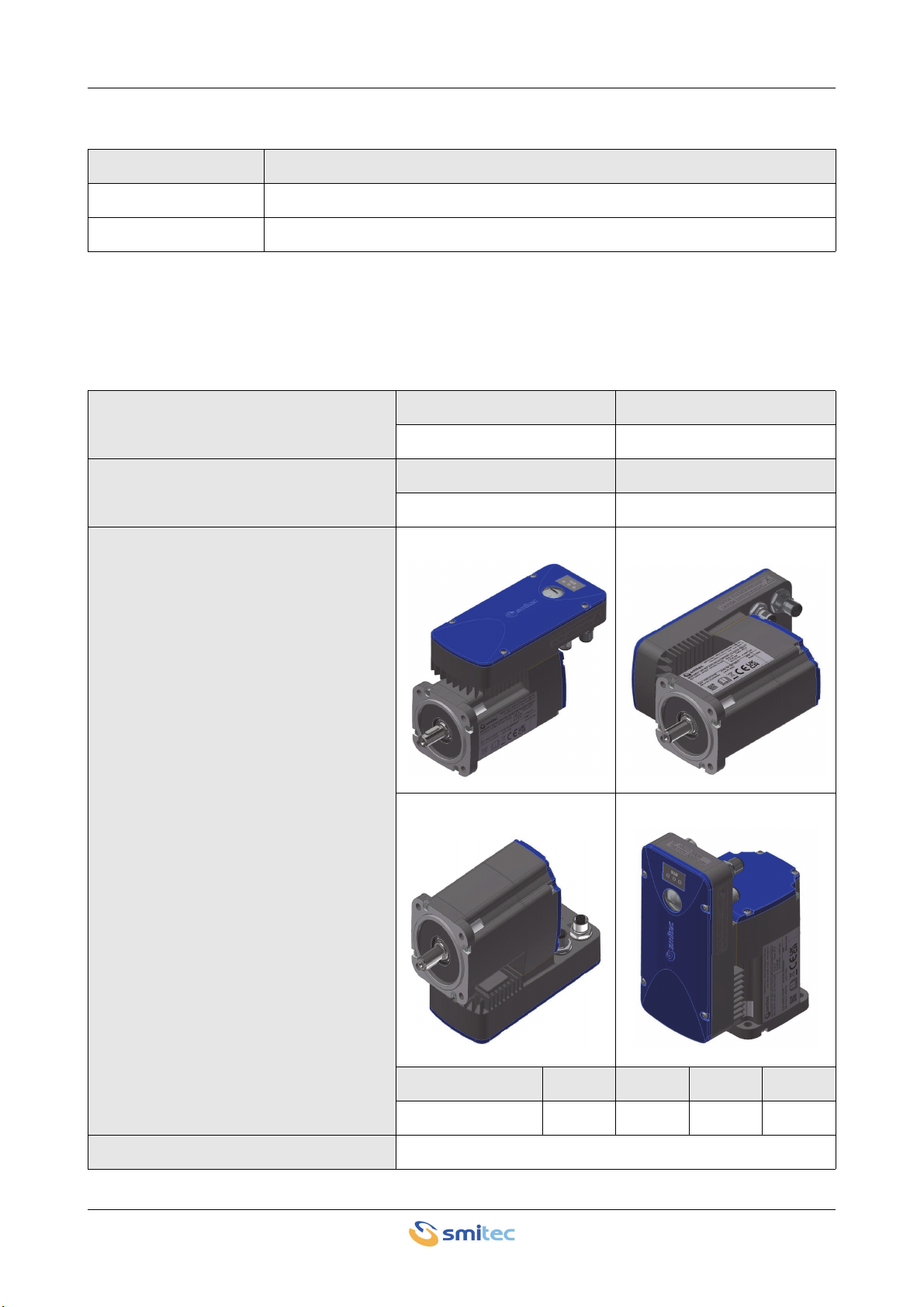
The servomotor ICOS 3110 is brushless AC servomotor (BLAC) with integrated servodrive. The aluminium
case enables heat dissipation without needing external fans (“fanless”), forming an extremely compact and re-
liable unit. The motor is equipped with an incremental encoder.
The control unit, based on a microprocessor, controls an intelligent IGBT module (IPM), in order to ensure a
sophisticated, reliable control of the motor. This is possible also thanks to the FlxIO field bus, based on
insulated, real-time RS 485 serial port. It is possible to check the speed, the position and the motor torque, in
a very flexible way. It is possible to upgrade the firmware via field bus, in a quick way and without needing
external connections. The field bus insulation ensures better immunity to EMC interferences and improves
electrical ruggedness. The 32-bit microcontroller ensures a detailed diagnosis of the device, which is very
useful during the system development phase.
To ensure maximum flexibility of use, the ICOS 3110-FB servomotor is equipped with 2 digital inputs, in order
to allow interfacing with standard sensors.
Front view
Rear view
ICOS 3110-FB servomotor Installation, use and maintenance manual - EN
Ver. 1.00 10
4.2 Reference documents
4.3 Technical data
4.3.1 Mechanical characteristics
Code Description
DK400197 Use and programming manual ICOS 3XXX
DK400076 FLXIO / FLXMOD integration manual
Delivered torque
Rated torque Inrush torque
0.65 Nm 1.96 Nm
Rotation speed
Rated speed Maximum speed
3000 rpm 3250 rpm
Mechanical power supplied to the shaft
(it depends on the assembly position,
as indicated in the pictures A, B, C and
D)
AB
CD
A (kW) B (kW) C (kW) D (kW)
EM700043 0.19 0.20 0.20 0.19
Rotor moment of inertia 0.40 10-4 kg·m2

ICOS 3110-FB servomotor Installation, use and maintenance manual - EN
Ver. 1.00 11
4.3.2 Environmental specifications
Shaft diameter 11 mm
Operating temperature
(Maximum air temperature)
0° ÷ +45°C with full-load operation
0° ÷ +55°C with derating of the delivered torque
Environment of use Use in Pollution degree 2 Environment
Degree of protection IP65
Air humidity during operation 5 ÷ 85% not condensing
Storage temperature -25 ÷ +55°C
Air humidity during stocking 5 ÷ 95%
Air humidity during transportation 5 ÷ 95%
Maximum altitude
1000 m a.s.l. at rated output current
2000 m a.s.l. with current derating
Output current derating as a function of
altitude
Derating of the delivered torque as
compared to the rated torque as a func-
tion of the environment temperature for
motors EM700043.
The possible assembly positions, pre-
viously described at paragraph 4.3.1
(Mechanical features) are indicated in
the legend of the picture.
Derating of the torque delivered with
respect to the nominal value [%]

ICOS 3110-FB servomotor Installation, use and maintenance manual - EN
Ver. 1.00 12
For each of the 4 possible installation positions of the servomotor ICOS 3110 shown in paragraph 4.3.1, the
maximum torque values that can be supplied continuously (duty S1) both at 45°C and at 55°C (derating) are
declared in the following table.
Therefore, if it is possible, during the installation of the servomotor ICOS 3110, it is advisable to fix the device
in position B, which has resulted to be the best performing among the 4 possible configurations.
4.3.3 Power supply
4.3.4 Digital inputs
4.3.5 Configurations / order codes
Up to date we defined some standard configurations of servodrives, with an order code and a number made of
4 figures and 2 letters, called “Type”, indicating the series, the maximum current, the hardware version, the
communication bus and the controlled motors. The type is indicated on the servodrive label.
Maximum torque at 45°C Maximum torque at 55°C
Position A 0.60 Nm 0.15 Nm
Position B 0.65 Nm 0.20 Nm
Position C 0.65 Nm 0.15 Nm
Position D 0.60 Nm 0.15 Nm
Mains voltage 325 VDC ± 15%
Maximum short-circuit current 5 kA at the installation point
Mains power supply max. absorption 0.7A DC
Auxiliary mains voltage 24 VDC -15 ÷ +20%; ripple max 5% of the rated value
Auxiliary mains power supply max. ab-
sorption 24V_MAIN 70 mA
Max. dispensing auxiliary power supply 24V_I/O (protection 0.5A) 500 mA
Number of inputs 2 digital inputs
Type 24 V digital inputs, compatible with type 1 and type 3, accord-
ing to IEC 61131-2
Input sampling interval 1 ms min
Order code Model Description
EM700043 ICOS 3110-FB- Ø70 0.65Nm 230V 3000rpm incremental encoder

ICOS 3110-FB servomotor Installation, use and maintenance manual - EN
Ver. 1.00 13
4.4 Accessories
The following table lists the accessories of the servodrive ICOS 3110, including their order code:
4.5 Electromagnetic compatibility (EMC)
The servodrives/inverters comply with EN IEC 61800-3 requirements for installation in environment 2
(“Second environment”), category C3. The servodrive must be installed according to the installation criteria
described in the manual of the power supply unit ICOS-PS 31XX. The manual code is DK400183.
The servodrive installation can be considered as adequate when it complies with the installation criteria of its
power supply unit (ICOS-PS) and no more than six servodrives (ICOS) are installed downstream.
The installer shall make sure that the device meets the standard requirements (EN IEC 61800-3 for the instal-
lation in environment 2 “Second environment”, category C3).
Order code Item
KZ010628 DC bus power supply unit ICOS-PS 3162
EP200328 Push-pull connector for the main power supply
KF131326 Connector with termination resistor for FlxIO bus, type M12

ICOS 3110-FB servomotor Installation, use and maintenance manual - EN
Ver. 1.00 14
4.6 Mechanical specifications
4.6.1 Weight
The following table indicates the weight of the different models:
4.6.2 Size
Type Weight (kg)
EM700043 1.6 kg

ICOS 3110-FB servomotor Installation, use and maintenance manual - EN
Ver. 1.00 15
5 Installation and start-up
5.1 Preliminary operations
Before starting up the device, make the following checks:
• Check the perfect integrity of the device and its components.
• Make sure that all manuals necessary for installation are available.
• Read this manual integrally.
WARNING
AVERTISSEMENT
WARNING
AVERTISSEMENT
Metal parts and all "live" parts can under certain conditions cause cuts and tears. Pay par-
ticular attention in case of contact and use suitable personal protective equipment (PPE).
Les pièces métalliques et toutes les pièces sous tension peuvent, dans certaines condi-
tions, provoquer des coupures et des déchirures. Portez une attention particulière en cas
de contact et utilisez un équipement de protection individuelle (EPI) approprié.
Use adequate tools during the assembly, in order to avoid crushing or abrasions.
Lors du montage de l’appareil, utilisez des outils appropriés pour éviter tout risque de bles-
sure, d’écrasement, d’abrasion, etc.
ICOS 3110-FB servomotor Installation, use and maintenance manual - EN
Ver. 1.00 16
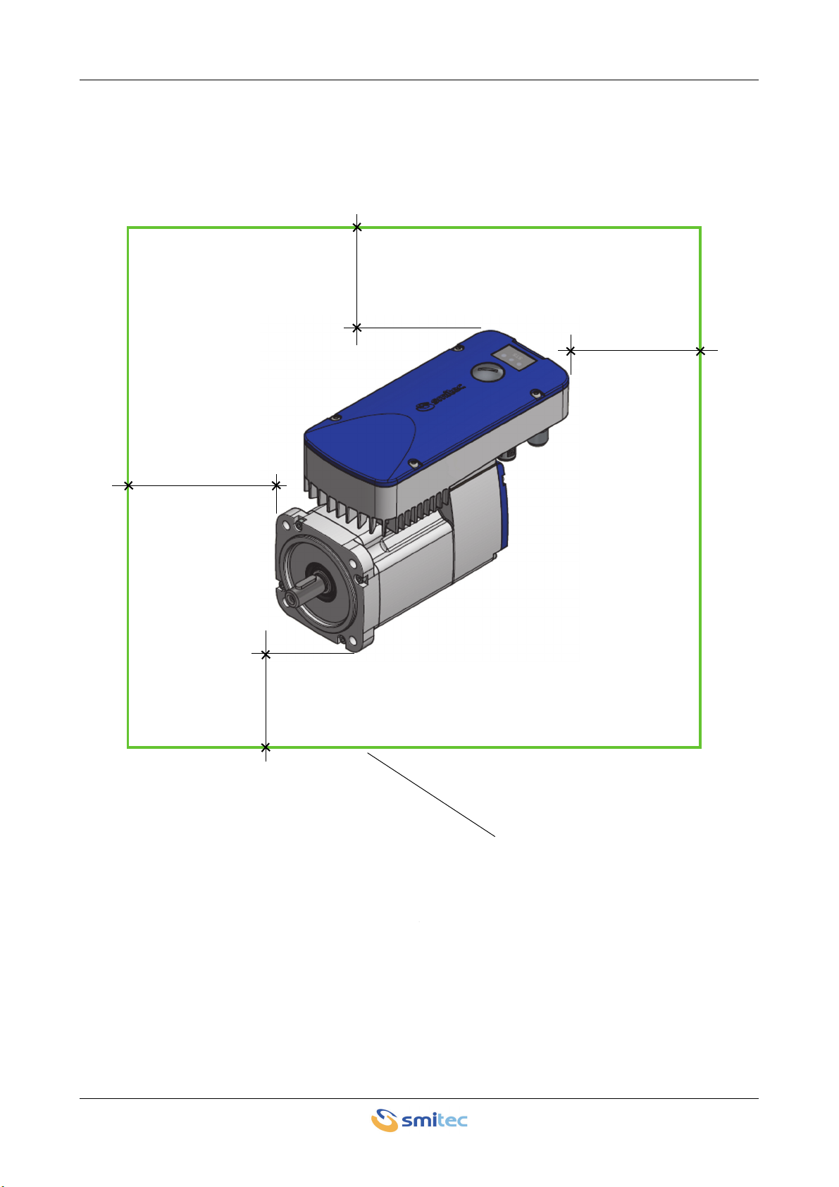
5.2 Installation mode
During the installation of the device, the upper and lower part and the side parts must have a free space of at
least 100 mm compared to other electronic and / or mechanical components.
100 mm
100 mm
Other components
100 mm
100 mm
ICOS 3110-FB servomotor Installation, use and maintenance manual - EN
Ver. 1.00 17
5.3 Mechanical assembly
5.3.1 Fastening
Tighten the flange with steel bolts, 8.8 grade or higher grade. The recommended tightening torque is indicated
in the following table, which refers to new bolts with not lubricated threads.
Reduce the tightening torque if the threads are lubricated (max. reduction 20% with MoS2 lubricant) Use flat
washers for the bolts. In case of strong vibrations and/or shock loads, use Grover washers or apply
threadlocker paste (Loctite 243 type or equivalent type).
Make sure the bearing surface is clean and flat (no dents or scratches, etc...), in order to avoid misalignment.
THREAD SIZE TIGHTENING TORQUE [Nm]
M5 6
During the servodrive assembly, always wear the personal protective equipment (PPE).

ICOS 3110-FB servomotor Installation, use and maintenance manual - EN
Ver. 1.00 18
5.3.2 Torque transmission
The torque is transmissible with direct coupling or with belt or gears.
In case of direct coupling, try to reduce the axial and radial misalignment which would cause an additional
pressure on bearings. This would considerably reduce their life and would cause vibrations. The misalignment
can be measured by means of a centesimal comparator. The misalignment limit is equal to 0.03 mm both in
radial and axial sense.
In case of belts, make sure that the motor shaft is perfectly parallel to the pulley axis. The pinion and the
pulley must be aligned, in order to avoid undesired axial loads on the bearings and heavy wear of the drive
belt. The belt tensioning must comply with the manufacturer's instructions and must not cause excessive
radial load on the bearing, which would reduce its life.
In case of gears, observe their distance during the motor assembly. If you use helical gears, make sure the
axial load does not damage the motor bearing. Check the radial load generated by the gears (especially with
large pressure angles), in order to avoid a strong reduction of the bearing fatigue life. When assembling the
pinion on the shaft, avoid radial stress to the motor bearing by using adequate tools.
For further information about the calculation of the bearings fatigue life depending on the load and on the rota-
tion speed, please refer to Standard ISO 281.

ICOS 3110-FB servomotor Installation, use and maintenance manual - EN
Ver. 1.00 19
5.4 Connections and LEDs
All connections of servodrive ICOS 3110 are ensured by removable connectors; the following picture shows
the connectors position:
The following table describes the function of each connector:
Connections
Code Description
J1 Fieldbus - FlxIO
J2 Digital inputs
J3 DC-bus main power supply
J4 24Vdc auxiliary power supply and parking brake input (where provided)
J2
J1
J4
J3
ICOS 3110-FB servomotor Installation, use and maintenance manual - EN
Ver. 1.00 20
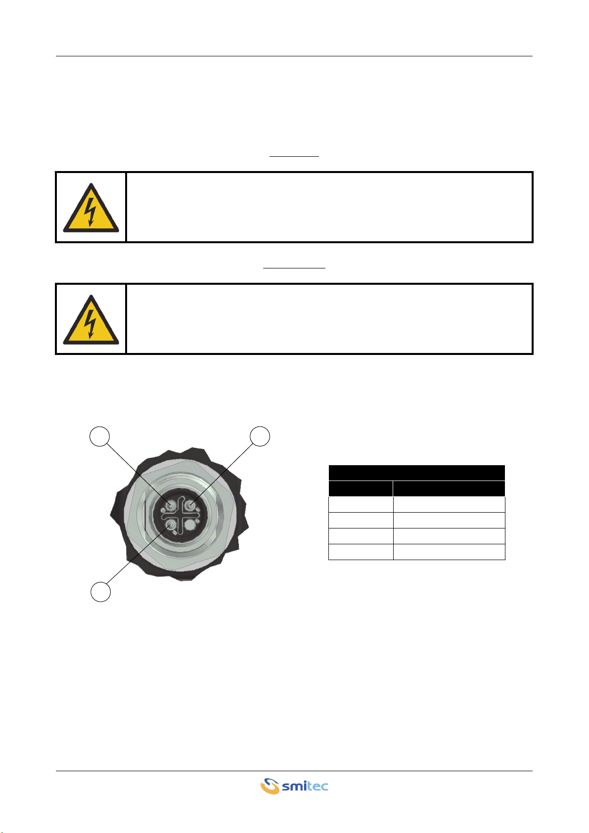
5.4.1 DC-bus power supply - J3
These are the connections of the main power supply (DC bus), with corresponding connection of the protection
earth (PE/Ground).
CAUTION
ATTENTION
The following picture shows the connector and the pin configuration:
Large capacitors inside the device. Risk of Electric Shock; wait at least No. 600 seconds (10
minutes) after disconnecting power. Do not connect or disconnect cable and connectors be-
fore that time.
Hautes capacités présentes à l'intérieur de l'appareil. Risque de choc électrique; attendez
au moins 600 secondes (10 minutes) après la mise hors tension. Les câbles et les connec-
teurs ne doivent pas être connectés ou déconnectés avant la fin du temps indiqué.
4
1
3
Main power supply
Pin Signal
1 B+ (positive)
2NC
3 B- (negative)
4 PE (Ground)
Table of contents
Popular Engine manuals by other brands


SkyReach
SkyReach BushCat Maintenance manual

AGCO Power
AGCO Power 33 Workshop service manual

Greaves
Greaves 3G11 Series Operation and maintenance manual

HO HSING
HO HSING i70M Series Operation manual

Applied Motion Products
Applied Motion Products TSM17C Hardware manual

Siemens
Siemens SIMOTICS S-1FK7 DYA Generation 2 operating instructions


