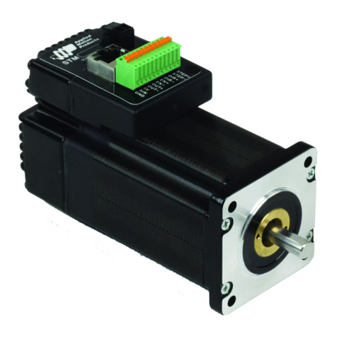
Applied Motion Products TSM17C User manual

TSM17C
Integrated Step-Servo Motor
Hardware Manual
Rev. A

2
Rev. A
920-0085
TSM17C Hardware Manual
Contents
1 Introduction.................................................................................. 3
1.1 Features.............................................................................................3
1.2 Block Diagram ...................................................................................4
1.3 Safety Instructions .............................................................................5
2 Getting Started ............................................................................ 6
2.1 Installing Software .............................................................................6
2.2 Mounting the Hardware .....................................................................6
2.3 Choosing a Power Supply .................................................................7
2.3.1 Voltage ..................................................................................................7
2.3.2 Regeneration Clamp ..............................................................................7
2.3.3 Current ...................................................................................................8
3 Installation/Connections ............................................................ 12
3.1 Connecting the Power Supply .........................................................12
3.2 Connecting the TSM17C Communications......................................13
3.2.1 Node ID ................................................................................................14
3.2.2 Setting the Bitrate.................................................................................14
3.3 Inputs and Outputs ..........................................................................15
3.3.1 Connector Pin Diagram ........................................................................15
3.3.2 X1 & X2 Digital Input ............................................................................16
3.3.3 X3/X4/X5/X6 Digital Input.....................................................................17
3.3.4 X7/X8 Digital Input................................................................................18
3.3.5 Programmable Output Y1/Y2/Y3..........................................................19
3.3.6 Programmable Output Y4.....................................................................20
4 Troubleshooting ......................................................................... 21
5 Reference Materials .................................................................. 22
5.1 Torque-Speed Curves......................................................................22
5.2 Mechanical Outlines ........................................................................23
5.3 Technical Specications...................................................................24
6 Contacting Applied Motion Products.......................................... 25
Model
Communications
RS-232 CANopen
TSM17C-1CG
TSM17C-2CG
TSM17C-3CG

3Rev. A
920-0085
TSM17C Hardware Manual
1 Introduction
Thank you for selecting the Applied Motion Products TSM17C Integrated
Motor.The TSM line of integrated step-servo motors combines servo
technology with an integrated motor to create a product with exceptional
features and broad capabilities. We hope our commitment to performance,
quality and economy will result in a successful motion control project.
1.1 Features
• Programmable, Digital servo driver and motor in an integrated package
• Operates from a 12 to 48 volt DC power supply
• Control Modes:
CANopen(compliant CiA 402)
* Prole Torque
* Prole Velocity
* Prole Position
* Homing
Q Programing
* Execute stored Q programs via Applied Motion Products specic CANopen
objects
• Communications:
CANopen & RS-232
• 5000 line (20,000 counts/rev) encoder feedback
• Available torque:
TSM17C-1CG: Up to 0.28 N•m Continuous(0.35 N•m Boost)
TSM17C-2CG: Up to 0.42 N•m Continuous(0.52 N•m Boost)
TSM17C-3CG: Up to 0.52 N•m Continuous(0.68 N•m Boost)
• I/O:
8 optically isolated digital inputs,
with adjustable bandwidth digital noise rejection lter, 5 to
24 volts
4 optically isolated digital output, 30V/100 mA max.
1 analog input,0 to 5 volts
• Technological advances:
Full servo control, Closed loop
Efcient, Accurate, Fast, Smooth
Intelligent, Compact

4
Rev. A
920-0085
TSM17C Hardware Manual
1.2 Block Diagram
Block Diagram
MOSFET
PWM
Power
Amplifier
12 - 48 VDC
External
Power Supply
Voltage
Temp
Detect
Over
Current
Detect
motor
encoder
5 Volt DC
Power Supply
DSP
Driver
Controller
3.3VDC
Internal
Logic
Supply
TSM17C
I/O Connector
+
+5VDC (100mA max)
GND
Status
AIN
Optical
Iso
RS-232 & CANopen
Comm
Conn
Power
Conn
GND
+5V
RS-232
RXD,+5V,TXD,GND,GND
and
CANopen
CANH, CANL, GND
-
X1
X2
X3
X4
X5
X6
X7
X8
Y1
Y2
Y3
Y4
Optical
ISO

5Rev. A
920-0085
TSM17C Hardware Manual
1.3 Safety Instructions
Only qualied personnel should transport, assemble, install, operate, or maintain this equipment.
Properly qualied personnel are persons who are familiar with the transport, assembly, installation,
operation, and maintenance of motors, and who meet the appropriate qualications for their jobs.
To minimize the risk of potential safety problems, all applicable local and national codes regulating
the installation and operation of equipment should be followed. These codes may vary from area
to area and it is the responsibility of the operating personnel to determine which codes should be
followed, and to verify that the equipment, installation, and operation are in compliance with the
latest revision of these codes.
Equipment damage or serious injury to personnel can result from the failure to follow all applicable
codes and standards. Applied Motion Products does not guarantee the products described in
this publication are suitable for a particular application, nor do they assume any responsibility for
product design, installation, or operation.
• Read all available documentation before assembly and operation. Incorrect handling of the
products referenced in this manual can result in injury and damage to persons and machinery.
All technical information concerning the installation requirements must be strictly adhered to.
• It is vital to ensure that all system components are connected to earth ground. Electrical safety
is impossible without a low-resistance earth connection.
• This product contains electrostatically sensitive components that can be damaged by incorrect
handling. Follow qualied anti-static procedures before touching the product.
• During operation keep all covers and cabinet doors shut to avoid any hazards that could
possibly cause severe damage to the product or personal health.
• During operation, the product may have components that are live or have hot surfaces.
• Never plug in or unplug the Integrated Motor while the system is live. The possibility of electric
arcing can cause damage.
Be alert to the potential for personal injury. Follow recommended precautions and safe operating
practices emphasized with alert symbols. Safety notices in this manual provide important
information. Read and be familiar with these instructions before attempting installation, operation,
or maintenance. The purpose of this section is to alert users to the possible safety hazards
associated with this equipment and the precautions necessary to reduce the risk of personal injury
and damage to equipment. Failure to observe these precautions could result in serious bodily
injury, damage to the equipment, or operational difculty.
6
Rev. A
920-0085
TSM17C Hardware Manual
2 Getting Started
The following items are needed:
• a 12 - 48 Volt DC power supply, see the section below entitled “Choosing a Power Supply” for
help in choosing the right one
• a small at blade screwdriver for tightening the connectors (included)
• a PC running Microsoft Windows XP, Vista, or Windows 7 or 8
• an Applied Motion Products programming cable for RS-232 interface and another cable for
CANopen daisy-chain(both included with TSM17C
2.1 Installing Software
Before utilizing the TSM17C Integrated Step-Servo Motor and Step-Servo Quick Tuner Software in
an application, the following steps are necessary:
• Install the Step-Servo Quick Tuner software from the Applied Motion Products website.
• Connect the drive to the PC using the programming cable.
• Connect the drive to the power supply. See instructions below.
• Launch the software by clicking Start...Programs...Applied Motion Products.
• Apply power to the drive.
• The software will recognize the drive and display the model and rmware version. At this point,
it is ready for use.
2.2 Mounting the Hardware
As with any step motor, the TSM17C must be mounted so as to provide maximum heat sinking
and airow. Keep enough space around the Integrated Motor to allow for airow.
• Never use the drive where there is no airow or where other devices cause the
surrounding air to be more than 40°C (104°F).
• Never put the drive where it can get wet.
• Never use the drive where metal or other electrically conductive particles can inltrate
the drive.
• Always provide airow around the drive.

7Rev. A
920-0085
TSM17C Hardware Manual
2.3 Choosing a Power Supply
The main considerations when choosing a power supply are the voltage and current requirements
for the application.
2.3.1 Voltage
The TSM17C is designed to give optimum performance between 24 and 48 Volts DC. Choosing
the voltage depends on the performance needed and motor/drive heating that is acceptable and/
or does not cause a drive over-temperature. Higher voltages will give higher speed performance
but will cause the TSM17C to produce higher temperatures. Using power supplies with voltage
outputs that are near the drive maximum may signicantly reduce the operational duty-cycle.
The extended range of operation can be as low as 10 VDC minimum to as high as 55 VDC
maximum. When operating below 18 VDC, the power supply input may require larger capacitance
to prevent under-voltage and internal-supply alarms. Current spikes may make supply readings
erratic. The supply input cannot go below 10 VDC for reliable operation. Absolute minimum power
supply input is 10 VDC. If the Input supply drops below 10 VDC the low voltage alarm will be
triggered. This will not fault the drive.
Absolute maximum power supply input is 55 VDC at which point an over-voltage alarm and fault
will occur. When using a power supply that is regulated and is near the drive maximum voltage
of 55 VDC, a voltage clamp may be required to prevent over-voltage when regeneration occurs.
When using an unregulated power supply, make sure the no-load voltage of the supply does not
exceed the drive’s maximum input voltage of 55 VDC.
2.3.2 Regeneration Clamp
If a regulated power supply is being used, there may be a problem with regeneration. When a
load decelerates rapidly from a high speed, some of the kinetic energy of the load is transferred
back to the power supply, possibly tripping the over-voltage protection of a regulated power
supply, causing it to shut down. This problem can be solved with the use of an Applied Motion
Products RC880 Regeneration Clamp. It is recommended that an RC880 initially be installed in an
application. If the “regen” LED on the RC880 never ashes, the clamp is not necessary.
RC880 Regen Clamp
LEDs
Green - Power
Red - Regen on

8
Rev. A
920-0085
TSM17C Hardware Manual
2.3.3 Current
The maximum supply currents required by the TSM17C are shown in the charts below at different
power supply voltage inputs. The TSM17C power supply current is lower than the winding currents
because it uses switching ampliers to convert a high voltage and low current into lower voltage
and higher current. The more the power supply voltage exceeds the motor voltage, the less
current will be required from the power supply.
It is important to note that the current draw is signicantly different at higher speeds depending
on the torque load to the motor. Estimating how much current is necessary may require a good
analysis of the load the motor will encounter.
0
0.5
1
1.5
0
0.1
0.2
0.3
0.4
0 10 20 30 40 50
TSM17C-1CG 12V Power
Torque(N.m)
Speed(RPS)
Amps
Continuous
Torque
Boost
Supply Current
Full Load
No Load
0
0.5
1
1.5
0
0.1
0.2
0.3
0.4
0 10 20 30 40 50
TSM17C-1CG 24V Power
Torque(N.m)
Speed(RPS)
Amps
Continuous
Torque
Boost
Supply Current
Full Load
No Load

9Rev. A
920-0085
TSM17C Hardware Manual
0
0.5
1
1.5
0
0.1
0.2
0.3
0.4
0 10 20 30 40 50
Torque(N.m)
Speed(RPS)
TSM17C-1CG 48V Power
Amps
Continuous
Torque
Boost
Supply Current
Full Load
No Load
0
0.5
1
1.5
0
0.1
0.2
0.3
0.4
0.5
0.6
0 10 20 30 40 50
TSM17C-2CG 12V Power
Torque(N.m)
Speed(RPS)
Amps
Continuous
Torque
Boost
Supply Current
Full Load
No Load
0
0.5
1
1.5
0
0.1
0.2
0.3
0.4
0.5
0.6
0 10 20 30 40 50
TSM17C-2CG 24V Power
Torque(N.m)
Speed(RPS)
Amps
Continuous
Torque
Boost
Supply Current
Full Load
No Load

10
Rev. A
920-0085
TSM17C Hardware Manual
0
0.5
1
1.5
0
0.1
0.2
0.3
0.4
0.5
0.6
0 10 20 30 40 50
Torque(N.m)
Speed(RPS)
TSM17C-2CG 48V Power
Amps
Continuous
Torque
Boost
Supply Current
Full Load
No Load
0
0.5
1
1.5
0
0.1
0.2
0.3
0.4
0.5
0.6
0.7
0 10 20 30 40 50
Torque(N.m)
Speed(RPS)
TSM17C-3CG 12V Power
Amps
Continuous
Torque
Boost
Supply Current
Full Load
No Load
0
0.5
1
1.5
0
0.1
0.2
0.3
0.4
0.5
0.6
0.7
0 10 20 30 40 50
Torque(N.m)
Speed(RPS)
TSM17C-3CG 24V Power
Amps
Continuous
Torque
Boost
Supply Current
Full Load
No Load

11 Rev. A
920-0085
TSM17C Hardware Manual
0
0.5
1
1.5
0
0.1
0.2
0.3
0.4
0.5
0.6
0.7
0 10 20 30 40 50
Torque(N.m)
Speed(RPS)
TSM17C-3CG 48V Power
Amps
Continuous
Torque
Boost
Supply Current
Full Load
No Load

12
Rev. A
920-0085
TSM17C Hardware Manual
3 Installation/Connections
3.1 Connecting the Power Supply
Use 16 to 20-gauge wire to connect the TSM17C to a power supply. It contains an internal fuse
connected to the “+” terminal that is not user replaceable. If a user serviceable fuse is desired,
install a 6.3 amp fast acting fuse in line with the “+” power supply lead.
Be careful not to reverse the wires. Reversing the connection may open the internal
fuse on the drive and void the warranty.
Applied Motion Products offers two matched power supplies for use with the TSM17C.
A 24VDC, 150W(P/N PS150A24) and a 48VDC 320W(P/N PS320A48).
These power supplies have current over load capability making them ideal for use.
(To use with a switch power supplier, a RC880 regen must be connected in system)
The RC880 regeneration clamp is for use where regeneration from the motor may cause damage
to the drive. In these cases the RC880 is connected between the drive and power supply and
absorbs regenerated energy.
To Earth Ground
To Power Supply-
To Power Supply+
RC880
TSM
V-V+
V-V+
Vin
-
+
Vout
+
-
Power Supply

13 Rev. A
920-0085
TSM17C Hardware Manual
3.2 Connecting the TSM17C Communications
Two standard 5-pin disconnectable crimp style connectors are used for the communications
interface of TSM17C, and both of them can be used for RS-232 serial interface and CANopen
daisy-chain by different cable included with TSM17C.
CANopen Connector Diagram
The TSM17C is congured using a combination of rotary switches and an RS-232 serial link,
and then may be deployed on a distributed CANopen network. The RS-232 interface is used for
conguration, tuning, node ID setting and Q program downloading. The CANopen network should
be connected in a daisy-chain fashion, with a 120 ohm terminating resistor at each end of network.
Locate the TSM17C within 1.5 meters of the PC. Plug the DB9 connector of the communication
cable that came with the drive into the serial port of the PC. Plug the 5-pin crimp style connector
into one of the two appropriate connector on the TSM17C. Secure the cable to the PC with the
screws on the DB9 connector.
Note: If the PC does not have an RS-232 serial port, a USB Serial Converter will be needed.
You can contact Applied Motion Products to buy a USB to RS-232 converter.
The RS-232 circuitry does not have any extra electrical “hardening” and care should be taken
when connecting to the RS-232 port as hot plugging could result in circuit failure.
TXD
RXD
CAN_H
CAN_L
GND
1
.1” Spacing Spring Plug
DSUB9 Female
R termination:
Network must be terminated at each
end with a 120 ohm resistor.
n:
Cable may be made with up to 127 drive
connectors. Termination is only required
at each end.
.1” Spacing Spring Plug
n*
R termination*
120 ohm nominal
R termination*
120 ohm nominal
1
CAN_L
CAN_L
CAN_GND
CAN_GND
CAN_BUS
CAN_SHLD
CAN_SHLD
CAN_H
CAN_H
2
3
4
2
3
4
5
6
7
8
9
1
CAN_L
CAN_GND
CAN_SHLD
CAN_H
2
3
4

14
Rev. A
920-0085
TSM17C Hardware Manual
3.2.1 Node ID
Each node ID on a CANopen network must have a unique Node ID. The Node ID is congured
using a sixteen position switch on the top of the drive to set the lower four bits of the Node ID
while the upper three bits are congured by using Step-Servo Quick tuner software. CANopen
Node IDs are seven bits long, with a range of 1 - 127, or 0x01 - 0x7F in hexadecimal notation.
Node ID 0x00 is reserved in accordance with the CiA 301 specication.
3.2.2 Setting the Bitrate
The CANopen network bitrate is set by the ten position switch on the top of the drive. The bit rate
must be the same for all nodes on the CANopen network. Any changes to the bit rate require
either a power cycle or a CANopen reset command to take effect.
SW1 Bit Rate
0 1 Mbps
1 800 kbps
2 500 kbps
3 250 kbps
4 125 kbps
5 50 kbps
6 20 kbps
7 12.5 kbps
8 reserved
9 reserved

15 Rev. A
920-0085
TSM17C Hardware Manual
3.3 Inputs and Outputs
• X1 & X2 are digital inputs for differential or single-ended signal. They are general purpose inputs
• X3 & X4 are software programmable single-ended inputs and can be used for Motor Enable/
Disable and Alarm/Fault Reset function input;
• X5 & X6 are digital inputs for single-ended signal. They are general purpose inputs.
• X7 & X8 are digital inputs for differential or single-ended signal.They can be congured by
software to be CW/CCW Limit input signal;
3.3.1 Connector Pin Diagram
NC
NC
NC
Y4-
YCOM
Y2
X8-
X7-
GND
+5V
X6
X4
X2-
X1-
NC
NC
NC
Y4+
Y3
Y1
X8+
X7+
AIN
XCOM
X5
X3
X2+
X1+
27 28
1 2

16
Rev. A
920-0085
TSM17C Hardware Manual
3.3.2 X1 & X2 Digital Input
The TSM17C drives include two inputs: X1 and X2. They accept 5 to 24 volt single-ended or
differential signals. The diagrams below show how to connect them to various commonly used
devices.
+5v to +24v out
X1
X2
X1+
X1-
X2+
X2-
Indexer
with
Sinking
Outputs
Connecting to Indexer with Sinking Outputs
TSM17C
X2
COM
X1
Indexer
with
Sourcing
Outputs
X2+
X2-
X1+
X1-
Connecting to Indexer with Sourcing Outputs
TSM17C
X2+
X2-
X1+
X1-
5 - 24
volt DC
Power
Supply
Using Mechanical Switches
+
TSM17C

17 Rev. A
920-0085
TSM17C Hardware Manual
3.3.3 X3/X4/X5/X6 Digital Input
X3/X4/X5/X6 input are optically Isolated Single-ended input. They can be used with sourcing or
sinking signals, 5 to 24 volts. This allows connection to PLCs, sensors, relays and mechanical
switches. Because the input circuits are isolated, they require a source of power. If you are
connecting to a PLC, you should be able to get power from the PLC power supply. If you are using
relays or mechanical switches, you will need a 5-24 V power supply.
What is COM?
“Common” is an electronics term for an electrical connection to a common voltage. Sometimes
“common” means the same thing as “ground”, but not always. In the case of the TSM17 drives, if
you are using sourcing (PNP) input signals, then you will want to connect COM to ground (power
supply -). If you are using sinking (NPN) signals, then COM must connect to power supply +.
Note: If current is owing into or out of an input, the logic state of that input is low or closed. If no
current is owing, or the input is not connected, the logic state is high or open.
The diagrams below show how to connect X3/X4/X5/X6 input to various commonly used devices.
5-24VDC
0VDC
XCOM
X3
X4
X5
X6
User Control Drives
5-24VDC
XCOM
X3
X4
Drives
0VDC
+
-
NPN
Sensor
5-24VDC
XCOM
X3
Drives
+
-
PNP
Sensor
0VDC

18
Rev. A
920-0085
TSM17C Hardware Manual
3.3.4 X7/X8 Digital Input
The X7/X8 input are optically Isolated differential input. They are normally used for end of travel
limit switches.The diagrams below show how to connect the X7/X8 Inputs to various commonly
used devices.
5 - 24
volt DC
Power
Supply
Connecting an NPN type Proximity Sensor to an Input
(when prox sensor activates, input goes low)
X7/X8+
X7/X8-
+
-
+
NPN
Proximity
Sensor
-output
TSM17C
5 - 24
volt DC
Power
Supply
Connecting a PNP type Proximity Sensor to an Input
(when prox sensor activates, input goes high)
X7/X8+
X7/X8-
+
-
+
PNP
Proximity
Sensor
-
output
TSM17C

19 Rev. A
920-0085
TSM17C Hardware Manual
3.3.5 Programmable Output Y1/Y2/Y3
TSM17C motors feature three optically isolated digital outputs (Y1/Y2/Y3) with common ground.
They can be congured by Step-Servo Quick Tuner software.
• Y1 can be set to signal a fault condition;
• Y2 can be set to indicate whether the motor is in position(dynamic);
• Y3 can be set to control a motor brake.
The output can be used to drive LEDs, relays and the inputs of other electronic devices like PLCs
and counters. Diagrams of various connection types follow.
Do not connect the output to more than 30 volts. The current through the output terminal
must not exceed 100mA.
5-24VDC
0VDC
Y1
YCOM
Y2
Y3
User Control Drives
Y1
YCOM
Y2
Y3
Load
+
-
5-24VDC
Power Supply

20
Rev. A
920-0085
TSM17C Hardware Manual
3.3.6 Programmable Output Y4
TSM17C motors feature one optically isolated digital output Y4.
The Y4+ (collector) and Y4- (emitter) terminals of the transistor are available at the connector. This
allows the output to be congured for current sourcing or sinking.
Y4 can be set to provide an output frequency proportional to motor speed(tach signal), or to
provide a timing outout (50 pulses/rev), or to indicate whether the motor is in position(static).
Diagrams of various connection types follow.
Do not connect the output to more than 30 volts. The current through the output terminal
must not exceed 100mA.
+
-
Y4+
Y4-
5 - 24
volt DC
Power
Supply
Connecting a Sinking Output
Load
TSM17C
COM
IN
Y4+
Y4-
PLC
Connecting a Sourcing Output
5 - 24VDC
Power Supply
TSM17C
+
-
+
-
5 - 24
volt DC
Power
Supply
Driving a Relay
Y4+
Y4-
relay
1N4935 suppresion diode
TSM17C
Table of contents
Other Applied Motion Products Engine manuals

Applied Motion Products
Applied Motion Products STM23C User manual

Applied Motion Products
Applied Motion Products TSM11 User manual

Applied Motion Products
Applied Motion Products TSM11 User manual

Applied Motion Products
Applied Motion Products TSM23C User manual

Applied Motion Products
Applied Motion Products STM23 User manual
Popular Engine manuals by other brands

Briggs & Stratton
Briggs & Stratton 90000 series operating & maintenance manual

Kohler
Kohler KD 625/2 Specifications

Saito
Saito FA-60T instruction manual

Mercedes-Benz
Mercedes-Benz 201.024 Service manual

Kohler
Kohler Command PRO EFI PCV680LE Service manual

Kohler
Kohler KD36V16 Operation and maintenance manual