SSD Drives 637 User manual
07-02-08-03-E-V1204.doc
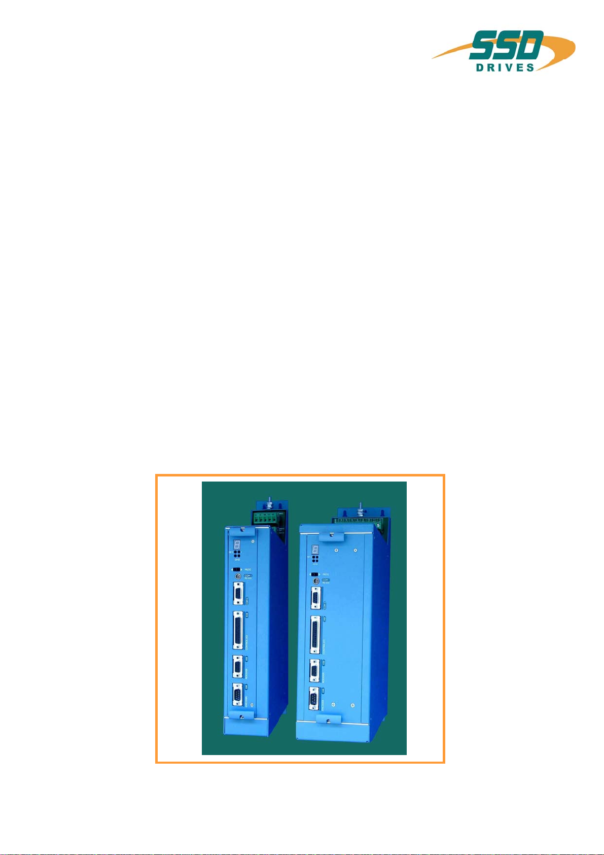
637
Servo drive
Product
Manual
________________________________________________________________________________________________________________________________________________________________________________________________________________________
2 Product Manual Type: 637 07-02-08-03-E-V1204.doc
Further descriptions, that relate to this document:
UL:07-02-01
Product - manual Rack 6 U and EMV
UL:07-02-02-01
Product - manual Power supply plug-in module NE B
UL:07-05-02-03
Product - manual SUCOnet K
UL:07-05-03-02
Product - manual Bus interface CAN for 635 637 637+
UL:07-05-04-02
Product - manual Bus interface DP for 635 637 637+
UL:07-05-05-02
Product - manual Bus interface Interbus S for 635 637 637+
UL:07-05-07-02
Product - manual I/O Interface for 635 637 637+
UL:07-05-08-02
Product - manual Bus interface DeviceNet for 635 637 637+
UL:07-09-04-02
Product - manual Supression aids EH
________________________________________________________________________________________________________________________________________________________________________________________________________________________
07-02-08-03-E-V1204.doc Product Manual Type: 637 3
Further descriptions, that relate to this document.
UL:10-06-03
Product - manual Serial transfer protocol 635 637 637+EASY-serial
UL: CD
EASYRIDER®Windows - Software
UL:10-06-05
Product - manual Software BIAS®
UL: 12-01
Product - manual Accessories - Plugs
UL:12-02
Product - manual Accessories - Cable
UL:12-03
Product - manual Accessories - Brake resistances
©SSD Drives GmbH.
All rights reserved. No portion of this description may be produced or processed in any form without the
consent of the company.
Changes are subject to change without notice.
SSD Drives has registered in part trademark protection and legal protection of designs.
The handing over of the descriptions may not be construed as the transfer of any rights.
Made in Germany, 2004

________________________________________________________________________________________________________________________________________________________________________________________________________________________
4 Product Manual Type: 637 07-02-08-03-E-V1204.doc
CONTENTS
page
The most important thing first ..........................................................................7
Safety precautions .............................................................................................8
1 General ....................................................................................................10
1.1 System description .......................................................................................................................10
1.1.1 Digital communication...................................................................................................................11
1.1.2 Operation configurations...............................................................................................................11
1.1.3 Compatibility to SSD Drives-6 U analog regulator FRR AC S......................................................12
1.2 Typecode......................................................................................................................................13
1.2.1 Example........................................................................................................................................13
1.3 Range data ...................................................................................................................................14
1.3.1 Insulation concept.........................................................................................................................14
1.3.2 General Datas...............................................................................................................................14
1.3.3 Compact units 637/K D6R............................................................................................................15
1.3.4 Plug-in modules 637/D6R.............................................................................................................16
1.3.5 Single- and three-phase supply....................................................................................................17
1.3.6 Output power ................................................................................................................................18
1.3.7 Rated current / max. current – period..........................................................................................18
1.4 Dimensions and layout .................................................................................................................19
1.4.1 Dimensions for compact device
and plug-in module.......................................................................................................................19
1.4.2 EMC-Clip (optional) .....................................................................................................................20
1.4.3 Layout...........................................................................................................................................21
2 Connector assignment and functions..................................................22
2.1 General view of connections of the compact device 637/K D6R 02...10 .....................................22
2.1.1 General view of connections of the compact device 637/K D6R 16...30 .....................................23
2.2 Signal connections........................................................................................................................24
2.2.1 Power connections for plug-in module 637/D6R..........................................................................24
2.3 Signal connections........................................................................................................................25
2.3.1 Control signal plug X10 SUB D25 socket.....................................................................................25
2.4 Resolver........................................................................................................................................28
2.4.1 Resolver connection X30 SUB D 09 socket.................................................................................28
2.5 Multi-function X40.........................................................................................................................29
2.5.1 Incremental output........................................................................................................................30
2.5.2 Incremental input..........................................................................................................................31
2.5.3 Stepper motor input......................................................................................................................32
2.5.4 Stepper motor input......................................................................................................................33
2.6 Digital interfaces ...........................................................................................................................34
2.6.1 Service interface COM1 (RS232).................................................................................................34
2.6.2 Fieldbus interface COM2..............................................................................................................35
3 Operating modes....................................................................................41
3.1 Operating modes and pin functions..............................................................................................42
3.2 Configurable pin-functions (depending on the operating mode)..................................................43
3.3 Function diagrams from inputs and outputs .................................................................................44

________________________________________________________________________________________________________________________________________________________________________________________________________________________
07-02-08-03-E-V1204.doc Product Manual Type: 637 5
CONTENTS
page
4 Mechanical installation ..........................................................................45
4.1 Mounting.......................................................................................................................................45
4.2 Control cabinet - mounting............................................................................................................45
4.3 Cooling..........................................................................................................................................45
5 Electrical installation..............................................................................46
5.1 Safety............................................................................................................................................46
5.2 The danger of electric shocks.......................................................................................................46
5.3 Danger areas................................................................................................................................46
5.4 Grounding, safety grounding ........................................................................................................46
5.4.1 Ground connections......................................................................................................................46
5.5 Short-circuit capability and discharge currents.............................................................................46
5.6 Fuses, contactors, filters...............................................................................................................47
5.7 Correction of supply current .........................................................................................................48
5.8 Brake resistor................................................................................................................................49
5.8.1 Selection of the brake resistor......................................................................................................49
5.8.2 Configuration of the brake resistor ...............................................................................................50
5.8.3 Additional informations .................................................................................................................51
6 Wiring instructions.................................................................................52
6.1 General Information......................................................................................................................52
6.2 Control cabling..............................................................................................................................52
6.3 Power cabling ...............................................................................................................................52
6.4 Installation of the rack...................................................................................................................52
6.5 Analog setpoint.............................................................................................................................52
6.6 Safety rules...................................................................................................................................52
6.7 Electromagnetic compatibility (EMC)............................................................................................52
6.7.1 Hints for mounting.........................................................................................................................53
6.7.2 Example for mounting...................................................................................................................54
6.7.3 Achieveable specifications and conditions...................................................................................55
7 Setting and programming......................................................................56
7.1 Jumper..........................................................................................................................................56
7.2 Digital communication...................................................................................................................56
7.3 PROG-key functions.....................................................................................................................57
7.3.1 Description for PROG-key............................................................................................................57
7.3.2 Operating via PROG-key..............................................................................................................58
8 Commissioning.......................................................................................59
8.1 Preparation ...................................................................................................................................59
8.2 Commissioning in steps................................................................................................................60
9 Diagnosis and trouble shooting............................................................63
9.1 7-segment display.........................................................................................................................63
9.2 Reset of a regulator trouble..........................................................................................................65
9.3 Trouble shooting...........................................................................................................................66

________________________________________________________________________________________________________________________________________________________________________________________________________________________
6 Product Manual Type: 637 07-02-08-03-E-V1204.doc
CONTENTS
page
10 Block circuit diagram.............................................................................67
11 General technical data ...........................................................................68
11.1 Power circuit .................................................................................................................................68
11.2 Control circuit................................................................................................................................68
11.3 Signal inputs and outputs, connection X10 ..................................................................................68
11.4 Digital control................................................................................................................................69
11.5 Digital communication...................................................................................................................69
11.6 Resolver evaluation/transmitter principle......................................................................................69
11.7 Controllersystem...........................................................................................................................69
11.8 Measuring sockets MP1 and MP2................................................................................................70
11.9 Thermal data.................................................................................................................................70
11.10 Mechanical data............................................................................................................................70
12 Disposal...................................................................................................70
13 Software...................................................................................................71
13.1 EASYRIDER®Windows - Software..............................................................................................71
13.2 SSD Drives programming language BIAS....................................................................................72
13.3 BIAS-commands...........................................................................................................................74
13.4 Extended BIAS-commands...........................................................................................................75
14 Certificates ..............................................................................................76
15 Index ........................................................................................................82
16 Modification Record...............................................................................84

________________________________________________________________________________________________________________________________________________________________________________________________________________________
07-02-08-03-E-V1204.doc Product Manual Type: 637 7
The most important thing first
Thanks for your confidence choosing our product.
These operating instructions present themselves as an overview of the technical data and
features.
Please read the operating instructions before operating the product.
If you have any questions, please contact your nearest SSD Drives representative.
Improper application of the product in combination with dangerous voltage can lead to
injuries.
In addition, damage can also occur to motors or other products.
Therefore please observe our safety precautions strictly.
Safety precautions
We assume that, as an expert, you are familiar with the relevant safety regulations,
especially in accordance with VDE 0100, VDE 0113,VDE 0160, EN 50178, the accident
prevention regulations of the employers liability insurance company and the DIN
regulations and that you are able to use and apply them.
As well, relevant European Directives must be observed.
Depending on the kind of application, additional regulations e.g. UL, DIN are subject to be
observed.
If our products are operated in connection with components from other manufacturers,
their operating instructions are also subject to be observed strictly.
________________________________________________________________________________________________________________________________________________________________________________________________________________________
8 Product Manual Type: 637 07-02-08-03-E-V1204.doc
Safety precautions
Attention!
The digital servo drives are in the sense of EN 50178/VDE 0160 power electronic equipments for
regulating the flow of energy in electrical power installations.
They are exclusively for supplying SSD Drives (or SSD Drives approved) servomotors.
Handling, installation, operation, and maintenance are only permitted under the conditions of and in
keeping with the effective and/or legal regulations, regulation publications and this technical document.
The operator must make sure that these regulations are strictly followed.
Concept of the galvanic separation and insulation:
Galvanically separation and insulation correspond to EN 50178/VDE 0160, amplified insulation.
In addition all digital signal inputs and outputs are galvanically separated either as a relay or via opto
coupler. In this way an increased interference security and the limitation of damages in case of external
incorrect connections is given.
The voltage level must not exceed the low safety voltage 60V DC or 25V AC, respectively in accordance
with EN 50178/VDE 0160.
The operator must make sure that these regulations are strictly followed.
Danger !
High contact voltage !
Danger of getting shocked !
Danger to your life !
Caution!
Opening the servo drive by the operator is prohibited due to reasons of safety and guarantee. The
requirement for problem-free operation of the servo drive is the expert configuring !

________________________________________________________________________________________________________________________________________________________________________________________________________________________
07-02-08-03-E-V1204.doc Product Manual Type: 637 9
Safety precautions
Please observe !
Especially to be complied with:
The class of protection which is permitted: protective grounding; operation is only permitted when the
protective conductor is connected according to regulations.
The operation of servo drives is not allowed under the sole use of a residual current operated protective
device as protection against indirect touching.
The servo drive may only be used in the rack or in its compact enclousure. Furthermore the regulator is
designed solely for control cabinet operation.
Work on or with the servo drive may only be carried out with insulated tools.
Installation work may only be done in a deenergized state. When working on the drive, do not only block the
Active-input but separate the complete drive from the mains.
CAUTION - risk of electrical shock, wait 3 minutes after switching off, for discharging the capacitors.
Screws sealed with varnish fulfill an important protection function and may not be moved or removed.
It is prohibited to penetrate the inside of the unit with objects of any kind.
Protect the unit from falling parts (pieces of wire, fley, metal parts, etc.) during installation or other work in
the control cabinet. Metal parts can lead to a short in the servo drive.
Before putting into operation, remove additional covers so that the unit does not overheat. With
measurements at the servo drive it is absolutely necessary to observe the potential separation!
Stop !
SSD Drives GmbH is not liable for damages whith occur by not following the instructions
or the applicable regulations !!
________________________________________________________________________________________________________________________________________________________________________________________________________________________
10 Product Manual Type: 637 07-02-08-03-E-V1204.doc
1 General
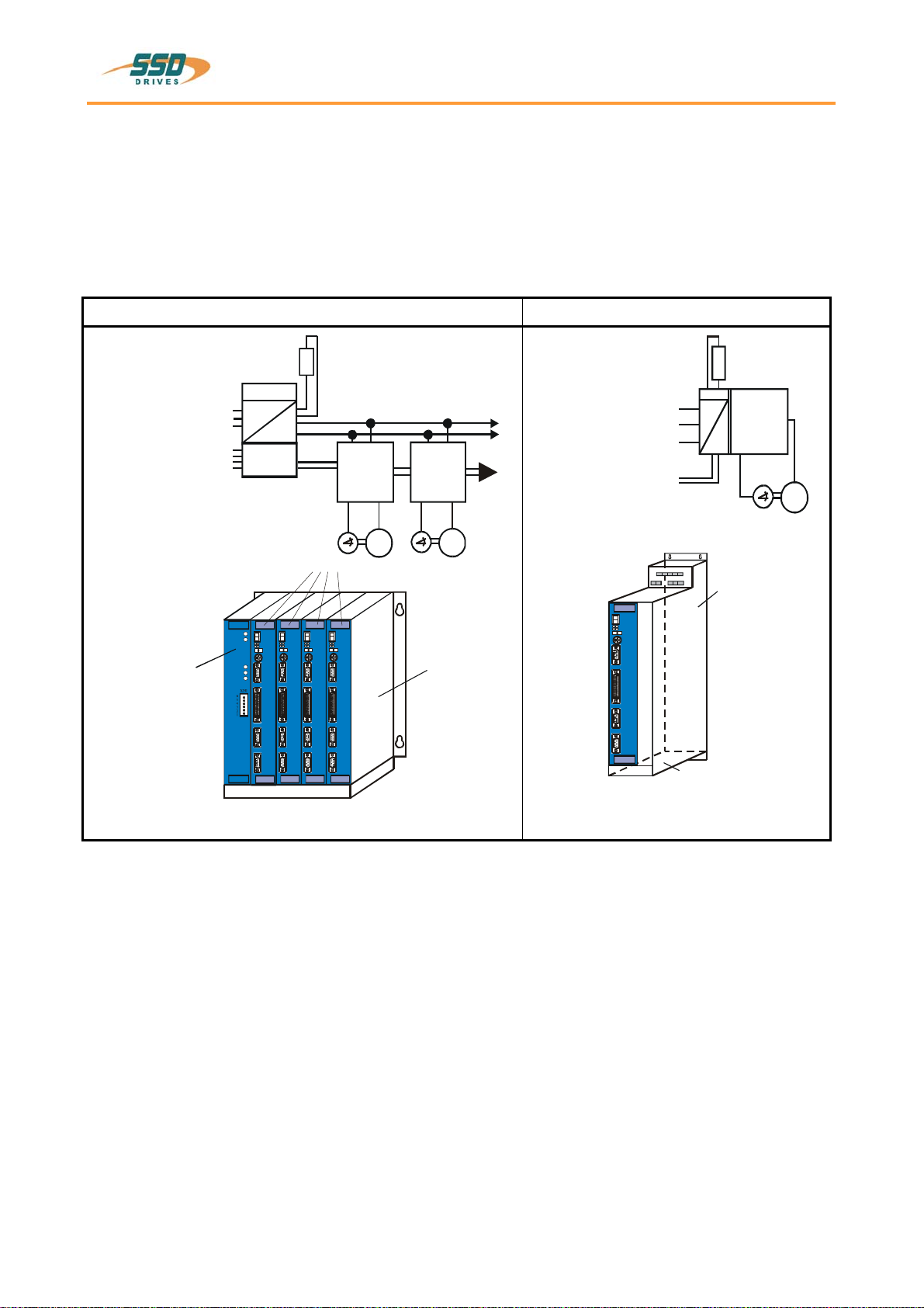
1.1 System description
The digital servo drive serves the 3rd generation to regulate the current, speed and position of
AC servo motors,(standard: with resolver)
All servo controls and functions are realized digitally.
System variants
Rack-version: 637/D6R.... Compact-version: 637/K D6R....
Us 24V DC
AC
DC
NEB...
optional
DC-BUS
Ucc
R
24V DC
M
637/D6R
M
637/D6R
Supply voltage:
1*or 3*230VAC/50..60Hz
3* 400... 460VAC/50..60Hz
637/K D6R
AC
DC
Us 24VDC
R
Supply voltage:
1*or 3*230VAC/50..60Hz
3*400...460VAC/50..60Hz
M
Explanations to rack and power supply modules are documented in separate description.
If required, the returned braking energy can be drawn off into additional external ballast resistors.
The AC-supply voltage is fed directly or via transformer to the associated power supply module.
The devices are designed to be operated on networks which are grounded on
centre point (TN networks) !
Fan
Power supply
plug-in module
NE B
Rack, R6
or
R6 EMC
Servodrives
Fan
Servo-
drive
Power supply unit
________________________________________________________________________________________________________________________________________________________________________________________________________________________
07-02-08-03-E-V1204.doc Product Manual Type: 637 11
System description
1.1.1 Digital communication
Diagnose / Setup
General: by 7-segment display
Comfortable: via PC by EASYRIDER®Windows - Software
(serial interface RS232)
Communication
The serial-communication-protocol is free documented.
(Explanation see seperate documentation)
Every user has unrestricted acces to all functions and parameters.
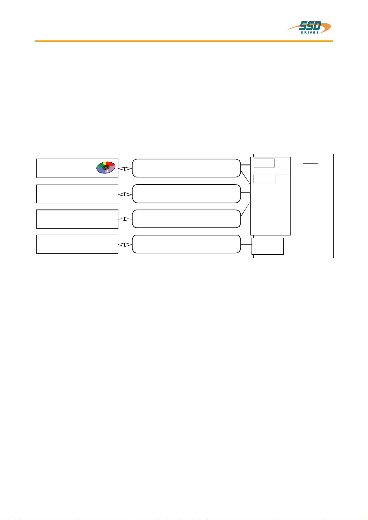
1.1.2 Operation configurations
There are opportunities ranging from simple current and speed control to programmable position control
processes (PLC), supported by the 1500 BIAS- command blocks.
"BIAS" User shell for intelligent drive controls
see:
chapter 3 Operating modes
chapter 13.2 BIAS - commands
chapter 13.3 Extended BIAS – commands
EASYRIDER
custom-made software
PLC Software
PLC, binary selectionl,+/- 10V
X10
RS232,
RS422,
RS485,
CAN
-
Bus,
Profibus DP,
current-loop
speed-loop
p
osition-loop
instructions
⌧
programming
diagnostics
setup
⌧
⌧
SPS
SUCOnet K,
Interbus S
COM1
COM2
⌧
RS232,
DeviceNet
637

________________________________________________________________________________________________________________________________________________________________________________________________________________________
12 Product Manual Type: 637 07-02-08-03-E-V1204.doc
System description
1.1.3 Compatibility to SSD Drives-6 U analog regulator FRR AC S
(Not required for new projects)
The digital servo drives are to a great extent pin- and function compatible to the analog devices of the FRR
AC S series.
The EASYRIDER®Windows - Software allows the adaption to your existing equipment.
(see: chapter 3 Operating modes)
Further adaptions can be done by solder-jumpers (see: chapter 7.1 Jumper)
Compatibility restrictions:
Restriction
1 External current limiting
due to analog input at X10.19
In the PC configuration menu the function speed regulator parameter (freely scaled) can be activated.
In few cases the internal Pull-Up resistor with FRR AC S was loaded with an external Pull-Down
resistor in order to reach a current limiting. The Pull-Up resistor on the D6R+K D6R can be activated
via the solder strip JP101.
2 Incremental encoder output-zero offset
With FRR AC S a zero drift was possible by means of DIP switch. This function is not realized with
637/D6R+K D6R.
3 Temperature monitoring output T2
(only with FRR AC S with corresponding option circuit) T2 is no more signalized.
4Reference potential
all digital in- and output signals on X10 are referred to X10.9.
5 Temperature monitoring PTC
(only with FRR AC S with corresponding option circuit)
Before switching off for approx 3 seconds "WARNING" is signalized.
6Reset
Connector X10.2 is no more assigned with reset function.
7n/I-Switch over
Connector X10.11 is not reference potential for n/I-switch over anymore, but X10.9.
8Warning
Connector X10.7 is not reference potential for warning output anymore, but X10.9.
9The max. operating voltage on all signal outputs of X10 is DC 45V DC.
10 Pin 26 on X50 is not assigned internally and must be free !
One cannot completely rule out the possibility that with special designs of FRR AC S devices additional
adjustments have to be made.

________________________________________________________________________________________________________________________________________________________________________________________________________________________
07-02-08-03-E-V1204.doc Product Manual Type: 637 13
1.2 Typecode
Standard optional
Marking a b c d e f g
Typ: XXX/ X D6R XX .S3 -X -X -XXX
Marking Description
XXX/ = 637 ≅SSD Drives- design (blue)
a K = 1 axis compactdigital servo drive system
= (is not used with model plug-in device)
b D6R = Digital 6U Regulator
c Rated current:
02 = 2 amperes
04 = 4 amperes
06 = 6 amperes
10 = 10 amperes
16 = 16 amperes
22 = 22 amperes
30 = 30 amperes
d .S3 = Digital drive 3 th generation
e Intermediate circuit rated voltage:
-3 = 325V (230V AC) 16..30A only as for rack version possibly
-7 = 650V (460V AC)
f -E = with EMC-Clip
-0 = without EMC-Clip
additional optionmodules on the drive for communication via COM2
-232 = RS 232 interface
-422 = RS 422 interface
-485 = RS 485 interface
-CAN = CAN - bus
-DEV = CAN - bus / DeviceNet
-SUC = SUCOnet K
-PDP = Profibus DP
-IBS = Interbus S (Attention: changed front plate)
–EA5 = I/O - interface (5E, 2A) COM2
g
–EAE = I/O - Interface (14E, 10A) X200 (Attention: changed front plate)
–XXE = Combination of communication interface
and I/O interface EAE (the first two places of com.-interface + E for
I/O-interface EAE)
1.2.1 Example
Typical example of an order of a 1-axis- compact device in SSD Drives-design
Type: 637/K D6R 02.S3-7-CAN
637/ = SSD Drives-design (blue)
K = 1 axis compact device
D6R = Digital 6U Regulator
02 = 2amperes Regulator rated current
.S3 = Digital drive 3th generation
-7 = 650V UCCN
-CAN = CAN- bus – Optionsmodule insertion
________________________________________________________________________________________________________________________________________________________________________________________________________________________
14 Product Manual Type: 637 07-02-08-03-E-V1204.doc
1.3 Range data
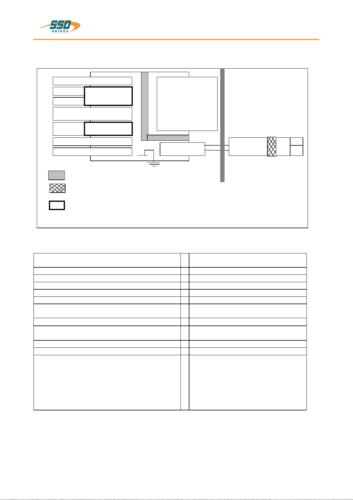
1.3.1 Insulation concept
COM1
COM2
Remote IN
X10
analog
X10
digital
X40
X30
dep.Optionsmodule
M1, M2, M3
DC-bus
brak - cirquit
L1,L2,L3
Us DC 24 V powersupply
DC 24 V
PE
L1
N
AC
power - terminals
double insulation VDE 0160
Insulation ofcontrol voltage supply
Required for safeseparation (PELV):double insulation
Take Care !The insulation ofcontrol (Com1..X40)depends on the insulation ofcontrol voltagesupply
Additional insulation via opto-coupler or relay(withoutSafety-Functions)
customer part
1)
1) see additional hints, chapter 2.4.2
GND
1.3.2 General Datas
Enclosure Rating
(for mounting in cubicle) IP20
operating temperature range EN 50178 / VDE 0160, Klasse 3K3
storage temperature range -25°...+55° C
air pressure 86 kPa - 106 kPa
Humidity 5 % - 85% 40°C
Opertating Temp 0...40°C
reduced operation
derating of the output current
1) >40°...< 50°C
2% /°C
Altitude h h ≤1000m
reduced operation
Derating of the output current
1) h > 1000...≤4000m
1% / 100m
Safety Overvoltage-category of power circuit EN 50178 / VDE 0160, UL, cUL III,
Pollution degree for mounting in cubicle VDE / UL: 2
Vibration test in accordance with
DIN IEC 68-2-6, test FC
Condition for testing
Frequency range
Amplitude
Acceleration
Test time per axis
Frequency sweep speed
10...57Hz 57...150Hz
0,075 mm
1g
10 Frequenzzyklen
1 Oktave/min
1) Use only fan-cooled devices. For reduced operating
conditions, no UL-Approbation are available.

________________________________________________________________________________________________________________________________________________________________________________________________________________________
07-02-08-03-E-V1204.doc Product Manual Type: 637 15
Range data
1.3.3 Compact units 637/K D6R
Compact units 637 / K D6R 02
.S3 K D6R 04
.S3 K D6R 06
.S3 K D6R 10
.S3 K D6R 16
.S3 K D6R 22
.S3 K D6R 30
.S3
-3 -7 -3 -7 -3 -7 -3 -7 -7 -7 -7
Input
supply voltage min. [V] 14
50..60 Hz Un [V] 230 460 230 460 230 460 230 460 460 460 460
max. tolaranc
e + 10%
phases 1;3 3 1;3 3 1;3 3
supply-preparation Fuses, contactors, filters see chapter 5.6
power-on current
limit
Type NTC 4 Ohm NTC 2 Ohm
control voltage 1) Us [V] 21,5....24....29, attention: insulation-concept chapter 1.3.1
control current
incl. Fan
Is
DC [A] Continuous: max. 1,2A
Power-On-Peak:
nom. 3A; max.. 6A / 0,8 mS, 2,5A / 25 mS
Continuous: max 1,5A
Power-On-Peak: nom. 3A;
max. 6A / 0,8 mS, 3A / 25 mS
Output
sine-wave volt. At Un Unr [Veff] 220 447 220 447 220 447 220 447 447 447 447
3)
derating of Unr depending on load and single or 3-phase supply. (see chapter 1.3.5)
rated current RMS Inr [A] 2 4 6 10 16 22 30
3)
max. current RMS
time for Imax
4) Imaxr
min. [A]
Sec 4
5 8
5 12
5 20
5 32
5 44
5 60
5
min. motor
inductance
(terminal / terminal)
Lph/ph [mH] 6,0 12,0 3,0 6,0 2,0 4,0 1,2 2,4 2,0 1,1 0,8
Brake circuit
Setpoint DC Ub [V] 375 730 375 730 375 730 375 730 730 730 730
max. power Pbmax [kW] 4,5 8,7 4,5 8,7 6,7 13,0 11,2 21,7 29,0 34,8 34,8
continuous power Pbnenn [W] ≤560
internal resistor Rbint
Pd
Pmax
[Ω]
[W]
[kW]
100
30
1,4
300
30
1,7
100
30
1,4
300
30
1,7
100
30
1,4
300
30
1,7
100
30
1,4
300
30
1,7
------
min. external resistor 2) Rbextmi
n [Ω] 47 82 47 82 27 47 15 27 20 15 15
General
power loss
fan, electronic
PE loss
[W]
29
29
29
29
29
29
29
29
36
36
36
2 Piece L 024 / (16TE x 25)fan models
24V DC [V] 2 Piece L 024 / (12TE * 25)
1 Piece L 024 / (12TE * 15) 1 2 Piece L 024 /
(16TE x 20)
power stage per A [W/A] 9 12 9 12 9 12 9 12 12 12 12
weight [kg] 5,0 8,8
further data see: chapter 11
1) suggested: transformer-based supply
2) use only SSD Drives-released types
3) max. continuous performance derated to 80%, see chapter 1.3.6
4) References chapter 1.3.6

________________________________________________________________________________________________________________________________________________________________________________________________________________________
16 Product Manual Type: 637 07-02-08-03-E-V1204.doc
Range data
1.3.4 Plug-in modules 637/D6R
Plug-in modules
637/ D6R 02
.S3 D6R 04
.S3 D6R 06
.S3 D6R 10
.S3 D6R 16
.S3 D6R 22
.S3 D6R 30
.S3
-3 -7 -3 -7 -3 -7 -3 -7 -3 -7 -3 -7 -3 -7
Input
DC-BUS rated min. [V] 20
Ug [V] 325 650 325 650 325 650 325 650 325 650 325 650 325 650
max.
o
eranc
e
+ 10%
control voltage Us [V] 24V DC +20% -10%, attention: insulation-concept chapter 1.3.1
control current 1) Is
DC [A]
Continuous: max 0,8A Power-On-Peak: nom. 2A; max 5A / 0,8 mS, 2A / 25mS
Fan
2) Typ
--- L220
K --- L220K L220G
Output
sine-wave volt.
at Un Unr [Veff] 220 447 220 447 220 447 220 447 220 447 220 447 220 447
3)
derating of Unr depending on load and single or 3-phase supply (see chapter 1.3.5)
rated current RMS Inr [A] 2 4 6 10 16 22 30 3)
max. current RMS
time for Imax Imaxr [A]
min. 4
5 Sec 8
5 Sec 12
5 Sec 20
5 Sec 32
5 Sec 44
5 Sec 60
5 Sec
min. motor
inductance
(terminal / terminal)
Lph/ph [mH] 6,0 12,0 3,0 6,0 2,0 4,0 1,2 2,4 1,0 2,0 0,55 1,1 0,4 0,8
Brake-Circuit
setpoint DC Ub [V] 375 730 375 730 375 730 375 730 375 730 375 730 375 730
max. power Pbmax [kW] 4,5 8,7 4,5 8,7 6,7 13,0 11,2 21,7 15,0 29,0 18,0 34,8 18,0 34,8
continuous rating Pbnenn [W] ≤560
min. external
resistor
2) Rbextmi
n [Ω] 33 63 33 63 22 43 12 24 10 20 8,2 15 8,2 15
General
power loss
electronic
output stage per A
PEloos
[W]
[W/A]
20
9
20
12
20
9
20
12
20
9
20
12
20
9
20
12
20
9
20
12
20
9
20
12
20
9
20
12
weight [kg] 1,5 4,0
further data see chapter 11
1) suggested: transformer-based supply
2) use only SSD Drives-released types
3) max. continuous performance derated to 80%, see chapter 1.3.6
4) References chapter 1.3.6
________________________________________________________________________________________________________________________________________________________________________________________________________________________
07-02-08-03-E-V1204.doc Product Manual Type: 637 17
Range data
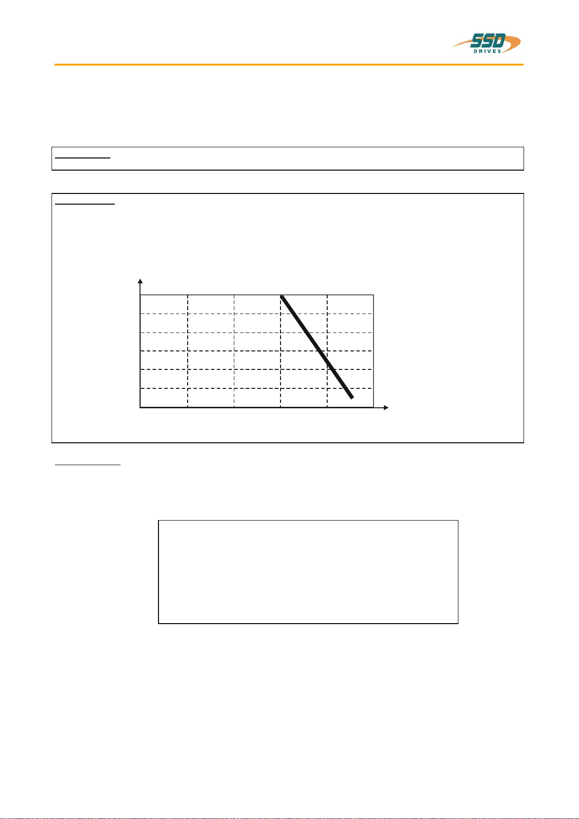
1.3.5 Single- and three-phase supply
Due to the line-ripple of DC-Bus, the rate of usable output voltage is derated like follows.
This deration effects the max. reachable speed of the applied motor.
Three-phase-supply:
the unloaded output voltage will be derated to approx. 90%, maximum 85 %
Single-phase: supply: 50 – 60Hz
only drive 637 / ..02 up to 06
see following diagram:
Hints for setup:
To avoid unexpected tripping of undervoltage threshold
(EASYRIDER®Windows - Software), this value should be set to default.
Required motor-terminal-voltage forspecified speed.
Approximation: (up to 3000RPM)
Ukl = 1,2 * (EMF * n / 1000) + I * (Rph + RL) [V]
Ukl required motorvoltage [V RMS]
EMF Back-EMF of motor [V RMS] / 1000 RPM
Rph resistance of motor (between terminals) [Ω]
RL line resistance of motor cable [Ω]
I motor-current [A RMS]
Output current [Aeff]
Derating of servo drive output voltage in case of single-phase supply
2
4
6
8
10
20 40 60 80 100
0 0
12
[%]
Output voltage in % of unloaded condition
________________________________________________________________________________________________________________________________________________________________________________________________________________________
18 Product Manual Type: 637 07-02-08-03-E-V1204.doc
Range data
1.3.6 Output power
In case of continuous operation in the range of full-load the limits like shown in the diagram have to be
respected.
Typical servo applications are not effected by this restriction. (S3-operation: Start/Stop)
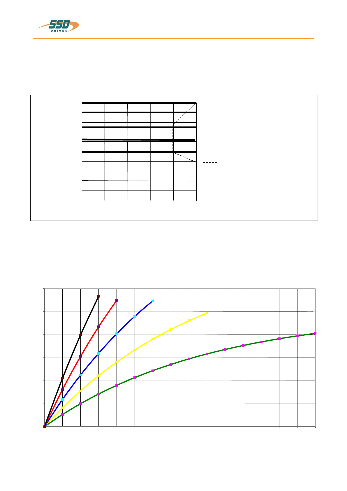
1.3.7 Rated current / max. current – period
0,2
0,4
0,6
0,8
1,0
20 40 60 80 100
00
1,2
[%]
1,4
1,6
1,8
2,0 5 sec
10 sec
20 sec
Imaxr / Inr 6,25 sec Duration of pulse
until supervising reaction
Cont. operation
Derating ONLY for
xD6R30.S3-x
Output voltage [%]
Guaranteed minimum requirements value I2T- work load
Series 631/5/7
0,00
20,00
40,00
60,00
80,00
100,00
120,00
0 2 4 6 8 10 12 14 16 18 20 22 24 26 28 30
time [sec]
work load[%]
Imax/Inenn=2Imax/Inenn=1,75 Imax/Inenn=1,5
Imax/Inenn=1,25
Imax/Inenn=1

________________________________________________________________________________________________________________________________________________________________________________________________________________________
07-02-08-03-E-V1204.doc Product Manual Type: 637 19
1.4 Dimensions and layout
1.4.1 Dimensions for compact device
and plug-in module
637/K D6R 02...10 width 637/K D6R 16...30 width
A 65,0 mm 14 HP 104,6 mm 20 HP
B 60,0 mm 100,0 mm
C 30,0 mm 71,0 mm 1 HP ≈5,08mm
D 14,5 mm 14,5 mm
a 40,2 mm 8 HP 80,4 mm 16 HP
Important:
Make sure you need an additional space of approx. 70 mm on the front side for the signal mating
plugs !
A
B
C
DD
400
386
262
a
280
233 304
243
220
p
lug-in module
space for fan
18
Ø 5,2
Ø 10
Ø 5,2
5,2
9
detail
detail
E
E1,6
front side

________________________________________________________________________________________________________________________________________________________________________________________________________________________
20 Product Manual Type: 637 07-02-08-03-E-V1204.doc
Dimensions and layout
1.4.2 EMC-Clip (optional)
1.4.2.1 for 8 HP drive
side view front view
1.4.2.2 for 16 HP drive
side view front view
EMC-Clip for
Feedback- cable
(e.g. Resolver) 1
net cable 2
Motor cable 3
meaning:
1,2,3 = cage clamp terminal
Table of contents
Other SSD Drives Servo Drive manuals


Popular Servo Drive manuals by other brands


REXROTH
REXROTH EcoDrive Cs Project planning manual

Harmonic Drive
Harmonic Drive HA-675 Series manual

Elmo
Elmo Gold DC Whistle Series installation guide

DF ROBOT
DF ROBOT Veyron manual

Electro-Craft
Electro-Craft BRU-200 instruction manual

Rockwell Automation
Rockwell Automation Allen-Bradley Kinetix 5300 installation instructions