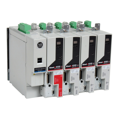
Smitec Cosmos Series User manual

Smitec S.p.A., viale Vittorio Veneto 4, 24016 San Pellegrino Terme (BG), Ital , www.smitec.it
Installation, use and maintenance manual
BEFORE STARTING THE COSMOS 315 /325 /350 SERIES SERVO DRIVE,
CAREFULLY READ THIS MANUAL AND FOLLOW ALL INSTRUCTIONS, IN
ORDER TO ENSURE MA IMUM SAFETY
SERVODRIVES
COSMOS SERIES 315 /325 /350
The technical data and the drawings in this manual might have been modified later; always refer to
the latest version.

COSMOS DRIVER SERIES 3000 - USE AND MAINTENANCE MANUAL
CONTENTS
1 PREFACE ......................................................................................................................... 6
2 GENERAL WARNINGS ..................................................................................................... 7
3 SAFETY INSTRUCTIONS ................................................................................................. 9
3.1 GENERAL INFORMATION ...................................................................................................................... 9
3.2 PRECAUTIONS DURING HANDLING AND ASSEMBLY ......................................................................................... 9
3.3 PRECAUTIONS AGAINST RISK OF ELECTRIC SHOCK ..................................................................................... 10
3.4 PRECAUTIONS AGAINST HOT COMPONENTS .............................................................................................. 11
4 PRODUCT FEATURES ................................................................................................... 12
4.1 DESCRIPTION ............................................................................................................................... 12
4.2 DRIVER MODELS ............................................................................................................................ 13
4.2.1 Or er co es ........................................................................................................................ 14
4.2.2 Mo el co e ........................................................................................................................ 16
4.2.3 Accessories ........................................................................................................................ 17
4.3 RATINGS .................................................................................................................................... 18
4.4 THERMAL DISSIPATION .................................................................................................................... 19
4.5 AMBIENT SPECIFICATIONS ................................................................................................................. 21
4.6 ELECTROMAGNETIC COMPATIBILITY (EMC) ............................................................................................ 21
4.7 PHYSICAL SPECIFICATIONS ................................................................................................................ 22
4.7.1 Weight ............................................................................................................................... 22
4.7.2 Size of COSMOS Type 315X / 325X ....................................................................................... 22
4.7.3 Size of COSMOS Type 3500/1 (first series) ............................................................................ 23
4.7.4 Size of COSMOS Type 3500/1 (secon series) ....................................................................... 24
4.7.5 Size of COSMOS Type 3502 ................................................................................................. 25
5 INSTALLATION ............................................................................................................ 26
5.1 POSITIONING AND INSTALLATION ........................................................................................................ 26
5.1.1 COSMOS Type 315X/325X ................................................................................................... 26
5.1.2 COSMOS Type 3500/1 (first series) ...................................................................................... 27
5.1.3 COSMOS Type 3500/1 (secon series) ................................................................................. 28
5.1.4 COSMOS Type 3502 ............................................................................................................ 29
5.2 ELECTRICAL INSTALLATION ................................................................................................................ 30
5.2.1 Power installation ............................................................................................................... 30
5.2.2 Signal installation ................................................................................................................ 31
5.2.3 Earth wiring ....................................................................................................................... 32
5.3 CONNECTORS WIRING ..................................................................................................................... 33
5.3.1 Auxiliary power supply input (24VDC/J5 ) ............................................................................. 33
5.3.2 Main power supply input (LINE/J1) ...................................................................................... 34
5.3.3 Motor output (MOTOR/J4) ................................................................................................... 36
5.3.4 DC BUS power supply (DC BUS/J3) ...................................................................................... 37
5.3.5 Dynamic brake output (BRAKE R/J2) .................................................................................... 38
5.3.6 Enco er 1 input (E1) ........................................................................................................... 39
5.3.6.1 COSMOS Type 3XXX (first series) .................................................................................................. 39
5.3.6.2 COSMOS Type 3XXX (secon series) ............................................................................................. 40
5.3.7 Enco er input/output 2 (E2) ................................................................................................ 42
Ver. 1.07 Pag. 2

COSMOS DRIVER SERIES 3000 - USE AND MAINTENANCE MANUAL
5.3.7.1 Enco er input .............................................................................................................................. 42
5.3.7.2 Enco er repetition output ............................................................................................................. 43
5.3.8 STO system I/O (STO) ........................................................................................................ 44
5.3.9 General I/O ........................................................................................................................ 45
5.3.10 Fiel Bus FLxIO/Sercos III/Mo bus TCP (F1, F2) ................................................................. 46
5.3.10.1 FLxIO connection ...................................................................................................................... 46
5.3.10.2 SERCOS III/Mo bus TCP connection ........................................................................................... 46
5.3.11 Fiel bus Sercos II (FRX, FTX) ........................................................................................... 47
5.3.12 Operator interface (HMI) ................................................................................................... 47
5.3.13 USB (USB) ........................................................................................................................ 47
5.4 WIRING DIAGRAM .......................................................................................................................... 48
5.5 CHOICE OF THE WIRES AND FUSES ...................................................................................................... 49
5.5.1 Protection for use exclusively in compliance with IEC 61800-5-1 ............................................. 49
5.5.2 Protection for UL applications accor ing to IEC/UL 61800-5-1 an C22.2 No.274 ..................... 50
5.6 INSTALLATION CRITERIA FOR UL CERTIFICATION ...................................................................................... 51
6 SAFETY INTEGRATED SYSTEM .................................................................................... 52
6.1 DESCRIPTION ............................................................................................................................... 52
6.2 OPERATION ................................................................................................................................. 52
6.2.1 Signals ............................................................................................................................... 52
6.2.2 Electrical specifications ........................................................................................................ 52
6.2.3 System status ..................................................................................................................... 53
6.2.4 Intervention times .............................................................................................................. 53
7 OPERATOR INTERFACE ................................................................................................ 54
7.1 FUNCTION OF THE KEYS ................................................................................................................... 54
7.2 INTERACTION ............................................................................................................................... 55
7.2.1 Status message .................................................................................................................. 55
7.2.1.1 Controller Sercos III ..................................................................................................................... 55
7.2.1.2 Controller FLxIO .......................................................................................................................... 56
7.2.1.3 Controller Sercos II ...................................................................................................................... 56
7.2.1.4 Analogue controller ...................................................................................................................... 56
7.2.1.5 Service controller ......................................................................................................................... 56
7.2.1.6 Mo bus TCP/IP controller ............................................................................................................. 56
7.2.2 Access level ........................................................................................................................ 56
7.2.3 Main menu ......................................................................................................................... 57
7.2.4 Measure menu .................................................................................................................... 58
7.2.4.1 Mo els for brushless motor .......................................................................................................... 58
7.2.4.2 Mo els for asynchronous motor .................................................................................................... 59
7.2.4.3 Sercos II Cosmos ......................................................................................................................... 60
7.2.5 Status menu ....................................................................................................................... 61
7.2.5.1 Mo els for brushless motor .......................................................................................................... 61
7.2.5.2 Sercos II Cosmos ......................................................................................................................... 61
7.2.6 Control menu ...................................................................................................................... 62
7.2.6.1 Mo els for brushless motor .......................................................................................................... 62
7.2.6.2 Mo els for asynchronous motor .................................................................................................... 65
7.2.6.3 Sercos II Cosmos ......................................................................................................................... 67
7.2.7 Motor menu ........................................................................................................................ 69
7.2.7.1 Mo els for brushless motor an Sercos II version .......................................................................... 69
7.2.7.2 Mo els for asynchronous motor .................................................................................................... 71
7.2.8 Sercos menu ...................................................................................................................... 72
7.2.8.1 SERCOS™ stan ar features (CEI IEC 1491) ................................................................................. 72
7.2.8.2 SERCOS interface configuration .................................................................................................... 72
7.2.8.3 SERCOS interface status .............................................................................................................. 72
7.2.9 Analogue menu .................................................................................................................. 72
7.2.9.1 Analog controller ......................................................................................................................... 73
7.2.9.2 Analogue controller configuration ................................................................................................. 73
7.2.9.3 Analogue controller status ............................................................................................................ 74
Ver. 1.07 Pag. 3

COSMOS DRIVER SERIES 3000 - USE AND MAINTENANCE MANUAL
7.2.10 Service menu .................................................................................................................... 75
7.2.10.1 Mo els for brushless motor an for Sercos II Cosmos .................................................................. 75
7.2.10.2 Mo els for asynchronous motor ................................................................................................... 75
7.2.11 External brake menu ......................................................................................................... 76
7.2.11.1 Mo els for brushless motor an for Sercos II Cosmos .................................................................. 76
7.2.11.2 Mo els for asynchronous motor .................................................................................................. 76
7.2.12 Input/output menu ............................................................................................................ 78
7.2.13 Driver menu ....................................................................................................................... 81
7.2.13.1 Mo els for brushless motor ......................................................................................................... 81
7.2.13.2 Mo els for asynchronous motor .................................................................................................. 82
7.2.13.3 Sercos II Cosmos ....................................................................................................................... 82
7.2.14 Ethernet menu .................................................................................................................. 83
7.2.15 Enco er menu .................................................................................................................. 84
7.2.16 VISIO menu ...................................................................................................................... 85
7.2.16.1 Mo els for brushless motor ........................................................................................................ 85
7.2.16.2 Mo els for asynchronous motor .................................................................................................. 85
7.2.16.3 Sercos II Cosmos ....................................................................................................................... 85
8 LEDS AND ADDRESS (FLXIO SERCOS III AND MODBUS TCP) ................................... 86
8.1 ADDRESS SETTING ......................................................................................................................... 86
8.2 LEDS “LINE” AND “24VDC” .......................................................................................................... 87
8.3 LEDS “FLT” AND “STS” ............................................................................................................... 87
8.4 LEDS I1, I2 AND TO .................................................................................................................... 87
8.5 LEDS A AND L ............................................................................................................................ 87
8.6 LEDS FBS ................................................................................................................................. 88
8.6.1 Fiel bus FLxIO .................................................................................................................. 88
8.6.2 Fiel bus Sercos III ............................................................................................................. 88
9 LEDS AND ADDRESS (SERCOS II MODEL) ................................................................... 89
9.1 ADDRESS SETTING ......................................................................................................................... 89
9.2 P, E, O LEDS ............................................................................................................................. 89
9.3 FBS LEDS ................................................................................................................................. 89
9.4 FLT LED ................................................................................................................................... 89
9.5 D LED ...................................................................................................................................... 89
10 ERROR CODES (FLXIO SERCOS III AND MODBUS TCP) .......................................... 90
10.1 INTERNAL ERRORS ....................................................................................................................... 90
10.2 CONTROL ERRORS ........................................................................................................................ 91
10.2.1 Mo els for brushless motor ............................................................................................... 91
10.2.2 Mo els for asynchronous motor ......................................................................................... 93
10.3 WARNINGS ................................................................................................................................ 94
10.3.1 Mo els for brushless motor ............................................................................................... 94
10.3.2 Mo els for asynchronous motor ......................................................................................... 94
11 ERROR CODES (SERCOS II MODEL) .......................................................................... 95
11.1 DRIVER ERRORS .......................................................................................................................... 95
11.2 SERCOS ERRORS .......................................................................................................................... 97
11.2.1 Error co es ....................................................................................................................... 97
11.2.2 Solution of communication problems .................................................................................. 97
11.2.2.1 Errors from 21 to 25 .................................................................................................................. 98
11.2.2.2 Errors from 28 to 30 .................................................................................................................. 98
11.2.2.3 Error 32 .................................................................................................................................... 98
Ver. 1.07 Pag. 4

COSMOS DRIVER SERIES 3000 - USE AND MAINTENANCE MANUAL
11.2.2.4 Examples of errors ..................................................................................................................... 98
12 FIRMWARE UPDATE ................................................................................................ 100
12.1 UPDATE ON PC VIA USB CONNECTION ............................................................................................. 100
13 MAINTENANCE ......................................................................................................... 105
13.1 REPLACEMENT OF FAN BLOWER ........................................................................................................ 105
13.1.1 COSMOS Type 315X/325X ................................................................................................. 105
13.1.2 COSMOS Type 350X ........................................................................................................ 106
13.2 REPLACEMENT OF DYNAMIC BRAKE RESISTOR ........................................................................................ 106
13.2.1 COSMOS Type 325X ......................................................................................................... 106
Ver. 1.07 Pag. 5

COSMOS DRIVER SERIES 3000 - USE AND MAINTENANCE MANUAL
1 PREFACE
This manual is inten e to provi e the information necessary for the installation, use an maintenance of the COSMOS
315X/325X/350X series servo rives.
The instructions containe in this manual are inten e for the following professionals:
User User is a person, a company or an institution that buys the equipment and uses it for the
purposes it was designed for.
User/operator User or operator is a person authorized by the user to operate on the equipment.
Specialized personnel It refers to all persons with specific competence, able to recognize and avoid the dangers
deriving from the use of the equipment.
The present instructions must be ma e available to all the above in ivi uals.
Ver. 1.07 Pag. 6

COSMOS DRIVER SERIES 3000 - USE AND MAINTENANCE MANUAL
2 GENERAL WARNINGS
These assembly instructions are an integral part of the equipment, an must be kept for future reference until
ecommissioning.
The user shoul be informe that the present instructions reflect the state of the art at the moment when the equipment
was sol ; they will remain fully acceptable espite subsequent upgra es base on new experiences.
DO NOT USE THE EQUIPMENT, NOR MAKE ANY INTERVENTION BEFORE INTEGRALLY
READING AND UNDERSTANDING THIS MANUAL.
IN PARTICULAR, ADOPT ALL SAFETY PRECAUTIONS AND PRESCRIPTIONS INDICATED IN THIS MANUAL.
THE EQUIPMENT CANNOT BE USED FOR PURPOSES DIFFERENT THAN THE ONES DESCRIBED IN THIS
MANUAL; SMITEC S.p.A. SHALL NOT BE HELD RESPONSIBLE FOR ANY DAMAGES, INCONVENIENCES OR
ACCIDENTS DUE TO THE NON-COMPLIANCE WITH THESE PRESCRIPTIONS.
In or er to make the manual consultation easier, the following symbols have been a opte :
Indication of “ ROHIBITED ACTION”.
The symbol "DANGER" is used when the non-respect of the prescriptions or the tampering of organs
can cause serious harm to people or things.
The indication "DANGER FROM HOT SURFACES" is used when the non-respect of the prescriptions
can cause serious damage to people or things.
The indication "DANGER FROM ELECTRIC SHOCK" is used when failure to comply with the
prescriptions can cause serious harm to people.
The symbol “USE OF INDIVIDUAL ROTECTIONS” means that protective gloves must be worn
The indication "USE E" protective glasses.
Indication of “INFORMATION OF ARTICULAR RELEVANCE”.
Ver. 1.07 Pag. 7

COSMOS DRIVER SERIES 3000 - USE AND MAINTENANCE MANUAL
The safety prescriptions aim at establishing a series of behaviours an obligations to be complie with, while performing
the activities escribe later on in this manual.
These prescriptions constitute the prescribe metho of operating the evice, in a way that is safe for personnel,
equipments an environment.
Ver. 1.07 Pag. 8

COSMOS DRIVER SERIES 3000 - USE AND MAINTENANCE MANUAL
3 Safety instructions
3.1 General information
Do not install or use the equipment before integrally reading and understanding this manual. In case
of difficulties of interpretation, contact SMITEC technical service.
It is absolutely forbidden to use the equipment for different purposes than the ones described in this
manual. The technical data and the drawings in this manual might have been modified later; always
refer to the latest version. All upgrades can be requested to SMITEC S.p.A. directly.
Make sure that the personnel is qualified and adequately informed about the risks he may run and
how to avoid them.
The COSMOS 315X / 325X / 350X series servo drives is authorized can be used only after the
classification of the machine operating area and after checking the safety levels, which must
correspond to the assembly safety levels.
3.2 Precautions during handling and assembly
Use adequate tools during the assembly, in order to avoid crushing or abrasions.
Metal components and sharp surfaces may cause cuts and tears. In case of contact, be very careful
and wear the personal protection equipment.
Ver. 1.07 Pag. 9

COSMOS DRIVER SERIES 3000 - USE AND MAINTENANCE MANUAL
3.3 Precautions against risk of Electric Shock
The high voltage of some accessories and components in the driver might cause electrocution, if the
user came into contact with them. The connectors with a dangerous voltage are: MOTOR/J4,
BRAKE R/J2, DC BUS/J3, LINE/J1.
There are some condensers inside the driver which maintain a dangerous voltage for at least 6
minutes after switching them off. Before starting any operation, make sure that the driver has been
switched off at least 6 minutes earlier and that the motor is still.
Avoid any metal components (screws, electrical cables…) fall into the driver during the installation,
because they might cause short-circuits.
The driver is an electric generator. The running speed becomes electric potential. High voltage is
already generated at 300 rpm.
During installation and maintenance, disconnect the device from the mains power supply. Risk of
Electric Shock.
Some components (such as the aluminium heat sink) are made of conductive materials. They must
be safely connected to the protective conductor ( E/Ground) by using the specific terminal strips, in
order to avoid Electric Shock.
Never use the device if it is partially or totally disassembled. Risk of Electric Shock and/or damages
to people and properties.
Ver. 1.07 Pag. 10

COSMOS DRIVER SERIES 3000 - USE AND MAINTENANCE MANUAL
3.4 Precautions against hot components
WARNING
The parts of the apparatus can reach an extremely high temperature in operating mode or post-
operation; take particular care not to touch the parts of the equipment in these cases, or use special
protections and precautions during handling: Hot Surface, Risk of Burn.
AVERTISSEMENT
Les pièces de l'appareil peuvent atteindre une température extrêmement élevée en mode de
fonctionnement ou post-opération; veillez particulièrement à ne pas toucher les pièces de
l'équipement dans ces cas, ou utilisez des protections et des précautions spéciales lors de la
manipulation: SURFACE CHAUDE, RISQUE DE BRÛLURE.
Ver. 1.07 Pag. 11

COSMOS DRIVER SERIES 3000 - USE AND MAINTENANCE MANUAL
4 PRODUCT FEATURES
4.1 Description
The series of rivers COSMOS-3000 has been esigne for motors with sinusoi al electromotive force an three-phase
asynchronous motors.
The core of the power section is an intelligent IGBT mo ule (IPM), featuring the necessary protections that guarantee an
extreme reliability an efficiency, besi es re ucing the external components.
The control logic is implemente by a 32-bit micro-controller, equippe with a set of instructions optimize for spee an
specialize in controlling precision motors.
Thanks to their esign features, the rivers can be consi ere as of igital type, because they are completely controlle
by the micro-controller. As a consequence, the rivers COSMOS-3000 are very flexible appliances which can be reset
through a software an are open to all improvements offere by the new technologies in the future.
The river parameters setting an the status notification are controlle by a fiel bus an /or, epen ing on the mo el,
by a series of LEDs an by a special removable keyboar calle VISIO 3000.
Last, but not least, the mechanical compactness makes of the COSMOS-3000 strong appliances which can be easily
integrate with the fixing systems of the machine electrical panels.
Ver. 1.07 Pag. 12

COSMOS DRIVER SERIES 3000 - USE AND MAINTENANCE MANUAL
4.2 Driver models
The series of rivers COSMOS 3000 inclu es appliances with ifferent powers, ifferent fiel buses an other ifferent
features; potentially, it is possible to create the most appropriate mo el for your nee s.
Ver. 1.07 Pag. 13
TYPE * ** * - * *
Series
3 = 3000
Peak current
01 = 14Apk – 0,75kW
02 = 2 x 12Apk – 0,37kW
15 = 15Apk – 2.2kW
25 = 25Apk – 5.5kW
50 = 50Apk – 7.5kW
HW Version
Sequential number, epen ing on the other figures
Communication
C = EtherCAT
D = Sercos II
E = Ethernet
F = FlxIO
N = None
R = RS485
S = Sercos III
T = Flextron
Type of motor controlle
A = Asyncronous
B = Brushless
U = Brushless + Asyncronous

COSMOS DRIVER SERIES 3000 - USE AND MAINTENANCE MANUAL
4.2.1 Or er co es
Up to ate, we efine some stan ar configurations of river, with its or er co e an type number (4 figures + 2
letters, in icating the series, the maximum current, the release, the fiel bus an the usable motors). These ata are
in icate on the river label.
Cosmos 3000 – first series:
Order
code
Cosmos
Type
Field Bus Motor type Encoder type
KZ010235 3250SB Sercos III Permanent magnet
brushless motor
Incremental enco er with
ifferential line- river outputs - 5V
KZ010271 3150FA FLxIO Three-phase asynchronous
motor
Incremental enco er with single-
en e HTL outputs - 24V
KZ010279 3500SB Sercos III Permanent magnet
brushless motor
Incremental enco er with
ifferential line- river outputs - 5V
KZ010321 3151SA Sercos III Three-phase asynchronous
motor
Incremental enco er with
ifferential line- river outputs - 5V
KZ010338 3250SA Sercos III Three-phase asynchronous
motor
Incremental enco er with
ifferential line- river outputs - 5V
KZ010339 3500SA Sercos III Three-phase asynchronous
motor
Incremental enco er with
ifferential line- river outputs - 5V
KZ010342 3251FA FLxIO Three-phase asynchronous
motor
Incremental enco er with
ifferential line- river outputs - 5V
KZ010344 3501FA FLxIO Three-phase asynchronous
motor
Incremental enco er with
ifferential line- river outputs - 5V
KZ010345 3152FA FLxIO Three-phase asynchronous
motor
Incremental enco er with
ifferential line- river outputs - 5V
KZ010346 3151SB Sercos III Permanent magnet
brushless motor
Incremental enco er with
ifferential line- river outputs - 5V
KZ010347 3152FB FLxIO Permanent magnet
brushless motor
Incremental enco er with
ifferential line- river outputs - 5V
Ver. 1.07 Pag. 14

COSMOS DRIVER SERIES 3000 - USE AND MAINTENANCE MANUAL
Cosmos 3000 - secon series:
Order
code
Cosmos
Type
Field Bus Motor type Encoder type
KZ010348 3251FB FLxIO Permanent magnet
brushless motor
Incremental enco er with
ifferential line- river outputs – 5V
(HD)
KZ010349 3501FB FLxIO Permanent magnet
brushless motor
Incremental enco er with
ifferential line- river outputs - 5V
(HD)
KZ010425 3250SB Sercos III Permanent magnet
brushless motor
Incremental enco er with
ifferential line- river outputs - 5V
(HD)
KZ010433 3502DB Sercos II Permanent magnet
brushless motor
Incremental enco er with
ifferential line- river outputs - 5V
(HD)
KZ010460 3150FA FLxIO Asynchronous three-
phase motor
None or incremental enco er with
single-en e HTL outputs - 24V
(HD)
KZ010461 3151SA Sercos III Asynchronous three-
phase motor
None or incremental enco er with
ifferential line- river outputs - 5V
(HD)
KZ010462 3152FA FLxIO Asynchronous three-
phase motor
None or incremental enco er with
ifferential line- river outputs - 5V
(HD)
KZ010463 3151SB Sercos III Permanent magnet
brushless motor
None or incremental enco er with
ifferential line- river outputs - 5V
(HD)
KZ010464 3152FB FLxIO Permanent magnet
brushless motor
Incremental enco er with
ifferential line- river outputs - 5V
(HD)
KZ010465 3250SA Sercos III Asynchronous three-
phase motor
None or incremental enco er with
ifferential line- river outputs - 5V
(HD)
KZ010466 3500SA Sercos III Asynchronous three-
phase motor
None or incremental enco er with
ifferential line- river outputs - 5V
(HD)
KZ010467 3251FA FLxIO Asynchronous three-
phase motor
None or incremental enco er with
ifferential line- river outputs - 5V
(HD)
KZ010468 3501FA FLxIO Asynchronous three-
phase motor
None or incremental enco er with
ifferential line- river outputs - 5V
(HD)
KZ010469 3500SB Sercos III Permanent magnet
brushless motor
Incremental enco er with
ifferential line- river outputs - 5V
(HD)
KZ010595 3250SB Sercos III Permanent magnet
brushless motor
Incremental enco er with
ifferential line- river outputs - 5V
(HD)
Ver. 1.07 Pag. 15

COSMOS DRIVER SERIES 3000 - USE AND MAINTENANCE MANUAL
4.2.2 Mo el co e
The specific features of each river COSMOS 3000 are efine by an alpha-numeric co e printe on the evice label,
near the MODEL co e. Here is the co ing table.
Ver. 1.07 Pag. 16
MODEL * * * * * . * * * * * . * * * * *
Reserve
Reserve
Reserve
Reserve
Auxiliary power
1 = 24V c
Main power
1 = 230÷480Vac 3PH
Maximum output current – Asyncronous motor power
1 = 15Apk – 2.2kW
2 = 25Apk – 5.5kW
3 = 50Apk – 7.5kW
Safe Torque Off (STO) system
0 = Absent
1 = Present
Dynamic brake
0 = Absent
1 = Present
Brake resistor
0 = Absent
1 = 2,5kJ
2 = 5,0kJ
3 = 4,0kJ
4 = 0,8kJ
Enco er
0 = Absent
1 = Incremental 5V iff. phases an HALL TTL + Hiperface
2 = Hiperface
3 = Incremental 5V iff. phases an HALL TTL
4 = Incremental HTL 24V
5 = Incremental 5V iff. phases an e HALL TTL + Out
6 = Incremental 5V iff. phases an HALL TTL/ iff.
Force ventilation
0 = Absent
1 = 1x31,5CFM
2 = 2x31,5CFM
3 = 2x10.8CFM
Fiel bus physical layer
0 = Absent
1 = EIA-RS485
2 = Ethernet
3 = POF – Sercos II
VISIO 3000 support
* = Absent per Type 3150
* = Present per Type 3250/3500
0 = Absent
1 = Present
I/O Configuration
* = Absent
0 = Absent
1 = Type 1
2 = Type 2

COSMOS DRIVER SERIES 3000 - USE AND MAINTENANCE MANUAL
4.2.3 Accessories
Depen ing on the mo el, the COSMOS 3000 rivers are supplie with a series of connectors for power, I/O an STO
connections. The same connectors can be or ere separately, as well as other accessories not supplie with the river.
Here is a list of the or er co es.
Item Order code
VISIO 3000 KZ010262
Connector 24VDC / J5 * KF101054
Connector LINE / J1 * KF101042
Connector MOTOR / J4 * KF101045
Connector DC BUS / J3 * KF101044
Connector BRAKE R / J2 * KF101043
Connector STO (except mo el 3502-DB) * KF101051
Connector I/O (mo el 3502-DB) * KF101048
Fan blower (mo els 315X/325X) * KM021008
Brake resistor (mo el 325X, except or er No KZ010595) * KG020098
Brake resistor (only for mo el 325X or er No KZ010595) * KG020101
Cable USB 2.0 type A mini B length: 3m→EC100213
Software Smitec Winmicro KW050111
* = inclu e in the river
Ver. 1.07 Pag. 17

COSMOS DRIVER SERIES 3000 - USE AND MAINTENANCE MANUAL
4.3 Ratings
COSMOS Type 315X 325X 350X
Mains power input (40°C)1 2 3 230÷480Vac -15/+5%
3PH, 50/60Hz, 6.4Arms
230÷480Vac -15/+5%
3PH, 50/60Hz, 12Arms
230÷480Vac -15/+5%
3PH, 50/60Hz, 15.1Arms
Mains power input (55°C)1 2 3 230÷480Vac -15/+5%
3PH, 50/60Hz, 4.6Arms
230÷480Vac -15/+5%
3PH, 50/60Hz, 8.6Arms
230÷480Vac -15/+5%
3PH, 50/60Hz, 10.6Arms
Auxiliary power input424V c -15/+20%, 0.5A 24V c -15/+20%, 0.5A 24V c -15/+20%, 0.5A
STO power input 24V c -15/+20%, 10mA 24V c -15/+20%, 10mA 24V c -15/+20%, 10mA
I/O power input 24V c -15/+20%, 4A 24V c -15/+20%, 4A 24V c -15/+20%, 4A
Digital output 24V c, 0.7A each, 4A
max total
Rate output (40°C)50÷480Vac, 0÷2kHz
8.5Arms @ sf=4KHz
7.0Arms @ sf=8KHz
6.0Arms @ sf=12KHz
4.5Arms @ sf=16KHz
0÷480Vac, 0÷2kHz
12.5Arms @ sf=4KHz
10.0Arms @ sf=8KHz
7.5Arms @ sf=12KHz
5.5Arms @ sf=16KHz
0÷480Vac, 0÷2kHz
18Arms @ sf=4KHz
18Arms @ sf=8KHz
15Arms @ sf=12KHz
11Arms @ sf=16KHz
Rate output (55°C)50÷480Vac, 0÷2kHz
5.95Arms @ sf=4KHz
4.88Arms @ sf=8KHz
4.2Arms @ sf=12KHz
3.15Arms @ sf=16KHz
0÷480Vac, 0÷2kHz
8.75Arms @ sf=4KHz
7.0Arms @ sf=8KHz
5.25Arms @ sf=12KHz
3.85Arms @ sf=16KHz
0÷480Vac, 0÷2kHz
12.6Arms @ sf=4KHz
12.6Arms @ sf=8KHz
10.45Arms @ sf=12KHz
7.7Arms @ sf=16KHz
Maximum output current 15Apk 25Apk 50Apk
Short-circuit current 5000Arms
Note 1: The Cosmos rivers must be equippe with a resi ual current circuit breaker type-B, able to etect alternating
current leakage an irect current leakage (IEC 61800-3 2008-01 §4.3.10).
Note 2: Installation in networks with phase connecte to earth (corner groun e ) is forbi en.
Note 3: In case of installation of the river in a IT power supply system, it is recommen e to use an isolation
transformer; make sure that the voltage rop at full loa is lower than 2,5% of the rate voltage. In case of irect
connection, always use RFI filters, with low leakage current. In case of earth fault, in or er to avoi amaging the river
ue to excess voltage between input an PE (Groun ) terminal, it is recommen e to timely remove the fault.
Note 4: The auxiliary power cables must be equippe with overcurrent protection evices
(IEC 60204-1 §9.1.3).
Note 5: The output currents are referre to the various switching frequencies (sf) of the rive
Ver. 1.07 Pag. 18

COSMOS DRIVER SERIES 3000 - USE AND MAINTENANCE MANUAL
4.4 Thermal dissipation
The below graphics show the thermal issipation, epen ing on the efficient output current. The four curves represent
four switching frequencies of the river, respectively 4kHz, 8kHz, 12kHz, 16kHz starting from the continuous line.
Please consi er that:
•in case of variable output current, the average issipate power must not be calculate by using the current
average value, but by integrating the instant issipate power.
•The issipate power mostly epen s on the river switching frequency; in or er to fin interme iate values
between those in icate in the graphics, interpolate linearly.
•The issipate power on the braking resistors must be calculate separately.
•The issipate power scarcely epen s on the power factor of the loa , but mostly on the absolute value of
the output current; this is to say that the issipate power is not strictly linke to the active power supplie to
the loa .
Ver. 1.07 Pag. 19
0,0 1,0 2,0 3,0 4,0 5,0 6,0 7,0 8,0 9,0
0
50
100
150
200
250
COSMOS 315X
[Arms]
[W]
0,0 1,0 2,0 3,0 4,0 5,0 6,0 7,0 8,0 9,0 10,0 11,0 12,0
0
50
100
150
200
250
COSMOS 325X
[Arms]
[W]

COSMOS DRIVER SERIES 3000 - USE AND MAINTENANCE MANUAL
Ver. 1.07 Pag. 20
0,0 1,0 2,0 3,0 4,0 5,0 6,0 7,0 8,0 9,0 10,0 11,0 12,0 13,0 14,0 15,0 16,0 17,0 18,0
0
50
100
150
200
250
300
350
400
COSMOS 35XX
[Arms]
[W]
This manual suits for next models
17
Table of contents
Other Smitec Servo Drive manuals
Popular Servo Drive manuals by other brands
Estun
Estun ETS Series user manual
Mitsubishi Electric
Mitsubishi Electric MR-D30 instruction manual
Siemens
Siemens MICROMASTER 6SE92 Getting started
NTI AG
NTI AG LinMot C1400 Series installation guide
Mitsubishi Electric
Mitsubishi Electric Melservo-J4 MR-J4-DU*B4-RJ100 Series instruction manual
FUTABA
FUTABA S9570SV manual
