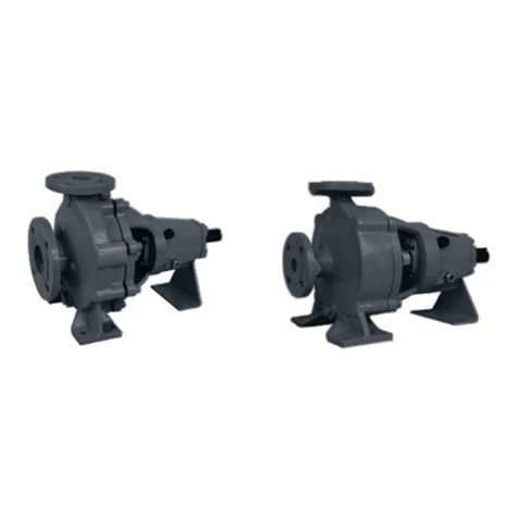
WEL-TECH SG Series User manual

WEL-TECH EQUIPMENTS
Page 1 of 29
SG Series
Self priming non clog pump
USER MANUAL
‘SG’ Series
Plot No. 57/9, Ph I, G.I.D.C. Vatwa,
Ahmedabad, Gujarat, India, 382 445
Ph. No. (079) 32917873, 9725053846
E-mail: jramolia@satyam.net.in
info@weltechpumps.com
Web : www.weltechpumps.com
WEL-TECH EQUIPMENTS

WEL-TECH EQUIPMENTS
Page 2 of 29
SG Series
Table of contents
Introduction
Preface
General information and safety
Warranty
Service and support
Inspection of delivered items
Lifting
Storage
General
Pump description
Construction
Connections
Pump casing
Impeller
Shaft sealing
Bearing bracket
Self priming action
Explanation of designation
Application area
Application guidelines
Installation
Safety
Flushing
Environment
Mounting
Installation of the set
Assembly
Alignment of the coupling
Commissioning
Precautions before commissioning
Preparation lubrication
Preparing the unit for commissioning
Checking the sense of rotation
Preparations start-up
Startup procedure
Temperature
Noise emission
System pressure
Stop procedure
Control
Installation guidelines for pump piping
Maintenance
Precautionary measures
Daily maintenance
Periodicinspection

WEL-TECH EQUIPMENTS
Page 3 of 29
SG Series
Flushing
Ball bearings
Electrical installation
Oil seal
Impeller
Assembly and disassembly
General
Replacing the impeller
Disassembly impeller
Impeller assembly
Replacement of bearings
Disassembly of the ball bearing
Assembly of the ball bearing
Motor replacement
Motor disassembly
Motor assembly
Environmental influences
Cause of failure
Trouble shooting
Fault finding chart
Possible causes
Technical data
Technical specifications
Interchangeability chart for ‘SG’ series
Pump parts
Sectional drawing ‘SG’ series
Part list
Pump disassembly

WEL-TECH EQUIPMENTS
Page 4 of 29
SG Series
Introduction
Preface
This manual provides the information for proper functioning and maintenance
of the pump and contains instructions to prevent possible accidents and damages
and to ensure the safe and smooth functioning of the pump.
Before commissioning of the pump, read the manual carefully and strictly follow the
instructions.
General information and safety instruction
The product supplied by WELTECH has been designed with safety in mind.
•Pump installation area must be kept clean and free of obstructions that may
restrict safe access to the controls and maintenance access point
•The pump nameplate is fitted to each unit must not be removed. Loss of it
could make identification impossible which in turn could cause difficulty in
obtaining spare parts. If accidental loss occurs, contact WTE immediately.
•Access to the equipment should be restricted to the personnel responsible for
installation, operation and maintenance and they must be trained adequately
qualified and supplied with appropriate tools for their respective tasks.
•All personnel that are responsible for installation-operation-maintenance of
the pump must study the product instruction manual before any work is done
and that they will comply with all local and industry based safety instructions
and regulations.
•Safety glasses or goggles should be worn where working with pressurized
systems and hazardous substances. Other personal protection equipments
must be worn where local rules apply.
•Do not wear loose clothing or jewelry which could catch on the controls or
become trapped in the equipments.
•Read the instruction manual prior to installation and confirm that the manual is
relevant copy by comparing pump type on the nameplate and with that on the
manual.
•Note the ‘limits of product application and permissible use’ specified in the
manual. Operation of the equipment beyond those limits will increase the risk
from hazardous and may lead to premature hazardous pump failure.
•Clear and easy access to all controls, gauges, and dials etc. must be
maintained at all the times.
•Hazardous or flammable material must not be stored in pump rooms unless
safe area or racking and suitable containers have been provided.
•Improper installation, operation or maintenance of this WTE product could
result in injury or death.

WEL-TECH EQUIPMENTS
Page 5 of 29
SG Series
Warranty
WTE warrants the pump supplied by us is free from defective material and faulty
workmanship. This warranty holds good for a period of 12 months from the date of
commissioning of the pump or 18 months from the date of dispatch from our factory,
whichever is earlier. Our liability in respect of any complaint is limited to replacing part/parts
free of charge. Ex-works or repairs of the defective part/parts only to the extent that such
replacement/repairs are attributable to our arise solely from faulty workmanship or defective
material.
This warranty holds good only for the products manufactures by us.
Service and support
This manual is intended for technicians and maintenance staff and for those
who are in charge of ordering spare parts.
This manual contains the spare and replacement parts recommended by
WEL-TECH EQUIPMENTS.
The pump sr.no and model number is stated on the nameplate. Please refer
to this number and the other data mentioned on the nameplate when corresponding
or ordering parts.
Inspection of delivered items
•Check the consignment immediately on arrival for damage and conformity with the
advice note.
•In case of damage and/or missing parts, have a report drawn up by the carrier at
once.
Lifting
If a pump or a complete pump unit has to be lifted, the slings should be fixed as
shown in figure 1.
Figure 1 Lifting instruction pump set SG

WEL-TECH EQUIPMENTS
Page 6 of 29
SG Series
General
Note: Proper care should be taken to protect pump and prime mover and/or
paint at contact area of sling or rope at the time of lifting.
Storage
In case the pump is not immediately being used, the pump shaft has to be rotated
manually twice a week.
Pump description
“SG” Pump is self priming centrifugal pump with volute and radial impeller, mounted
overhung on the bearing pedestal. If a spacer type coupling is used, the pump can
easily be dismantled without it being necessary to disturb the piping or to move the
motor or engine.
A lot of parts of these pumps are interchangeable with those of other pump types
from this series.
Construction
Connections
Suction and delivery connections have the same size.
•From G 1 ¼” to 2 ½” (65 mm):internal Whit worth pipe thread
•From 80 to 150 mm: flanges, pressure stage : 10 bar
Pump casing
- Volute design with generously sizes casing with water reserve.
- Window cover for draining and cleaning the pump.
- Filler plug G ¾” on top of the pump casing.
Impeller
Low pressure pumps: semi-open redial 3 or 4 blade centrifugal impeller
High-pressure pumps: closed impeller
Stuffing box
Heavy duty soft gland packed stuffing box with sufficient deep provides minimum
leakage.

WEL-TECH EQUIPMENTS
Page 7 of 29
SG Series
Bearing bracket
- For the whole series there are only four different bearing bracket groups.
- Brackets are fitted dustproof, grease-packed deep groove or angular contact
ball bearing and require no re-greasing .
- Provision for oil lubrication is also available.
- On the pump side. The bearing housing is sealed with an oil seal.
Self priming action
“SG” pumps are of the self priming type. The self priming action relies on the
principle of injection. The pump has to be filled with liquid once. When it has been a
witched on, the air (of gas) is evacuated from the suction line. The aspirated air is
mixed with the liquid contain in the impeller. Through the centrifugal force the
liquid/air mixture from the volute flows to the upper half of the pump casing. In the
generously sized pump casing the liquid can be deaerated. The air escapes to the
discharge line. This causes the liquid to return to the volute (with some pumps the
flow back through the impeller inlet) Where it is aerated and then de-aerated again in
the upper part of the pump casing.
The air is evacuated from the suction line and the liquid level in this piping rises.
Once all air has been evacuated, the pump starts working as a normal centrifugal
pump. A precondition for good functioning is that it should be possible for the
aspirated air to escape without back pressure in the discharge line (open valves!)
The pump has a non return valve, so the suction and discharge lines can not be
siphoned empty, when the pump has been stopped. The remaining liquid in the
pump is always sufficient for the next suction phase.
Figure 2 Self priming action
A: Water / air separation B: Pump casing C: volute
D: impeller E: Back flow opening.
E
D
C
B
A

WEL-TECH EQUIPMENTS
Page 8 of 29
SG Series
Explanation of Designation
Material Designation
Part Material
Pump casing C.I or Bronze
Impeller C.I,S.S Or Bronze
Stuffing box C.I or Bronze
Pump shaft S.S or EN8
Gland packing PTFE+ASBESTOS
Application area
SG pumps used for:
•Clean, contaminated and low viscosity liquids
•The maximum particles size of the impurities depends on the pump impeller size
(see ‘Technical’ specification)
•capacities up to 250m3./Hr.
•Delivery heads up to 35 m
•Max. suction head up to 7.5 m
•Viscosities up to 150 mPas
•Max.solid handling size:41mm
In pumping viscous liquids, you should allow for a decrease in hydraulic performance
and an increase in power. Please ask our advice.
Application guide lines
•Draining building excavation.
•Emptying ponds, ditches and swimming-pools.
•Aboard ships as bile, deck wash and general service pumps.
•Emptying pits and troughs contains waste water.
•Handling fuels
•Condensate extraction pumps etc. Please ask our advice.

WEL-TECH EQUIPMENTS
Page 9 of 29
SG Series
Installation
Safety
•Read this manual carefully before installing and commissioning pump.
Non observance of these instructions may cause serious damage to the pump
and that will not be covered by our guarantee terms. Follow the instructions step
by step.
•Make sure the motor cannot be started when work is done to the pump-motor
combination and running parts are insufficiently shielded.
•When installing the pump unit, take appropriate protection and warning measures
to prevent contact with hot pump parts.
•If danger arises in case of static electricity. The enter pump unit should be earth
properly.
•If there is a danger that the pumped liquid might be harmful to men or the
environment, the user should take appropriate measures for safe drainage.
•If there is any risk of liquid solidifying switch off the pump, drain it and preferably
flush or fill with oil if permitted.
Flushing
Before putting the pump in to operation, drain off any preservative agent and flush
the pump thoroughly with hot water.
Environment
•The foundation must be hard, level and flat
•The area in which the pump unit is to be placed should be adequately ventilated.
A too high ambient temperature and air humidity, as well as a dusty environment
may have a negative effect on the functioning of the pump.
•Around the pump unit there should be enough space to operate and if
necessaries repair the pump.
•Behind the cooling air inlet of the motor there should be a free area of at least ¼
of the electric motor diameter, to ensure unobstructed air supply.
Mounting
Installation of the set
Pump and motor shafts of complete sets are adjusted perfectly in line in the
works. In case of permanents arrangements place the base plate on the foundation
with the aid of shims and tighten the nuts on the foundation bolts carefully.
The check the alignment of pump and motor shafts and realign, if necessary
according to the instruction in Figure 1.

WEL-TECH EQUIPMENTS
Page 10 of 29
SG Series
Assembly
If the pump and the electric motor still have to assembled, proceed as follows:
1. Mount the two coupling halves on the pumps and motor shaft respectively
2. Place the pump on the foundation slab. Secure the pump with bolts.
3. Place the electric motor on the foundation slab. Between the two coupling halves
there should be a gap of 3 mm.
4. Place some copper shims under the feet of the electric motor. Secure the electric
motor with bolts.
5. Align the coupling according to the following instruction.
Alignments of the coupling
1. Place a ruler (A) on the coupling. The ruler should touch both coupling halves across
the whole width. See figure 3.
2. Do the same check against both sides of the coupling near the axis.
3. For all security the alignment is also checked with a pair of outside calipers (B) at 2
diametrically opposite points of the side surfaces of the coupling halves. See fig.3
Figure 3 Aligning of the coupling for SG
Tolerances for aligning coupling
The maximum allowable tolerances in the alignment of the coupling halves are
shown in the table below. See figure 4.
Figure 4
max.
min
Vr
Va
Va

WEL-TECH EQUIPMENTS
Page 11 of 29
SG Series
Aligning tolerances:
outer diameter
coupling
(mm)
Vamin.
(mm) Va Max
(mm) Va-Va min
(mm) Vr max.
70-80 2 4 0.13 0.13
81-95 2 4 0.15 0.15
96-110 2 4 0.18 0.18
111-130 2 4 0.21 0.21
131-140 2 4 0.24 0.24
141-160 0 6 0.27 0.27
Piping
•The piping to the suction and delivery connections must fit exactly and must not be
subject to stress during operation.
•The passage of the suction pipe must be amply dimensioned. This pipe should be as
short as possible and run towards the ump in such a way that no air pockets can
arise. If this is not possible, a venting facility should be provided at the highest point
of the pipe.
•If the inside diameter of the suction pipe is larger than the suction connection of the
pump, an eccentric reducer should be applied to prevent air pockets and whirls.
•If there is a risk that this pressure might be exceeded, for instance because of an
excessive inlet pressure, appropriate measures should be taken by mounting a
safety valve in the piping.
•Sudden changes in the rate of flow can lead to high pressure impulses in the pump
and the piping (water shock). Therefore, don’t use quick acting closing devices,
valves etc.
•It is advisable to install a foot valve when a suction line is long one or static suction
lift is high.
•It is not advisable to have common suction pipe for two or more pumps and similarly
two or more suction lines from different sources. Select the suction line diameter as
function of its length. It must not be smaller than the pump suction connection, it
should also not be too oversized for self priming pump, foot valve is not required
unless suction line is too voluminous or the operating conditions are so favorable
that suction time is longer than approximately 8 minutes.
Mounting accessories
•Mount any parts that may have been supplied separately.
•If the liquid does not flow towards the pump, mount a foot valve at the bottom of
the suction pipe. If necessary, combine this foot valve with a suction strainer to
prevent impurities from being drawn in.
•When mounting, place temporarily (for the first 24 operating hours) fine gauze
between suction flange and suction pipe so as to prevent internal parts from

WEL-TECH EQUIPMENTS
Page 12 of 29
SG Series
Commissioning
being damaged by foreign matter. If the risk of damage continues to exist, mount
a permanent filter.
Precaution before commissioning
Pump
•Check whether the shaft turns freely. Do this by turning the shaft end at the coupling
a few times by hands.
Motor
If driven by an electric motor:
•Check whether the fuses have been mounted.
Engine
If driven by a combustion engine:
•Check whether the room in which the engine is placed is well ventilated.
•Check whether the exhaust of the engine is not obstructed.
•Before starting the engine check the oil level
•Never turn the engine in a closed room.
Preparation of lubrication
Fill the recommended oil through the oil filling orifice for detail see start up procedure
in seal chamber as per the quantity written on the attention plate.
Preparing the unit for commissioning
Proceed as follows both when the unit is put in to operation for the first time and after the
pump has been overhauled:
1. Fully open the stop valve in the suction pipe. Close the delivery stop valve.
2. Fill the pump and the suction pipe with the liquid to be pumped. Through the priming
plug (116) until the liquid starts to over flow.
3. Turn the pump shaft a few times by hand and add more liquid, if necessary.
Checking the sense of rotation
•The sense of rotation of the pump is indicated by an arrow. Check whether the
sense of rotation of the motor corresponds with that of the pump.
•Let the motor run for only a short time and check the sense of rotation.
•If the sense of rotation is not correct, change connecting wire of motor so as to
match with the rotation of pump.
•Mount the coupling guard.

WEL-TECH EQUIPMENTS
Page 13 of 29
SG Series
Preparations start-up
Take the following precautions:
1. Before commissioning the pump, remove any presentative and flush the pump with
hot water (not more than 60’c).
2. Check whether the oil seal chamber is filled with oil. If not, fill with lubricant.
3. Never arrow the seal to turn dry.
4. Check whether the pump shaft turns freely. Do this by turning the shaft end a few
times by hand.
5. Fill the pump with water or the liquid to be handled through the filling plug plug on top
of the pump until the liquid starts to over flow.
6. If oil must not come in to contact with the liquid to be pumped, drain out the oil, rinse
out the oil chamber and fill with a suitable liquid.
If the pump is supplied with a bare shaft end, the user is responsible for the drive
and the assembling with the pump.
A
BE
C
D
Figure 5
A: Pump housing filling hole B: Pump housing filling cleaning cover and drain
C: Oil chamber filling hole D: Oil chamber drain hole
Startup Procedure
1. Check whether it is safe to put the pump in to operation. Make sure any risks to
persons and environment (high pressure, hot temperature, leakage) are absolutely
excluded.
2. A protective cover which completely encloses the coupling must always be used.
3. Start the pump.
4. During the pumps self priming phase, ensure the air can escapes unhindered and,
without any back pressure in the discharge pipe, can flow away.
5. In particular, make sure any pressure cut-off valves are open.
6. Check if connections and seals are not leaking.

WEL-TECH EQUIPMENTS
Page 14 of 29
SG Series
Temperature
The temperature of the pumped liquid may rise to 95 deg. C. above 70 deg. C, the
installer of the pump MUST place the necessary warnings and employ the necessary
protection methods to avoid anyone coming in to contact the pump body.
Noise Emission
1. The noise emission of the SG pump is 80 dBA maximum, measured according to
ISO 2372, in case the pump is used in accordance with the conditions given in the
performance curve.
2. If the pump is used in unusual condition (e.g. in the cavitation zone or wholly above
the curve), the noise level can rise to 85 dBA. And protection measures must be
taken, such as the wearing of ear protectors, or completely encasing the pump within
a sound absorbent shield.
System pressure
The maximum system pressure = maximum working pressure, given on the
technical data sheet. If the pressure could exceed this valve (through an increase in
the rotation speed) a safety valve should be installed in the pipe. Where these
pumps liquid with solid components, there is a great chance that this valve will block.
It is therefore very much to be preferred NEVER to allow the pump to run
faster than specified in the tables.
If no fluid is pumped, leaking appear or if excessive noise is apparent, the
pump must be stopped immediately, refer section cause of failure to determine the problem.
Correct before restarting the pump. If abnormal symptoms persist, the pump must be taken
out of service immediately. Contact us or our appointed agents.
Stop Procedure
1. Turn of the motor.
Always avoid restarting the pump during the emptying phase.
During this procedure, the pump is running in the opposite direction. Restarting it can
result in the impeller coming loose and being damaged and can even cause
breakage of the shaft.
2. If there is any risk of freezing, switch off the pump, drain it and preferably flush or fill
it with oil, if permitted It is also recommended to drain the main piping (suction and
discharge lines).

WEL-TECH EQUIPMENTS
Page 15 of 29
SG Series
Control
If a pump is in operation pay attention to be following:
•The pump should never run dry.
•Never use a stop valve in the suction pipe to control pump capacity. The stop valve
should always be fully opened during operation.
•Check whether the absolute inlet pressure is sufficient, so that no vapour can be
formed.
•Check whether the pressure difference between suction and delivery pressure
corresponds with specifications for the duty point of the pump.

WEL-TECH EQUIPMENTS
Page 16 of 29
SG Series
Installation guidelines for pump piping
Incorrect layout
of suction pipe
Concentric
taper piece
Reduced
suction pipe
Short bend
Insufficient
space around
footvalve
Sufficient
space around
footvalve
Large bend
Increased
suction pipe
Eccentric
taper piece
Correct layout
of suction pipe

WEL-TECH EQUIPMENTS
Page 17 of 29
SG Series
Maintenance
Precautionary measures
•Insufficient, wrong and/or irregular maintenance can lead to malfunctions in the
pump, high repair costs and long term inoperability. Therefore you should carefully
follow the guidelines given in this chapter during maintenance operations on the
pump. Non compliance with prescriptions or warnings may be dangerous for the
user and/or seriously damage the pump/pump group.
•All work should be carried out by suitable trained personnel.
•Pump and piping may contain high pressure liquids, high temperature liquids or/and
hazardous chemical fluids even when the unit has been shut down. Before
dismantling, always allow the pump to cool (20’C) and allow it to drain completely.
•Ensure that the working area is clean, because certain parts such as the mechanical
shaft seals are extremely vulnerable and others have very close tolerances.
•In case of storage:
♦The pump must be operated briefly once a week or alternatively one manually
makes a full revolution of the pump shaft.
♦This ensures a proper circulation of the protective oil.
Daily Maintenance
•Keep both the surface of the pump and the surrounding as clean as possible. This
simplifies inspection (attached marking remain visible).
•Never spray the hot parts of a pump with water; as certain components may crack
due to the sudden cooling and fluid being pumped may spray in to the environment.
Periodic inspection
•The pump should run smoothly and free from noise or vibration
•Shaft alignment and levelness of the base plate
•Gasket joints at pump casing and seal cover and suction / discharge connections
should be inspected for leak.
•Make sure appropriate grade and amount of lubricant is present in bearings and in
the oil chamber .
•Check bearing for excessive wear. Wrong bearing may result in excessive shaft run-
out necessitating frequent seal future.
•Always ensure that the liquid level in the suction line is adequate. Never allow the
suction head to drop below the minimum NPSH (required) by the pump.
Flushing
Because the pump could have been used for corrosive or poisonous liquids, it should
first be thoroughly rinsed out. Flushing the pump out is necessary because the origin of

WEL-TECH EQUIPMENTS
Page 18 of 29
SG Series
the liquid which it contained is not always known and, even after draining the pump
liquid can remain inside.
•Present connections can be used to flush the pump out.
•During this flushing procedure, observe adequate safely regulations and take
environmental protection measures. The wearing of gloves and safety glasses to
protect against possible splashes and hot temperature is advised.
Ball Bearing
The ball bearing are sealed and packed with grease, relubrication is not necessary.
The life time of the bearing of the most heavily loaded pump is approx. 10,000 running
hours, and for the lightest loaded pump it is approx. six times longer.
The lubrication of the bearing plays a very important role and therefore it is
recommended to replace the bearing after 10,000 hours of service, or every three years.
Electrical installation
Maintenance operations on the electric installation may be performed only by trained
and qualified personnel and after disconnecting the electric power supply. Carefully follow
the national safety regulations. Respect the above mentioned regulations also if performing
work while the power supply is still connected.
Stuffing box packing
After the pump is started, the stuffing box will show a certain amount of leakage.
Because of the expansion of the packing fibers, this leakage will gradually decrease.
Make sure that the packing never runs dry. To prevent this, loosen the gland nuts to
the extent that the stuffing box leaks drop wise. As soon as the pump has reached
the proper temperature (and leakage is still too much) the gland can be adjusted
permanently.
•Tighten both gland nuts, one after the other, a quarter turn.
•Wait 15 minutes after each adjustment before making the next adjustment.
•Continue in this way until an acceptable drop wise leakage has been attained.(20-30
drops/minutes)
Impeller
If there is decline in the performance characteristics of the pump when neither the
installation nor the working point has been changed it is 90% certain that there is wear
on the impeller. How quickly this wear occurs is dependent upon the type of liquid being
pumped. There is a clearance between the impeller and the pump casing. This
clearance becomes grater through wear. In order to check this, the pump must be
dismantled and the dimensions A as shown in figure 7 should be measured. It must not
exceed 0.5 mm.

WEL-TECH EQUIPMENTS
Page 19 of 29
SG Series
The dismantling and re-assembly instruction are given in the following points.
C2 - C1 = A
Figure 7
Assembly and Disassembly
General
•When the servicing the pumps, see to a clean working environment because certain
parts, say, the mechanical seal, are extremely vulnerable, other part having close
tolerances. Check that the parts have not been damaged in transit. In particular,
inspect the spigots mating and sealing faces, etc.
•Loctite liquid securing type 243 in used for securing the impeller screw or impeller
bolt.
•When Loctite is used, first degrease the parts properly. The Loctite must be applied
in sufficient Quantities both internally and the bolts tightened up to the torque
settings shown in table below :
Max. tightening torque Nm.
Material bolt M-6 M-8 M-10 M-12 M-16 Application
8.8 11 25 51 87 215
Bearing bracket
Internal piece.
A2 / A4 8.5 21 42 70 173 Impeller
Replacing the impeller
Also refer to sectional drawings

WEL-TECH EQUIPMENTS
Page 20 of 29
SG Series
Disassembly impeller
` Figure 8
112
102
119
1. Drain out the drain liquid from the oil chamber by removing the oil drain plug (128)
2A. Bearing bracket 00, 0 and 0+
a) Detach bearing bracket by loosening bolts (119).
b) Undo the impeller screw (112).
2B. Bearing bracket 1 and 2:
a) Detach bearing bracket by loosening bolts (119).
b) Disassemble ST.BOX with bearing from pump casing by loosening bolts (119).
c) Undo the impeller bolt.
d) Remove washer.
3. Next detach the impeller (102) using a coupling puller.
Table of contents
Other WEL-TECH Water Pump manuals
Popular Water Pump manuals by other brands

Stuart Turner
Stuart Turner AQUABOOST iMatic 0304 1S-CMT/8 450 Installation, operation & maintenance instructions

Samoa
Samoa 560 230 Technical service guide

Crane
Crane Deming 4310 Series Installation, operation & maintenance manual

Tomahawk
Tomahawk TW3H Operation manual

Truper
Truper BOS-1SP manual

KNF
KNF Labor N035.18 Operating instruction

Wilden
Wilden Original Series Engineering, operation & maintenance

Zoeller
Zoeller 1052Q Quick reference guide

Grundfos
Grundfos PS.W.04-20 Installation and operating instructions

Desmi
Desmi SA50-T HATZ 1B20 Operation and maintenance instructions

Graf
Graf 202561 Instructions for installation

Oypla Leisure
Oypla Leisure 4002 user manual