Smith-Root UBC-24 User manual
07292.13 UBC-24 Man
USER'S GUIDE
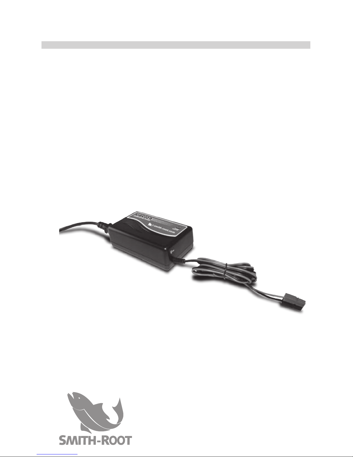
UBC-24
UNIVERSAL BATTERY CHARGER
www.smith-root.com
SPECIFICATIONS
Input Rating: Nominal 90-264VAC/47-63Hz
Maximum Output Power: 60W
Load Regulation: <200mV
Line Regulation: <100mV
Switch Frequency: ≈40 kHz
Temperature Range: -10°C to +40°C
Ripple: <100mVp-p
Efficiency (At 100%
Load):
80%
Insulation Class: Class I
Electrical Safety: UL 60601-1, EN 60601-1, EN
60950, EN 60335-2-29
EMC Standards: EN 60601-1-2 (Medical), EN
61000-6-3 (Emission), EN
61000-6-1 (Immunity)
Timer: 2hr 330% (also available with
other values)
Input Connection: 3 pin IEC 320 (input cordset
not included)
Output Connection: Battery clips
Dimensions/Weight: 5.31” x 3.15” x 1.73” (135 x 80 x
44mm)/ 0.77 lbs. (350g)
Items manufactured by companies other than Smith-Root carry
the original manufacturer’s warranty. Please contact product
manufacturer for return instructions.
All Smith-Root, Inc. manufactured products are covered by a one year warranty.
Credit & Refund Policy: Customers returning equipment, in new condition, will
be given credit five days from the date of the return. A return authorization
must accompany returns. Valid equipment returns include, but are not limited
to, ordering incorrect equipment, funding deficits, and defective equipment
returned for reimbursement. All returns are subject to a restocking fee and
applicable shipping charges. The restocking fee is figured at 10% of the
purchase price but not less than $20.00. Customers receiving equipment in
damaged condition will be referred to the shipping company for insurance
reimbursement.
07292.13 UBC-24 Manual - © 2015 Smith-Root, Inc.
BATTERY CYCLE LOG
Use this form* to record the number of times a
battery has been cycled:
DATE: SERIAL #: NOTES:
BATTERY CYCLE LOG
Use this form to record the number of times a
battery has been cycled:
DATE: SERIAL #: NOTES:
BATTERY CYCLE LOG
Use this form to record the number of times a
battery has been cycled:
DATE: SERIAL #: NOTES:
STORAGE INSTRUCTIONS
• When not in use, store the charger indoors in
a cool dry place, preferably with its original
packing and carton.
• Place these instructions with the charger
during storage.
MAINTENANCE AND CLEANING
• Very little maintenance is required other than
protecting the charger from damage and
weather.
• Coil cord when not in use.
• Clean case and cords with a slightly damp
cloth.
• Examine cords for damage periodically and re-
place if necessary with manufacturer approved
parts.
BAT-01 BATTERY ANALYSIS TOOL
The Battery Analysis
Tool is an accessory
designed to oper-
ate with existing
Smith-Root batter-
ies and chargers. Its
purpose is to test
back-pack Electro-
fisher batteries, and
to demonstrate in a
clear concise manner
the amount of usable life remaining in batteries
being tested.
CHARGING OTHER SMITH-
ROOT BATTERIES
The UBC-24 Battery Charger is designed to
charge batteries for LR-Series Electrofisher Sys-
tems. However, users that have an inventory of
older-style Smith-Root electrofisher batteries can
charge them with the following adapters:
The Model 12 Battery to LR-Series Charger
Adapter (#07458) will allow you to charge Model
12 Batteries (#03298 & #02595) with the current
model of UBC-24.
The LR-Series Battery to Model 12 Adapter Ca-
ble (#07459) will allow you to charge LR-Series
lead-acid batteries with our older, Model 12 style
BC-24 Battery Charger (#04954) with a 4-pin
connector.
The Lithium Battery Adapter Cable (#10791) al-
lows charging of 9.6Ah Lithium batteries with the
UBC. It is supplied with each Lithium battery but
is also available separately.
BAT-01
UBC-24
From AC
Battery
Under
Test
Bat-01 Hookup
BAT-01 Battery Analysis Tool .........#08041
Model 12 Battery to LR-Series Charger ..07458
LR-Series Battery to Model 12 Charger ..07459
Lithium Battery Cable.................................. 10791
7 8 9
10
Phone: (360) 573-0202 • Email: info@smith-root.com
Vancouver, WA USA
12Ah 24V
The 12 Amp-hour battery provides
extended electrofishing time as
compared to a standard 7Ah
battery.
Weight ..........14.75 lbs.
Part # ................ 06682
7Ah 24V
Our 7 Amp-hour battery comes
standard with the LR-20 and LR-24
electrofishers combos and provides
a good balance between weight and
power.
Weight.............10.3 lbs.
Part # ..............06681
24V 9.6AH
Our lithium iron phosphate battery
is half the weight of our lead-acid
batteries, with a much higher
recharge capacity.
LITHIUM BATTERY ADAPTER
(10791) is included with each battery
purchased.
Weight.............5.95 lbs.
Part # .............. 10765
SMITH-ROOT BATTERIES
We currently offer two lead-acid batteries for SRI
Backpack Electrofishers. Both are 24 volt, sealed deep
discharge-rated, lead acid batteries.
Also available is our new lightweight lithium-iron phos-
phate battery.
To learn more about batteries, visit:
www.smith-root.com/electrofishers/batteries or consult
the instruction sheet supplied with your Smith-Root
battery.
*To preserve the integrity of your UBC-24 instruction sheet, photocopy and print out this section for your own use.

LEDS INDICATE FOLLOWING
CHARGE STATUS
FAST CHARGE
The charger is in constant current mode.
Charge current is at its maximum.
FINAL CHARGE
The charger is in constant voltage
mode. Charge current is less than its
maximum.
The battery is normally 80-95%
charged. The charger stays in this mode
until the charge current decreases to charge
termination level.
FLOAT (Standby/Ready)
The charger is in standby mode.
The battery is fully charged. The LED
changes to green. Remove battery from
charger. Do not leave charged battery
on charger for extended periods of time.
HOW TO CHARGE BATTERIES
1. The charger and battery should be placed in a
well-ventilated area during charging.
2. Do not connect the charger to the wall socket
before it is connected to the battery.
3. Verify that the polarity is correct and connect
the charger cable: Red to red; black to black.
4. Connect the charger to the wall socket.
5. When charging is finished, disconnect the
charger from the wall socket, then disconnect
the battery. Do not leave batteries on the char-
ger once fully charged.
CONNECTORS AND
INDICATORS
INPUT POWER CORD: The input power plug is a
standard 120VAC three-pin with ground. Note: A
cord-set specific to the customer’s specified coun-
try will be substituted upon request.
OUTPUT CORD AND CONNECTOR: The connec-
tor on the end of the cord is wired to plug directly
into the quick-disconnect connector on the battery
pack.
CHARGE STATUS LED: The top panel indicator
LED indicates the battery’s state of charge (see
page 4).
Users that have
an inventory
of older style
Smith-Root elec-
trofisher batter-
ies with different
terminal connec-
tors can charge
them with the
UBC-24 using
adapter cables available from SRI (See page 8).
CHARGING SRI LITHIUM BATTERIES
Use the adapter cable provided with all SRI 9.6Ah
Lithium Batteries (#10791) with the UBC for
charging purposes.
The use of any other charger than the UBC-24 to
charge lithium batteries will result in damage. Do
not use older style Smith-Root chargers for lithium
batteries.
BAT-01
UBC-24
From AC
Battery
Under
Test
CONTENTS
CHARGER DESCRIPTION ................................. 1
OPERATIONAL INSTRUCTIONS ................... 2
CHARGING ............................................................ 3
LEDS AND CHARGE STATUS.........................4
CONNECTORS AND INDICATORS ............... 5
CHARGING LITHIUM BATTERIES ................. 5
CHARGER OPERATING INSTRUCTIONS ...6
STORAGE INSTRUCTIONS .............................. 7
MAINTENANCE AND CLEANING ................. 7
CHARGING OTHER SRI BATTERIES............ 8
SPECIFICATIONS ................................................9
BATTERY CYCLE LOG..................................... 10
CHARGER DESCRIPTION
The UBC-24 Battery Charger is a fully-auto-
matic charger designed to charge lead-acid
and lithium batteries for the LR-24, LR-20
Series (and earlier Smith-Root 24V models)
electrofisher systems utilizing a three-stage
charging sequence.
The battery charger is only designed for indoor use
and should not come into contact with water or dust. In
order to avoid overheating, the charger should not be
covered when it is in use.
Chargers filled with molding material are splash-proof,
but must not be immersed in water over long periods
of time.
The wall socket should be easily accessible. If an op-
erational error occurs, the plug should be immediately
removed from the socket.
The charger contains dangerous voltages and the cover
should not be removed. All service or maintenance
work should be carried out by qualified personnel who
can get assistance by contacting the manufacturer’s
agent.
A fuse protects the product against short-circuiting and
overloading.
CHARGER OPERATING
INSTRUCTIONS
This charger is suitable for use
with all types of lead acid and
lithium batteries, including the
new types of maintenance-free
and gelled electrolyte batteries.
1. Connect charger to battery.
2. Connect the charger to the
AC power supply. The state
of charge is shown by the
LED indicators on the battery
charger as follows. The red
“Charge” LED will light to
indicate that the battery is
correctly connected and is
charging. The indicator LED
will turn green when the
battery is fully charged.
3. The length of time needed for
recharging will depend on the
size and depth of discharge of
the battery. A full charging of
a large battery may take up to
12 hours.
4. For best results, the charger
should be allowed to complete its full cycle as
indicated by the green LED.
OPERATIONAL INSTRUCTIONS
Read these instructions before using the charger
CAUTION: Old lead-acid batteries usually have a
reduced capacity and are difficult to charge. Batteries
in this condition should be replaced.
BAT-01
UBC-24
From AC
Battery
Under
Test
WARNING: Explosive gases can arise while
charging lead-acid batteries. Avoid sparks
and open flames. Verify that there is adequate
ventilation while charging. The charger should
not be used in the vicinity of flammable gases. Avoid
contact with oils, grease, etc., as most types of plastic
can be broken down by chemicals and solvents.
Explosive gases can arise while charging. Avoid sparks and open flames. Verify
that there is adequate ventilation while charging. The charger should not be used
in the vicinity of flammable anesthesia gases. Avoid chargers with plastic casing
coming into contact with oils, grease, etc., as most types of plastic can be broken
down by chemicals and solvents.
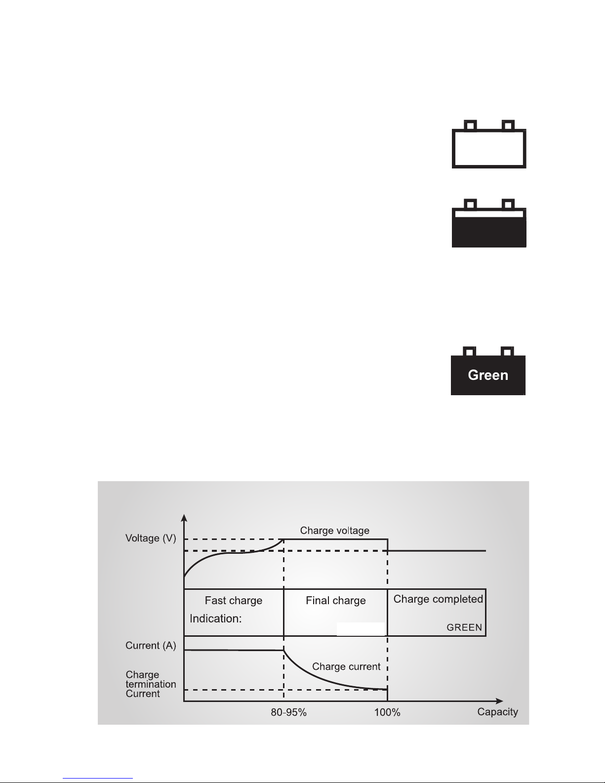
Fast charge
The charger is in constant current mode.
Charge current is at its maximum.
Final charge
The charger is in constant voltage mode.
Charge current is less than its maximum.
The battery is normally 80-95% charged.
The charger stays in this mode until the charge current
decreases to charge termination level.
Float (Standby / Ready)
The charger is in standby mode.
The battery is fully charged. The LED changes to green.
The charge voltage is at standby level, which means the charger
can continue to be connected to the battery.
The charger can return to rapid charging if the battery is used.
WARNING
LED’s INDICATE FOLLOWING CHARGE STATUS
Charging diagram
RED RED
Red
Red
Explosive gases can arise while charging. Avoid sparks and open flames. Verify
that there is adequate ventilation while charging. The charger should not be used
in the vicinity of flammable anesthesia gases. Avoid chargers with plastic casing
coming into contact with oils, grease, etc., as most types of plastic can be broken
down by chemicals and solvents.
Fast charge
The charger is in constant current mode.
Charge current is at its maximum.
Final charge
The charger is in constant voltage mode.
Charge current is less than its maximum.
The battery is normally 80-95% charged.
The charger stays in this mode until the charge current
decreases to charge termination level.
Float (Standby / Ready)
The charger is in standby mode.
The battery is fully charged. The LED changes to green.
The charge voltage is at standby level, which means the charger
can continue to be connected to the battery.
The charger can return to rapid charging if the battery is used.
WARNING
LED’s INDICATE FOLLOWING CHARGE STATUS
Charging diagram
RED RED
Red
Red
Orange
Explosive gases can arise while charging. Avoid sparks and open flames. Verify
that there is adequate ventilation while charging. The charger should not be used
in the vicinity of flammable anesthesia gases. Avoid chargers with plastic casing
coming into contact with oils, grease, etc., as most types of plastic can be broken
down by chemicals and solvents.
Fast charge
The charger is in constant current mode.
Charge current is at its maximum.
Final charge
The charger is in constant voltage mode.
Charge current is less than its maximum.
The battery is normally 80-95% charged.
The charger stays in this mode until the charge current
decreases to charge termination level.
Float (Standby / Ready)
The charger is in standby mode.
The battery is fully charged. The LED changes to green.
The charge voltage is at standby level, which means the charger
can continue to be connected to the battery.
The charger can return to rapid charging if the battery is used.
WARNING
LED’s INDICATE FOLLOWING CHARGE STATUS
Charging diagram
RED RED
Red
Red
ORANGE
1
UBC-24
Power source
Battery
Connector
4
2
5
3
6
CHARGE
INDICATOR
UNIVERSAL BATTERYCHARGER
UBC-24UBC-24UBC-24
1
0
1
1
2
a
1. Input Power Cord
2.Charge Status Led
3.Output Cord, Connector
1
2
3
INSET: Lithium Battery
Adapter Cable
IMPORTANT SAFETY NOTE: When disconnecting the
battery from the charger, switch off or unplug the AC
supply to the charger first. This precaution will elimi-
nate any risk of gas explosion due to arcing.
BAT-01
UBC-24
From AC
Battery
Under
Test
BAT-01
UBC-24
From AC
Battery
Under
Test
Explosive gases can arise while charging. Avoid sparks and open flames. Verify
that there is adequate ventilation while charging. The charger should not be used
in the vicinity of flammable anesthesia gases. Avoid chargers with plastic casing
coming into contact with oils, grease, etc., as most types of plastic can be broken
down by chemicals and solvents.
Fast charge
The charger is in constant current mode.
Charge current is at its maximum.
Final charge
The charger is in constant voltage mode.
Charge current is less than its maximum.
The battery is normally 80-95% charged.
The charger stays in this mode until the charge current
decreases to charge termination level.
Float (Standby / Ready)
The charger is in standby mode.
The battery is fully charged. The LED changes to green.
The charge voltage is at standby level, which means the charger
can continue to be connected to the battery.
The charger can return to rapid charging if the battery is used.
WARNING
LED’s INDICATE FOLLOWING CHARGE STATUS
Charging diagram
RED RED
Red
Red
Orange
Beginning
Charging
Charging
Explosive gases can arise while charging. Avoid sparks and open flames. Verify
that there is adequate ventilation while charging. The charger should not be used
in the vicinity of flammable anesthesia gases. Avoid chargers with plastic casing
coming into contact with oils, grease, etc., as most types of plastic can be broken
down by chemicals and solvents.
Fast charge
The charger is in constant current mode.
Charge current is at its maximum.
Final charge
The charger is in constant voltage mode.
Charge current is less than its maximum.
The battery is normally 80-95% charged.
The charger stays in this mode until the charge current
decreases to charge termination level.
Float (Standby / Ready)
The charger is in standby mode.
The battery is fully charged. The LED changes to green.
The charge voltage is at standby level, which means the charger
can continue to be connected to the battery.
The charger can return to rapid charging if the battery is used.
WARNING
LED’s INDICATE FOLLOWING CHARGE STATUS
Charging diagram
RED RED
Red
Red
Fully Charged
USER'S GUIDE
UBC-24
UNIVERSAL BATTERY CHARGER

LEDS INDICATE FOLLOWING
CHARGE STATUS
FAST CHARGE
The charger is in constant current mode.
Charge current is at its maximum.
FINAL CHARGE
The charger is in constant voltage
mode. Charge current is less than its
maximum.
The battery is normally 80-95%
charged. The charger stays in this mode
until the charge current decreases to charge
termination level.
FLOAT (Standby/Ready)
The charger is in standby mode.
The battery is fully charged. The LED
changes to green. Remove battery from
charger. Do not leave charged battery
on charger for extended periods of time.
HOW TO CHARGE BATTERIES
1. The charger and battery should be placed in a
well-ventilated area during charging.
2. Do not connect the charger to the wall socket
before it is connected to the battery.
3. Verify that the polarity is correct and connect
the charger cable: Red to red; black to black.
4. Connect the charger to the wall socket.
5. When charging is finished, disconnect the
charger from the wall socket, then disconnect
the battery. Do not leave batteries on the char-
ger once fully charged.
CONNECTORS AND
INDICATORS
INPUT POWER CORD: The input power plug is a
standard 120VAC three-pin with ground. Note: A
cord-set specific to the customer’s specified coun-
try will be substituted upon request.
OUTPUT CORD AND CONNECTOR: The connec-
tor on the end of the cord is wired to plug directly
into the quick-disconnect connector on the battery
pack.
CHARGE STATUS LED: The top panel indicator
LED indicates the battery’s state of charge (see
page 4).
Users that have
an inventory
of older style
Smith-Root elec-
trofisher batter-
ies with different
terminal connec-
tors can charge
them with the
UBC-24 using
adapter cables available from SRI (See page 8).
CHARGING SRI LITHIUM BATTERIES
Use the adapter cable provided with all SRI 9.6Ah
Lithium Batteries (#10791) with the UBC for
charging purposes.
The use of any other charger than the UBC-24 to
charge lithium batteries will result in damage. Do
not use older style Smith-Root chargers for lithium
batteries.
BAT-01
UBC-24
From AC
Battery
Under
Test
CONTENTS
CHARGER DESCRIPTION ................................. 1
OPERATIONAL INSTRUCTIONS ................... 2
CHARGING ............................................................ 3
LEDS AND CHARGE STATUS.........................4
CONNECTORS AND INDICATORS ............... 5
CHARGING LITHIUM BATTERIES ................. 5
CHARGER OPERATING INSTRUCTIONS ...6
STORAGE INSTRUCTIONS .............................. 7
MAINTENANCE AND CLEANING ................. 7
CHARGING OTHER SRI BATTERIES............ 8
SPECIFICATIONS ................................................9
BATTERY CYCLE LOG..................................... 10
CHARGER DESCRIPTION
The UBC-24 Battery Charger is a fully-auto-
matic charger designed to charge lead-acid
and lithium batteries for the LR-24, LR-20
Series (and earlier Smith-Root 24V models)
electrofisher systems utilizing a three-stage
charging sequence.
The battery charger is only designed for indoor use
and should not come into contact with water or dust. In
order to avoid overheating, the charger should not be
covered when it is in use.
Chargers filled with molding material are splash-proof,
but must not be immersed in water over long periods
of time.
The wall socket should be easily accessible. If an op-
erational error occurs, the plug should be immediately
removed from the socket.
The charger contains dangerous voltages and the cover
should not be removed. All service or maintenance
work should be carried out by qualified personnel who
can get assistance by contacting the manufacturer’s
agent.
A fuse protects the product against short-circuiting and
overloading.
CHARGER OPERATING
INSTRUCTIONS
This charger is suitable for use
with all types of lead acid and
lithium batteries, including the
new types of maintenance-free
and gelled electrolyte batteries.
1. Connect charger to battery.
2. Connect the charger to the
AC power supply. The state
of charge is shown by the
LED indicators on the battery
charger as follows. The red
“Charge” LED will light to
indicate that the battery is
correctly connected and is
charging. The indicator LED
will turn green when the
battery is fully charged.
3. The length of time needed for
recharging will depend on the
size and depth of discharge of
the battery. A full charging of
a large battery may take up to
12 hours.
4. For best results, the charger
should be allowed to complete its full cycle as
indicated by the green LED.
OPERATIONAL INSTRUCTIONS
Read these instructions before using the charger
CAUTION: Old lead-acid batteries usually have a
reduced capacity and are difficult to charge. Batteries
in this condition should be replaced.
BAT-01
UBC-24
From AC
Battery
Under
Test
WARNING: Explosive gases can arise while
charging lead-acid batteries. Avoid sparks
and open flames. Verify that there is adequate
ventilation while charging. The charger should
not be used in the vicinity of flammable gases. Avoid
contact with oils, grease, etc., as most types of plastic
can be broken down by chemicals and solvents.
Explosive gases can arise while charging. Avoid sparks and open flames. Verify
that there is adequate ventilation while charging. The charger should not be used
in the vicinity of flammable anesthesia gases. Avoid chargers with plastic casing
coming into contact with oils, grease, etc., as most types of plastic can be broken
down by chemicals and solvents.
Fast charge
The charger is in constant current mode.
Charge current is at its maximum.
Final charge
The charger is in constant voltage mode.
Charge current is less than its maximum.
The battery is normally 80-95% charged.
The charger stays in this mode until the charge current
decreases to charge termination level.
Float (Standby / Ready)
The charger is in standby mode.
The battery is fully charged. The LED changes to green.
The charge voltage is at standby level, which means the charger
can continue to be connected to the battery.
The charger can return to rapid charging if the battery is used.
WARNING
LED’s INDICATE FOLLOWING CHARGE STATUS
Charging diagram
RED RED
Red
Red
Orange
Explosive gases can arise while charging. Avoid sparks and open flames. Verify
that there is adequate ventilation while charging. The charger should not be used
in the vicinity of flammable anesthesia gases. Avoid chargers with plastic casing
coming into contact with oils, grease, etc., as most types of plastic can be broken
down by chemicals and solvents.
Fast charge
The charger is in constant current mode.
Charge current is at its maximum.
Final charge
The charger is in constant voltage mode.
Charge current is less than its maximum.
The battery is normally 80-95% charged.
The charger stays in this mode until the charge current
decreases to charge termination level.
Float (Standby / Ready)
The charger is in standby mode.
The battery is fully charged. The LED changes to green.
The charge voltage is at standby level, which means the charger
can continue to be connected to the battery.
The charger can return to rapid charging if the battery is used.
WARNING
LED’s INDICATE FOLLOWING CHARGE STATUS
Charging diagram
RED RED
Red
Red
ORANGE
1
UBC-24
Power source
Battery
Connector
4
2
5
3
6
CHARGE
INDICATOR
UNIVERSAL BATTERYCHARGER
UBC-24UBC-24UBC-24
1
0
1
1
2
a
1. Input Power Cord
2.Charge Status Led
3.Output Cord, Connector
1
2
3
INSET: Lithium Battery
Adapter Cable
IMPORTANT SAFETY NOTE: When disconnecting the
battery from the charger, switch off or unplug the AC
supply to the charger first. This precaution will elimi-
nate any risk of gas explosion due to arcing.
BAT-01
UBC-24
From AC
Battery
Under
Test
BAT-01
UBC-24
From AC
Battery
Under
Test
Explosive gases can arise while charging. Avoid sparks and open flames. Verify
that there is adequate ventilation while charging. The charger should not be used
in the vicinity of flammable anesthesia gases. Avoid chargers with plastic casing
coming into contact with oils, grease, etc., as most types of plastic can be broken
down by chemicals and solvents.
Fast charge
The charger is in constant current mode.
Charge current is at its maximum.
Final charge
The charger is in constant voltage mode.
Charge current is less than its maximum.
The battery is normally 80-95% charged.
The charger stays in this mode until the charge current
decreases to charge termination level.
Float (Standby / Ready)
The charger is in standby mode.
The battery is fully charged. The LED changes to green.
The charge voltage is at standby level, which means the charger
can continue to be connected to the battery.
The charger can return to rapid charging if the battery is used.
WARNING
LED’s INDICATE FOLLOWING CHARGE STATUS
Charging diagram
RED RED
Red
Red
Orange
Beginning
Charging
Charging
Explosive gases can arise while charging. Avoid sparks and open flames. Verify
that there is adequate ventilation while charging. The charger should not be used
in the vicinity of flammable anesthesia gases. Avoid chargers with plastic casing
coming into contact with oils, grease, etc., as most types of plastic can be broken
down by chemicals and solvents.
Fast charge
The charger is in constant current mode.
Charge current is at its maximum.
Final charge
The charger is in constant voltage mode.
Charge current is less than its maximum.
The battery is normally 80-95% charged.
The charger stays in this mode until the charge current
decreases to charge termination level.
Float (Standby / Ready)
The charger is in standby mode.
The battery is fully charged. The LED changes to green.
The charge voltage is at standby level, which means the charger
can continue to be connected to the battery.
The charger can return to rapid charging if the battery is used.
WARNING
LED’s INDICATE FOLLOWING CHARGE STATUS
Charging diagram
RED RED
Red
Red
Fully Charged
USER'S GUIDE
UBC-24
UNIVERSAL BATTERY CHARGER
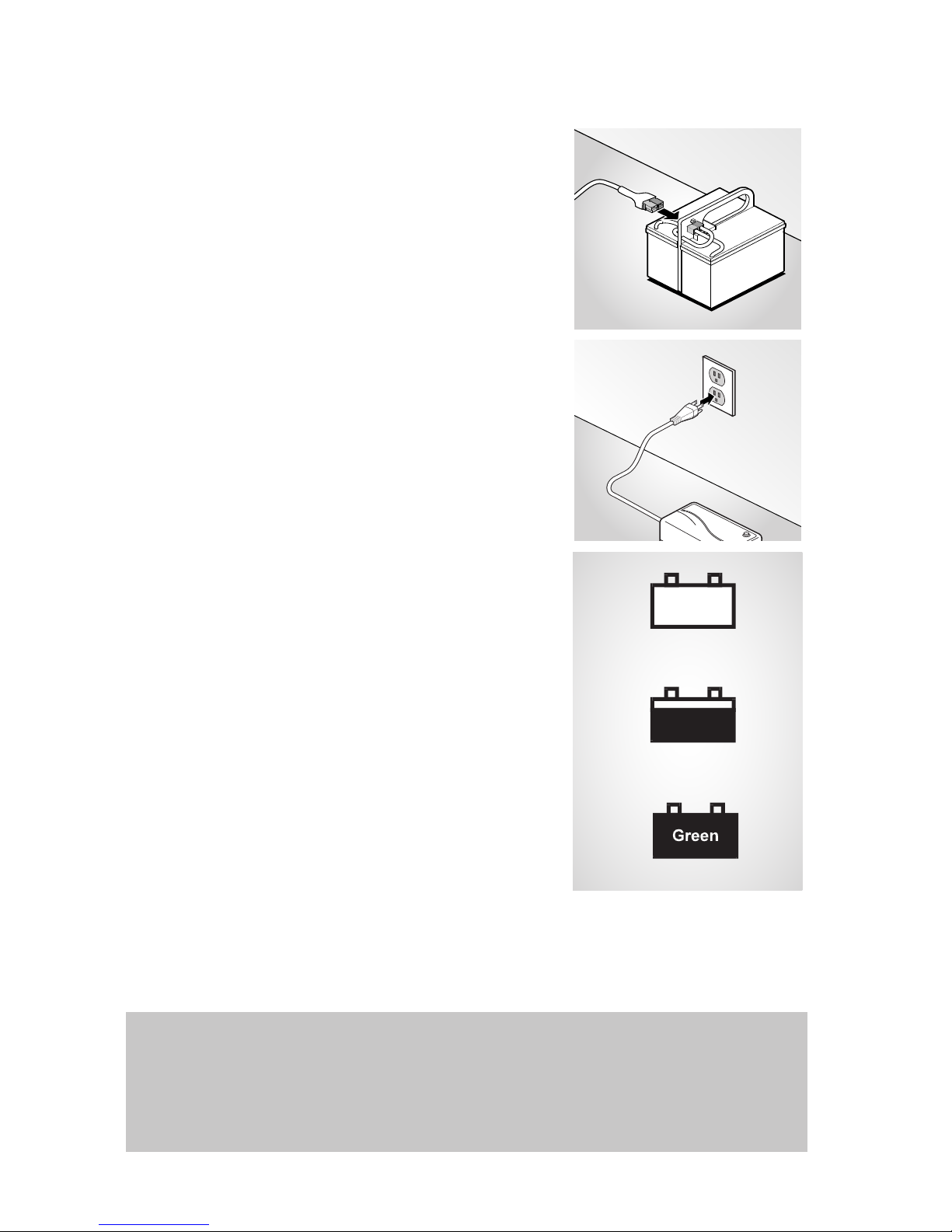

07292.13 UBC-24 Man
USER'S GUIDE
UBC-24
UNIVERSAL BATTERY CHARGER
www.smith-root.com
SPECIFICATIONS
Input Rating: Nominal 90-264VAC/47-63Hz
Maximum Output Power: 60W
Load Regulation: <200mV
Line Regulation: <100mV
Switch Frequency: ≈40 kHz
Temperature Range: -10°C to +40°C
Ripple: <100mVp-p
Efficiency (At 100%
Load):
80%
Insulation Class: Class I
Electrical Safety: UL 60601-1, EN 60601-1, EN
60950, EN 60335-2-29
EMC Standards: EN 60601-1-2 (Medical), EN
61000-6-3 (Emission), EN
61000-6-1 (Immunity)
Timer: 2hr 330% (also available with
other values)
Input Connection: 3 pin IEC 320 (input cordset
not included)
Output Connection: Battery clips
Dimensions/Weight: 5.31” x 3.15” x 1.73” (135 x 80 x
44mm)/ 0.77 lbs. (350g)
Items manufactured by companies other than Smith-Root carry
the original manufacturer’s warranty. Please contact product
manufacturer for return instructions.
All Smith-Root, Inc. manufactured products are covered by a one year warranty.
Credit & Refund Policy: Customers returning equipment, in new condition, will
be given credit five days from the date of the return. A return authorization
must accompany returns. Valid equipment returns include, but are not limited
to, ordering incorrect equipment, funding deficits, and defective equipment
returned for reimbursement. All returns are subject to a restocking fee and
applicable shipping charges. The restocking fee is figured at 10% of the
purchase price but not less than $20.00. Customers receiving equipment in
damaged condition will be referred to the shipping company for insurance
reimbursement.
07292.13 UBC-24 Manual - © 2015 Smith-Root, Inc.
BATTERY CYCLE LOG
Use this form* to record the number of times a
battery has been cycled:
DATE: SERIAL #: NOTES:
BATTERY CYCLE LOG
Use this form to record the number of times a
battery has been cycled:
DATE: SERIAL #: NOTES:
BATTERY CYCLE LOG
Use this form to record the number of times a
battery has been cycled:
DATE: SERIAL #: NOTES:
STORAGE INSTRUCTIONS
• When not in use, store the charger indoors in
a cool dry place, preferably with its original
packing and carton.
• Place these instructions with the charger
during storage.
MAINTENANCE AND CLEANING
• Very little maintenance is required other than
protecting the charger from damage and
weather.
• Coil cord when not in use.
• Clean case and cords with a slightly damp
cloth.
• Examine cords for damage periodically and re-
place if necessary with manufacturer approved
parts.
BAT-01 BATTERY ANALYSIS TOOL
The Battery Analysis
Tool is an accessory
designed to oper-
ate with existing
Smith-Root batter-
ies and chargers. Its
purpose is to test
back-pack Electro-
fisher batteries, and
to demonstrate in a
clear concise manner
the amount of usable life remaining in batteries
being tested.
CHARGING OTHER SMITH-
ROOT BATTERIES
The UBC-24 Battery Charger is designed to
charge batteries for LR-Series Electrofisher Sys-
tems. However, users that have an inventory of
older-style Smith-Root electrofisher batteries can
charge them with the following adapters:
The Model 12 Battery to LR-Series Charger
Adapter (#07458) will allow you to charge Model
12 Batteries (#03298 & #02595) with the current
model of UBC-24.
The LR-Series Battery to Model 12 Adapter Ca-
ble (#07459) will allow you to charge LR-Series
lead-acid batteries with our older, Model 12 style
BC-24 Battery Charger (#04954) with a 4-pin
connector.
The Lithium Battery Adapter Cable (#10791) al-
lows charging of 9.6Ah Lithium batteries with the
UBC. It is supplied with each Lithium battery but
is also available separately.
BAT-01
UBC-24
From AC
Battery
Under
Test
Bat-01 Hookup
BAT-01 Battery Analysis Tool .........#08041
Model 12 Battery to LR-Series Charger ..07458
LR-Series Battery to Model 12 Charger ..07459
Lithium Battery Cable.................................. 10791
7 8 9
10
Phone: (360) 573-0202 • Email: info@smith-root.com
Vancouver, WA USA
12Ah 24V
The 12 Amp-hour battery provides
extended electrofishing time as
compared to a standard 7Ah
battery.
Weight ..........14.75 lbs.
Part # ................ 06682
7Ah 24V
Our 7 Amp-hour battery comes
standard with the LR-20 and LR-24
electrofishers combos and provides
a good balance between weight and
power.
Weight.............10.3 lbs.
Part # ..............06681
24V 9.6AH
Our lithium iron phosphate battery
is half the weight of our lead-acid
batteries, with a much higher
recharge capacity.
LITHIUM BATTERY ADAPTER
(10791) is included with each battery
purchased.
Weight.............5.95 lbs.
Part # .............. 10765
SMITH-ROOT BATTERIES
We currently offer two lead-acid batteries for SRI
Backpack Electrofishers. Both are 24 volt, sealed deep
discharge-rated, lead acid batteries.
Also available is our new lightweight lithium-iron phos-
phate battery.
To learn more about batteries, visit:
www.smith-root.com/electrofishers/batteries or consult
the instruction sheet supplied with your Smith-Root
battery.
*To preserve the integrity of your UBC-24 instruction sheet, photocopy and print out this section for your own use.

07292.13 UBC-24 Man
USER'S GUIDE
UBC-24
UNIVERSAL BATTERY CHARGER
www.smith-root.com
SPECIFICATIONS
Input Rating: Nominal 90-264VAC/47-63Hz
Maximum Output Power: 60W
Load Regulation: <200mV
Line Regulation: <100mV
Switch Frequency: ≈40 kHz
Temperature Range: -10°C to +40°C
Ripple: <100mVp-p
Efficiency (At 100%
Load):
80%
Insulation Class: Class I
Electrical Safety: UL 60601-1, EN 60601-1, EN
60950, EN 60335-2-29
EMC Standards: EN 60601-1-2 (Medical), EN
61000-6-3 (Emission), EN
61000-6-1 (Immunity)
Timer: 2hr 330% (also available with
other values)
Input Connection: 3 pin IEC 320 (input cordset
not included)
Output Connection: Battery clips
Dimensions/Weight: 5.31” x 3.15” x 1.73” (135 x 80 x
44mm)/ 0.77 lbs. (350g)
Items manufactured by companies other than Smith-Root carry
the original manufacturer’s warranty. Please contact product
manufacturer for return instructions.
All Smith-Root, Inc. manufactured products are covered by a one year warranty.
Credit & Refund Policy: Customers returning equipment, in new condition, will
be given credit five days from the date of the return. A return authorization
must accompany returns. Valid equipment returns include, but are not limited
to, ordering incorrect equipment, funding deficits, and defective equipment
returned for reimbursement. All returns are subject to a restocking fee and
applicable shipping charges. The restocking fee is figured at 10% of the
purchase price but not less than $20.00. Customers receiving equipment in
damaged condition will be referred to the shipping company for insurance
reimbursement.
07292.13 UBC-24 Manual - © 2015 Smith-Root, Inc.
BATTERY CYCLE LOG
Use this form* to record the number of times a
battery has been cycled:
DATE: SERIAL #: NOTES:
BATTERY CYCLE LOG
Use this form to record the number of times a
battery has been cycled:
DATE: SERIAL #: NOTES:
BATTERY CYCLE LOG
Use this form to record the number of times a
battery has been cycled:
DATE: SERIAL #: NOTES:
STORAGE INSTRUCTIONS
• When not in use, store the charger indoors in
a cool dry place, preferably with its original
packing and carton.
• Place these instructions with the charger
during storage.
MAINTENANCE AND CLEANING
• Very little maintenance is required other than
protecting the charger from damage and
weather.
• Coil cord when not in use.
• Clean case and cords with a slightly damp
cloth.
• Examine cords for damage periodically and re-
place if necessary with manufacturer approved
parts.
BAT-01 BATTERY ANALYSIS TOOL
The Battery Analysis
Tool is an accessory
designed to oper-
ate with existing
Smith-Root batter-
ies and chargers. Its
purpose is to test
back-pack Electro-
fisher batteries, and
to demonstrate in a
clear concise manner
the amount of usable life remaining in batteries
being tested.
CHARGING OTHER SMITH-
ROOT BATTERIES
The UBC-24 Battery Charger is designed to
charge batteries for LR-Series Electrofisher Sys-
tems. However, users that have an inventory of
older-style Smith-Root electrofisher batteries can
charge them with the following adapters:
The Model 12 Battery to LR-Series Charger
Adapter (#07458) will allow you to charge Model
12 Batteries (#03298 & #02595) with the current
model of UBC-24.
The LR-Series Battery to Model 12 Adapter Ca-
ble (#07459) will allow you to charge LR-Series
lead-acid batteries with our older, Model 12 style
BC-24 Battery Charger (#04954) with a 4-pin
connector.
The Lithium Battery Adapter Cable (#10791) al-
lows charging of 9.6Ah Lithium batteries with the
UBC. It is supplied with each Lithium battery but
is also available separately.
BAT-01
UBC-24
From AC
Battery
Under
Test
Bat-01 Hookup
BAT-01 Battery Analysis Tool .........#08041
Model 12 Battery to LR-Series Charger ..07458
LR-Series Battery to Model 12 Charger ..07459
Lithium Battery Cable.................................. 10791
7 8 9
10
Vancouver, WA USA
12Ah 24V
The 12 Amp-hour battery provides
extended electrofishing time as
compared to a standard 7Ah
battery.
Weight ..........14.75 lbs.
Part # ................ 06682
7Ah 24V
Our 7 Amp-hour battery comes
standard with the LR-20 and LR-24
electrofishers combos and provides
a good balance between weight and
power.
Weight.............10.3 lbs.
Part # ..............06681
24V 9.6AH
Our lithium iron phosphate battery
is half the weight of our lead-acid
batteries, with a much higher
recharge capacity.
LITHIUM BATTERY ADAPTER
(10791) is included with each battery
purchased.
Weight.............5.95 lbs.
Part # .............. 10765
SMITH-ROOT BATTERIES
We currently offer two lead-acid batteries for SRI
Backpack Electrofishers. Both are 24 volt, sealed deep
discharge-rated, lead acid batteries.
Also available is our new lightweight lithium-iron phos-
phate battery.
To learn more about batteries, visit:
www.smith-root.com/electrofishers/batteries or consult
the instruction sheet supplied with your Smith-Root
battery.
*To preserve the integrity of your UBC-24 instruction sheet, photocopy and print out this section for your own use.
Other manuals for UBC-24
2
Table of contents
Other Smith-Root Batteries Charger manuals


