Smith-Root APEX BOAT ELECTROFISHER User manual
11241.0 APEX Boat Quick-Start Guide
QUICK-START GUIDE
APEX BOAT ELECTROFISHER

Items manufactured by companies other than Smith-Root carry the original
manufacturer’s warranty. Please contact product manufacturer for return
instructions.
All Smith-Root, Inc. manufactured products are covered by a one year warranty.
Credit & Refund Policy: Customers returning equipment, in new condition, will be given credit
five days from the date of the return. A return authorization must accompany returns. Valid
equipment returns include, but are not limited to, ordering incorrect equipment, funding deficits,
and defective equipment returned for reimbursement. All returns are subject to a restocking fee
and applicable shipping charges. The restocking fee is figured at 10% of the purchase price but
not less than $20.00. Customers receiving equipment in damaged condition will be referred to the
shipping company for insurance reimbursement.
11241.0 APEX Boat Quick-Start Guide - ©2019 Smith-Root, Inc.
CONTENTS
Controls and Features .................... 3
Hookup............................................... 4
External Components ..................... 5
i. Electrodes
ii. Foot Switch
iii. Power Source
Powering up and down................... 5
i. Power Button
Electrical Settings............................ 5
i. Waveform
ii. Frequency
iii. Duty Cycle
iv. Voltage
Favorites ............................................ 8
i. Saving Electrical Inputs
ii. Recalling Electrical Inputs
Effort................................................... 8
i. Timer/Alarm
In Field Help...................................... 9
i. Light Bulbs
ii. Diagnostic Screen
Menu ................................................... 9
i. Display Mode
ii. Dual Channels
iii. Device Information
Input and Output Data Storage.... 9
i. Data Storage
Safety................................................ 10
i. Sound
ii. LED Light
Specifications ...................................11

3
APEX BOAT ELECTROFISHER
www.smith-root.com
FRONT PANEL:
1. AUDIO ALARM
Sounds to indicate that the unit is on and to
indicate modes or faults.
2. FLASHING RED LIGHT
Flashes to indicate that the output is active
3. USB PORT
For downloading data and updating soft-
ware via thumb drive.
4. GPS ANTENNA
Allows APEX to receive GPS information.
5. KEYPAD/ DISPLAY
The control pad and display, showing set-
tings and status of APEX and allowing the
setting of parameters.
6. EMERGENCY SHUTDOWN SWITCH
The on/off switch. The switch must be rotat-
ed clockwise to turn on the unit. Push down
to turn it off. Use in conjunction with the
circuit breaker.
7. CIRCUIT BREAKER
The main power on/off switch which also
provides crucial circuit/overload protection.
Use in conjunction with the emergency stop
button to turn unit off and on.
BACK PANEL:
8. POWER IN CONNECTOR
Power input connector for connecting to
generator.
9. FOOT SWITCH CONNECTOR
Allows control of output via connected foot
switch.
10. & 11. ANODE CONNECTORS (1 & 2)
Allows connection to positive electrode
devices. Use one or both as needed.
12. CATHODE CONNECTOR
Allows connection to negative electrode
device (cathode array/boat hull).
PANEL BUTTONS:
13. Menu Button
14. Hotkeys
15. Back Button
APEX CONTROLS AND FEATURES
Take the time to familiarize yourself with the APEX’s features before beginning electrofishing.
1
2
3
4
5
6
7
8910 11 12
BACK
FRONT
PANEL BUTTONS
13
14
15
4
QUICK-START GUIDE
2019
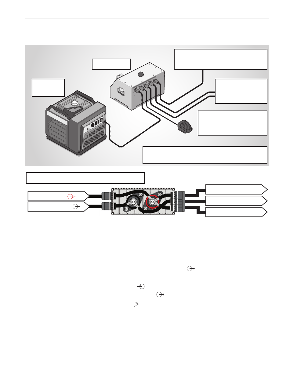
GENERATOR
To cathode array/boom inter-
connect box or hull ground
To Anode
arrays/boom in-
terconnect box
Remote foot-switch or
boat’s internal foot-
switch connection
APEX unit
Power
source
Basic Hookup Diagram
Instructions
The instructions below will work
with most boats and also some
shore electrofishing applications.
1. Connect APEX to generator
power source by hooking up the
generator’s output connector to
the APEX’s Power In connector
2. Connect remote foot switch to
APEX’s Foot Switch connector .
You can also connect the APEX’s
foot switch connector to a boat’s
internal foot switch system, if
so equipped. Consult technical
support if further guidance is
needed.
3. Connect one or both Anode
Connectors to anode arrays or
boom-mounted anode arrays via
the APEX’s Anode connectors 1
and/or 2 .
4. Connect the cathode array to the
APEX via the Cathode connector
. You can also, in some configu-
rations, use the boat’s hull as the
cathode.
Consult your boat’s specifications
or Smith-Root technical support for
more information.
APEX Boat Hookup
Hook up using Boom Interconnect Box
APEX Anode
Boom Anode
Boom Anode
Boat Ground
APEX Cathode

5
APEX BOAT ELECTROFISHER
www.smith-root.com
APEX Boat Electrofisher Quick-Start Guide
1. External Components
i. Electrode cables – Connect the electrically positive anode and neg-
ative cathode of the electric system.
a. Anode – Positive electrode(s) that extend from bow of boat.
b. Cathode – Negative electrode that is often the aluminum hull
and/or a bow-mounted cathode dropper array.
ii. Foot Switch - Connects to the foot switch that allows the user to
easily activate and deactivate the electrical output.
iii.Power Source - Connects to the generator that powers the APEX
control box.
2. Powering up and down
i. Circuit Breaker
a. Turn on - Push the circuit breaker in the UP position.
b. Turn off - Push the circuit breaker in the DOWN position
ii. Emergency Stop Button – Red button on the control panel of the
APEX with yellow protective shroud.
a. Turn on - Twist and lift the red button to activate the APEX. A
short tone will emit from the unit and then the red light will acti-
vate for duration of the startup time (about 8 seconds).
b. Turn off – Push down on the red button.
3. Electrical Settings
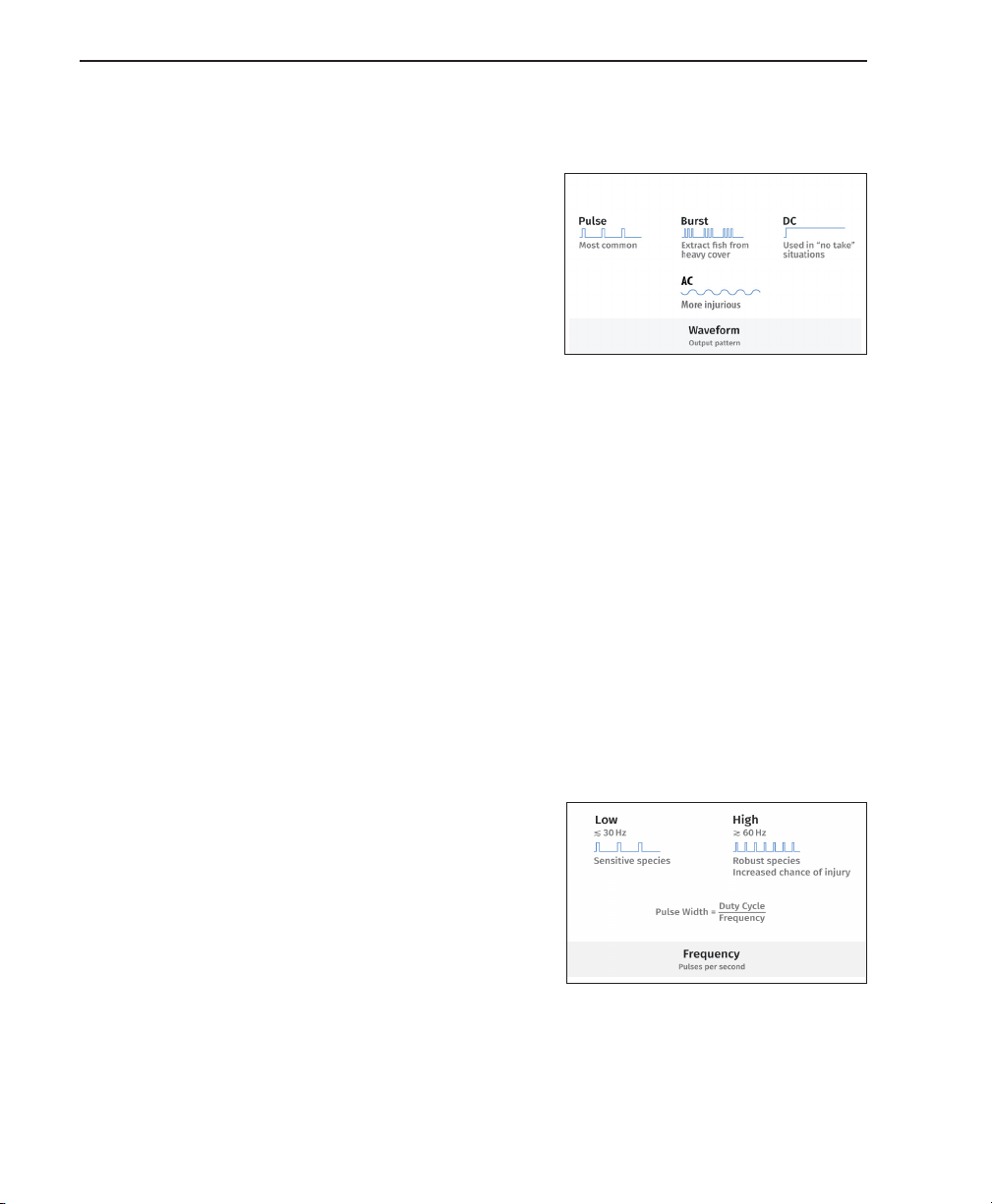
i. Waveform – Determines the shape of the electrical output. From
home screen, press WAVEFORM button and use blue hotkey but-
tons ·to select a waveform. Press FAVORITES button to store and
recall settings. Press HELP button for a description of each wave-
WARNING! LIVE ELECTRICAL EQUIPMENT WHEN ENERGIZED.
DIRECT CONTACT WITH EQUIPMENT MAY CAUSE ELECTRIC
SHOCK OR BURN. Appropriate personal protective equipment
is required at all times. Using this equipment in a manner not advised
in the instruction manual, quick start guide, tutorial video(s) or
otherwise could result in injury, death, or damage to the unit. Users
should notify bystanders of the equipment’s use and function before
and during operation. If conditions become unsafe, cease using the
equipment immediately. While electrofishing, it is strongly advised
to wear electrically rated lineman gloves, insulated footwear, and a
Personal Flotation Device (PFD).
6
QUICK-START GUIDE
2019
form. Once complete, press BACK
button to return to home screen.
a. Direct Current (DC) – Continu-
ous, uninterrupted current flows
from APEX between anode and
cathode. This method is generally
favored for use with endangered
and threatened species.
DC does create a higher power
demand from the generator.
b. Pulsed - Pulsed Direct Current (PDC) is pulsed at a user-defined
frequency and duty cycle. This is the most commonly used elec-
trofishing waveform because of its balance of moderate power
use, increased capture efficiency over DC, and decreased injury
potential over AC.
c. Burst – Current is pulsed in packets of bursts with defined gaps
of electrical output between bursts. This waveform is commonly
used to remove fish from heavy cover or juvenile lamprey from
sediments.
d. Alternating Current (AC) - Current reverses polarity on the fre-
quency of the output from the generator (only available up to
347 volts RMS). This waveform is uncommonly used with the
exception of eradication studies or on the extremes of water
conductivity.
ii. Frequency – Determines the rate of
electrical pulsing. To modify frequen-
cy, press FREQUENCY button, then
use arrows to increase and decrease
values. Press HELP button for a de-
scription of Frequency. Once com-
plete, press BACK button to return to
home screen.
a. 7.5 – 15 Hertz – Low frequency is
commonly used with Pulsed Di-
rect Current Waveform to capture catfish and other electrically
sensitive bottom dwelling fish. Fish are often active, requiring
active netting.
Screenshot: Waveform types
Screenshot: Frequency

7
APEX BOAT ELECTROFISHER
www.smith-root.com
b. 30 Hertz – Moderate frequency is commonly used for more frag-
ile species with increased vertebral count and minimized scales.
c. 60 hertz – Higher frequency is commonly used for more robust
species with decreased vertebral count and thicker scaling.
d. > 60 Hertz - Generally avoided because of increased risk of injury.
iii. Duty Cycle – Determines the percent-
age of time that the APEX is applying
power every cycle. To modify Duty
Cycle, press DUTY CYCLE button, then
use arrows to increase and decrease
values. Press HELP for a descrip-
tion of Duty Cycle. Once complete,
press BACK button to return to home
screen.
a. 12-15% - A minimal duty cycle
percentage that maintains very short widths for each electrical
pulse. Similar to low frequency, this is commonly used for more
fragile species with increased vertebral count and minimized
scales.
b. 20-40% (~30%) – A duty percentage commonly used for more
robust species with decreased vertebral count and thicker scal-
ing.
iv. Voltage – Determines the amplitude
of the electrical potential. The voltage
should be set according to environ-
mental conditions, especially ambient
water conductivity. To modify voltage,
press VOLTAGE button, then use ar-
rows to increase and decrease values.
Once complete, press BACK button to
return to home screen.
a. 500 – 1,200 Volts – High voltage is used in very low ambient con-
ductivity water. Additionally, higher voltages are often useful in
deep and wide pools.
b. 150 – 500 Volts – Moderate voltage is typically used in moderate
ambient conductivity waters.
Screenshot: Duty Cycle
Screenshot: Voltage

8
QUICK-START GUIDE
2019
c. 50 – 150 Volts – Low voltage is typically used in high conductivity
water. Additionally, lower voltage is often useful in shallower pools.
4. Favorites
i. Saving Electrical Inputs – To save an
electrical input to the Favorites sec-
tion, press the WAVEFORM button on
the home screen, then press FAVOR-
ITES. Finally, press the + button to
save the active input settings.
ii. Recalling Electrical Inputs - To ac-
tivate an electrical input previously
saved in the Favorites section, press
the WAVEFORM button on the home
screen, then press FAVORITES. Press the button associated with
the previously saved input settings of choice and then press the
USE ✓button.
5. Effort
i. Timer/Alarm
a. Timer – The timer counts the number of seconds the output
was activated since the timer was last reset. To reset the tim-
er, Press the TIMER button, then press RESET. Once complete,
press BACK button to return to home screen.
b. Alarm – An alarm can be set at 60 second intervals to inform
the user that a defined amount of effort has elapsed. A re-
minder alarm will subsequently activate every 60 seconds of
effort beyond the alarm. Therefore, it can be helpful to set the
alarm for 60 seconds less than the intended effort as a meth-
od of warning the user of the upcoming end of effort. To set
the Alarm, press the TIMER button, then press ALARM and use
arrows to increase and decrease the number of seconds. Once
complete, press BACK button to return to home screen. A ton-
al alarm will activate once the noted amount of electrofishing
effort elapses. A reminder alarm will continue to occur every
60 seconds after the alarm is triggered until the timer is reset.
Screenshot: Favorites

9
APEX BOAT ELECTROFISHER
www.smith-root.com
6. In Field Help
i. Light Bulbs – Light bulb icons can be accessed on the APEX for
further information on particular topics.
ii. Diagnostic Screen – A diagnostic screen can be found in the menu
that displays a multitude of input and output parameters along with
system information. Press Menu, then Device Information, then
Diagnostics.
7. Menu
i. Display Mode - Allows user to modify display for different light-
ing conditions.
a. Light - Bright background
b. Dark - Dark background
c. Dual Channels – Allows the user to define and activate two
different electrical outputs by releasing and pressing the foot
switch in less than one second
d. Activated – A single electrical output is set on the main screen.
ii. Deactivated – Two electrical outputs, a primary and a secondary,
are set on the main screen. This is commonly used when a sensitive
setting is used in the primary output slot and a more aggressive
output is used in the secondary to allow fish to escape heavy cover
then be properly incapacitated. The primary output is activated by
pressing the foot switch and the secondary output is activated by
releasing and pressing the foot switch in less than one second. If
you do not press the pedal within one second of release, the prima-
ry output will be activated.
iii.Device Information – Displays information about the manufacturing,
service, and operation of the APEX electrofisher.
a. Reset – Resets the Apex APEX to default settings.
b.Diagnostics – Displays information about the performance of the
APEX electrofisher.
10
QUICK-START GUIDE
2019
7. Input and Output Data Storage
i. Data Storage – The APEX stores input
and output data every second that the
anode pole switch is activated.
a. Recording data – The APEX automat-
ically records data when the output is
active.
b. Viewing Data – The home screen
displays real time electrical input
values, peak electrical output values,
GPS location (when signal is avail-
able), battery meter, timer/alarm, and
real-time graphs. Real-time graphs
actively display the previous 3 min-
utes of peak output electrical settings
as well as all faults/errors/warnings.
Along the bottom of the home screen
is a display of one second of input
variables in graphical format that ani-
mates when the anode pole switch is
activated.
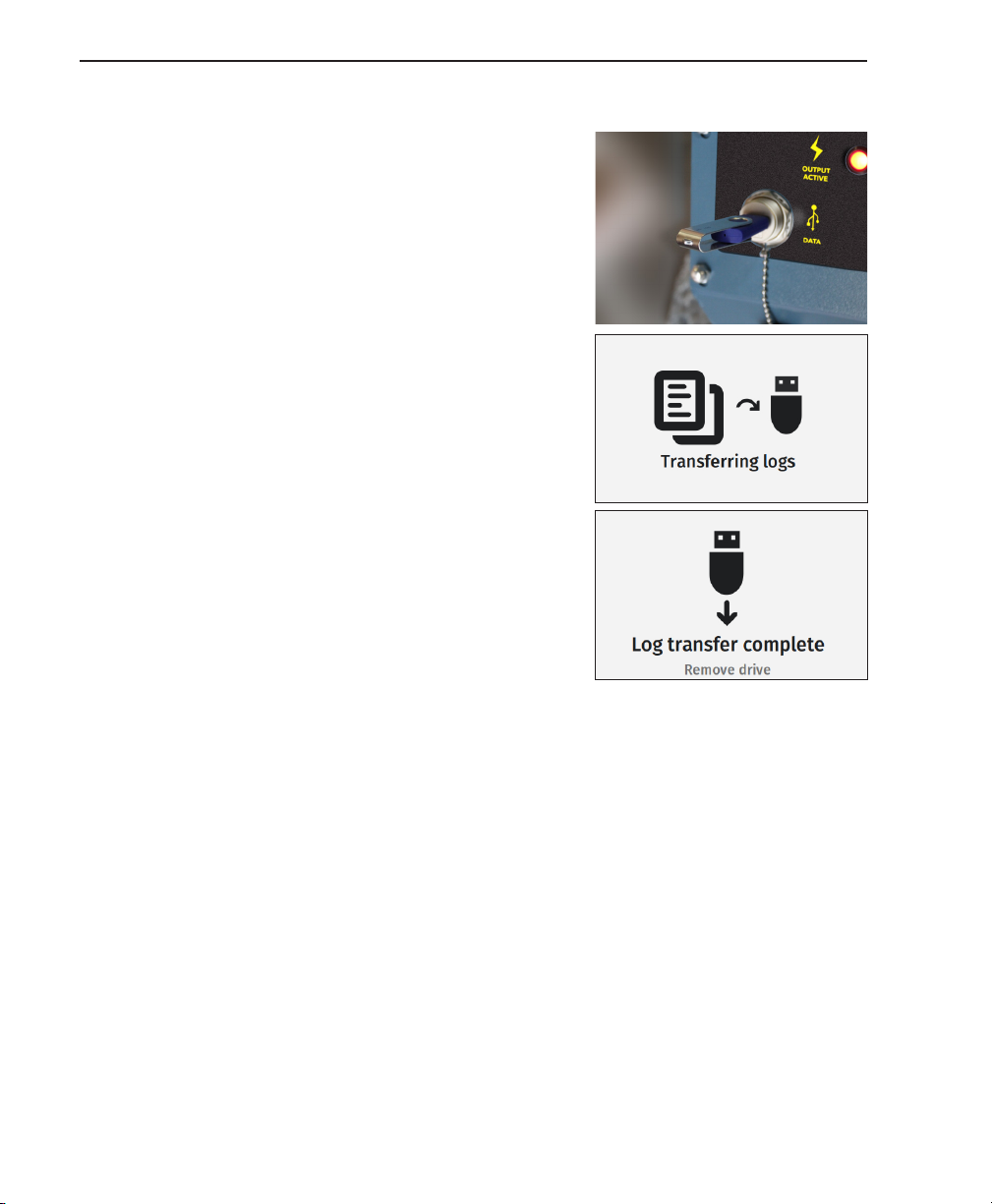
c. Downloading data – Unscrew the dust
and water cap from the USB port
on the front panel of the APEX and insert a USB flash drive. All
stored data on the APEX will load onto the USB flash drive as a
.csv file that can be opened in a spreadsheet program (i.e. Micro-
soft Excel). Follow onscreen prompts to remove USB flash drive.
Place cap back on APEX after transferring data.
8. Safety
i. Sound – A tonal alert makes a tone when the APEX is first turned
on, when an error/fault/warning occurs, and when the foot switch
is activated. Tonal rate is continuously related to the average pow-
er being put into the water. A lower rate (~1 tone per second) indi-
cates lower power and a high rate (~4 tones per second) indicates
higher power. The volume can be controlled by rotating the bezel
on the tonal alert.
ii. LED light - Lights on the face of the APEX activate when the APEX
is first turned on in sync with sound, when an error/fault/warning
occurs, and when the foot switch is activated. In noisy situations,
this safety feature proves valuable.

11
APEX BOAT ELECTROFISHER
www.smith-root.com
TECHNICAL SPECIFICATIONS
Input Power: 240VAC 50/60hz
Conductivity Range: 25-5000uS
Output Waveforms: DC, Pulsed DC, Burst of Pulses DC, AC
Output Voltage: 0-1350VDC - 0-240VAC
Voltage Adjustment Increment: 1V
Output Current: 0-22ADC continuous @ 300VDC
Peak Output Current: 55A @ 250V 30Hz 10% duty cycle 30A @
240VAC
Output Power: 7200W continuous
Peak Output Power: 18,000W
Output Frequency Range: 1-1000hz
Frequency Adjustment Increment: 1hz
Duty Cycle Range: 1-100%
Duty Cycle Adjustment Increment: 1%
Power Limit Range: 25-7200W average power
Power Limit Adjustment Increment: 25W
Timer: 999,999 seconds standard
Alarm: 1-3600 seconds countdown or count up mode
with alarm at end of count
Data logging: Automatically logs Output: Peak and Average
Voltage, Current, Power, Waveform, GPS posi-
tion, Time stamp every second
Generator: 8000W continuous for max. output. 240V @
30A 50/60Hz. Floating neutral
Dimensions: W: 21 X D: 17.5 X H: 13.75 (W: 53.3 cm X D: 44.4
cm X W: 35 cm)
Weight: 47.2 lbs (21.4 kg)

info@smith-root.com
(360) 573-0202
Vancouver, WA USA
www.smith-root.com
S
i
n
c
e
1
9
6
4
Table of contents
Other Smith-Root Fishing Equipment manuals

Smith-Root
Smith-Root 15B User manual

Smith-Root
Smith-Root Electric Fish Handling Gloves User manual

Smith-Root
Smith-Root VVP-15C User manual

Smith-Root
Smith-Root VVP-15B User manual

Smith-Root
Smith-Root 12 User manual

Smith-Root
Smith-Root GPP 2.5 User manual

Smith-Root
Smith-Root PES User manual

Smith-Root
Smith-Root LR-24 User manual
Popular Fishing Equipment manuals by other brands


Avet Reels
Avet Reels Two Speed Assembly SX 6 - 4 parts list

Baitstar
Baitstar Pro-X user manual

Angling Technics
Angling Technics Microcat MkII operating instructions

Ardent
Ardent C Series owner's manual

Garmin
Garmin PORTABLE ICE FISHING KIT installation instructions

Akva
Akva Polarcirkel 685 owner's manual


