Smithy Midas 1220 XL User manual

MIDAS 1220 XL
COMBINATION LATHE/MILL/DRILL
OPERATOR’S MANUAL
Updated August, 2008
170 Aprill Dr., Ann Arbor, MI, USA 48103
Toll Free 1-800-476-4849
www.smithy.com

©2008 Smithy Co. All rights reserved (Revision 1).
170 Aprill Dr., Ann Arbor, Michigan, USA 48103
Toll Free Hotline: 1-800-476-4849
Fax: 1-800-431-8892
International: 734-913-6700
International Fax: 734-913-6663
All images shown are from Midas 1220 XL machine.
All rights reserved. No part of this manual may be reproduced or transmitted in any form
by any means, electronic, mechanical, photocopying, recording, or otherwise,
without prior written permission of Smithy Co. For information on getting permission for
While every precaution has been taken in the preparation of this manual, Smithy Co. shall not
have any liability to any person or entity with respect to any loss or damage caused or
alleged to be caused directly or indirectly by the instructions contained in this manual.
Please see section on warranty and safety precautions before operating the machine.
Printed and bound in the United States of America.

Table of Contents
Inventory Check List ............................................i-iv
Chapter 1: Introduction .........................................1-1
Chapter 2: Safety ................................................2-1
Chapter 3: Knowing Your Machine ............................3-1
Chapter 4: Caring For Your Machine .........................4-1
Chapter 5: Basic Parts of the MI-1220 XL ..................5-1
Chapter 6: Uncrating and Setting Up the MI-1220 XL
Moving the machine . . . . . . . . . . . . . . . . . . . . . . . . . . . . . . . . . . . . . . .6-1
Uncrating and Positioning the machine . . . . . . . . . . . . . . . . . . . . . .6-1
Millhead . . . . . . . . . . . . . . . . . . . . . . . . . . . . . . . . . . . . . . . . . . . . . . . . . .6-2
Tailstock . . . . . . . . . . . . . . . . . . . . . . . . . . . . . . . . . . . . . . . . . . . . . . . . .6-2
Three Jaw Chuck . . . . . . . . . . . . . . . . . . . . . . . . . . . . . . . . . . . . . . . . . .6-2
Selecting Location . . . . . . . . . . . . . . . . . . . . . . . . . . . . . . . . . . . . . . . . .6-4
Cleaning and Lubricating the MI-1220 LTD . . . . . . . . . . . . . . . . . . . .6-4
Oiling the Headstock . . . . . . . . . . . . . . . . . . . . . . . . . . . . . . . .6-5
Oiling the Ways . . . . . . . . . . . . . . . . . . . . . . . . . . . . . . . . . . . . .6-5
Oiling the Carraige . . . . . . . . . . . . . . . . . . . . . . . . . . . . . . . . . .6-5
Oiling the Tailstock . . . . . . . . . . . . . . . . . . . . . . . . . . . . . . . . . .6-6
Oiling the Apron . . . . . . . . . . . . . . . . . . . . . . . . . . . . . . . . . . . .6-6
Oiling the Leadscrew . . . . . . . . . . . . . . . . . . . . . . . . . . . . . . . .6-7
Oiling the Compound Angle Toolpost . . . . . . . . . . . . . . . . . .6-7
Setting Up Your MI-1220 XL . . . . . . . . . . . . . . . . . . . . . . . . . . . . . . . . .6-8
Setting Lathe and Mill Speeds . . . . . . . . . . . . . . . . . . . . . . . . . . . . . .6-8
Adjusting Belt Tension . . . . . . . . . . . . . . . . . . . . . . . . . . . . . . . . . . . . .6-9
Adjusting Gibs . . . . . . . . . . . . . . . . . . . . . . . . . . . . . . . . . . . . . . . . . . .6-10
Reducing Backlash . . . . . . . . . . . . . . . . . . . . . . . . . . . . . . . . . . . . . . .6-11
Crossfeed . . . . . . . . . . . . . . . . . . . . . . . . . . . . . . . . . . . . . . . . . . . . . . .6-11
Longfeed . . . . . . . . . . . . . . . . . . . . . . . . . . . . . . . . . . . . . . . . . . . . . . . .6-12
Running in the MI-1220 XL . . . . . . . . . . . . . . . . . . . . . . . . . . . . . . . . .6-12
Chapter 7: Turning
Turing Speeds . . . . . . . . . . . . . . . . . . . . . . . . . . . . . . . . . . . . . . . . . . . .7-2
Gear Ratios . . . . . . . . . . . . . . . . . . . . . . . . . . . . . . . . . . . . . . . . . . . . . . .7-3

Chapter 8: Metalcutting Theory
Tool Sharpness . . . . . . . . . . . . . . . . . . . . . . . . . . . . . . . . . . . . . . . . . . .8-2
Heat . . . . . . . . . . . . . . . . . . . . . . . . . . . . . . . . . . . . . . . . . . . . . . . . . . .8-3
Chapter 9: Grinding Cutter Bits for Lathe Tools
High Speed Steel Cutters . . . . . . . . . . . . . . . . . . . . . . . . . . . . . . . . . . .9-1
Materials Other than Steel . . . . . . . . . . . . . . . . . . . . . . . . . . . . . . . . . .9-3
Bits for Turning and Machining Brass . . . . . . . . . . . . . . . . . . . . . . . .9-4
Special Chip Craters and Chipbreakers . . . . . . . . . . . . . . . . . . . . . . .9-4
Using a Center Gauge to Check V-Thread Forms . . . . . . . . . . . . . .9-4
Acme or Other Special Threads . . . . . . . . . . . . . . . . . . . . . . . . . . . . .9-5
Carbide-Tipped Cutters and Cutter Forms . . . . . . . . . . . . . . . . . . . . .9-5
Chapter 10: Setting Up Lathe Tools
Cutting Tool Height . . . . . . . . . . . . . . . . . . . . . . . . . . . . . . . . . . . . . . .10-1
Turning Tools . . . . . . . . . . . . . . . . . . . . . . . . . . . . . . . . . . . . . . . . . . . .10-1
Threading Tools . . . . . . . . . . . . . . . . . . . . . . . . . . . . . . . . . . . . . . . . . .10-2
Cutoff, Thread Cutting and Facing Tools . . . . . . . . . . . . . . . . . . . . .10-3
Boring and Inside Threading Tools . . . . . . . . . . . . . . . . . . . . . . . . .10-3
Chapter 11: Setting Up with Centers, Collets and Chucks
Centering . . . . . . . . . . . . . . . . . . . . . . . . . . . . . . . . . . . . . . . . . . . . . . . .11-1
Centering a Round and Rectangular Steels . . . . . . . . . . . . . . . . . .11-2
Mounting Work between Centers . . . . . . . . . . . . . . . . . . . . . . . . . .11-4
Using a Clamp Dog . . . . . . . . . . . . . . . . . . . . . . . . . . . . . . . . . . . . . . .11-4
Setting Up Work on Mandrel . . . . . . . . . . . . . . . . . . . . . . . . . . . . . . .11-6
Steady Rest and Follow Rest . . . . . . . . . . . . . . . . . . . . . . . . . . . . . . .11-6
Setting Up Work in a Chuck . . . . . . . . . . . . . . . . . . . . . . . . . . . . . . . .11-8
Mounting Work in a Four-Jaw Independent
Lathe Chuck . . . . . . . . . . . . . . . . . . . . . . . . . . . . . . . . . . . . . . .11-8
Mouting Work in a Three-Jaw Universal Chuck . . . . . .11-10
Collet and Collet Attachements . . . . . . . . . . . . . . . . . . . . . . . . . . . .11-11
Toolpost Grinders . . . . . . . . . . . . . . . . . . . . . . . . . . . . . . . . . . . . . . .11-12
Chapter 12: Lathe Turning
Rough Turning . . . . . . . . . . . . . . . . . . . . . . . . . . . . . . . . . . . . . . . . . . .12-1
Finish Turning . . . . . . . . . . . . . . . . . . . . . . . . . . . . . . . . . . . . . . . . . . . .12-2
Turning to Shapes . . . . . . . . . . . . . . . . . . . . . . . . . . . . . . . . . . . . . . . .12-2
Machining Square Corners . . . . . . . . . . . . . . . . . . . . . . . . . . . . . . . .12-3
Taper Turning . . . . . . . . . . . . . . . . . . . . . . . . . . . . . . . . . . . . . . . . . . . .12-4
Boring a Tapered Hole . . . . . . . . . . . . . . . . . . . . . . . . . . . . . . . . . . . .12-6

Chapter 13: Lathe Facing and Knurling
Facing Across the Clutch . . . . . . . . . . . . . . . . . . . . . . . . . . . . . . . . . .13-1
Knurling . . . . . . . . . . . . . . . . . . . . . . . . . . . . . . . . . . . . . . . . . . . . . . . . .13-2
Chapter 14: Changing Gears ..................................14-1
Chapter 15: Cutting Screw Threads
Threading Terms . . . . . . . . . . . . . . . . . . . . . . . . . . . . . . . . . . . . . . . . .15-1
Cutting Right Hand Threads . . . . . . . . . . . . . . . . . . . . . . . . . . . . . . . .15-3
Cutting Left Hand Threads . . . . . . . . . . . . . . . . . . . . . . . . . . . . . . . . .15-4
Cutting Multiple Threads . . . . . . . . . . . . . . . . . . . . . . . . . . . . . . . . . .15-4
What Not To Do When Cutting Threads . . . . . . . . . . . . . . . . . . . . .15-5
Finishing Off a Threaded End . . . . . . . . . . . . . . . . . . . . . . . . . . . . . . .15-5
Cutting Threads on a Taper . . . . . . . . . . . . . . . . . . . . . . . . . . . . . . . .15-5
Chapter 16: Lathe Drilling and Boring
Reaming . . . . . . . . . . . . . . . . . . . . . . . . . . . . . . . . . . . . . . . . . . . . . . . . .16-1
Boring . . . . . . . . . . . . . . . . . . . . . . . . . . . . . . . . . . . . . . . . . . . . . . . . . .16-2
Cutting Internal Threads . . . . . . . . . . . . . . . . . . . . . . . . . . . . . . . . . . .16-4
Cutting Special Form Internal Threads . . . . . . . . . . . . . . . . . . . . . .16-5
Chapter 17: Cutting Off or Parting with a Lathe .........17-1
Chapter 18: Milling .............................................18-1
Chapter 19: Workholding
Mounting to the Table . . . . . . . . . . . . . . . . . . . . . . . . . . . . . . . . . . . . .19-1
Using a Vise . . . . . . . . . . . . . . . . . . . . . . . . . . . . . . . . . . . . . . . . . . . . .19-1
Dividing Heads . . . . . . . . . . . . . . . . . . . . . . . . . . . . . . . . . . . . . . . . . . .19-2
Rotary Tables . . . . . . . . . . . . . . . . . . . . . . . . . . . . . . . . . . . . . . . . . . . .19-2
Chapter 20: Holding Milling Cutters
Arbors . . . . . . . . . . . . . . . . . . . . . . . . . . . . . . . . . . . . . . . . . . . . . . . . . .20-1
Collets and Holders . . . . . . . . . . . . . . . . . . . . . . . . . . . . . . . . . . . . . . .20-1
Adaptors . . . . . . . . . . . . . . . . . . . . . . . . . . . . . . . . . . . . . . . . . . . . . . . .20-2
Chapter 21: Milling Cutters
End Mill Cutters . . . . . . . . . . . . . . . . . . . . . . . . . . . . . . . . . . . . . . . . . .21-1
Plain Milling Cutters . . . . . . . . . . . . . . . . . . . . . . . . . . . . . . . . . . . . . .21-3
Side Milling Cutters . . . . . . . . . . . . . . . . . . . . . . . . . . . . . . . . . . . . . . .21-3

Inventory Check List
It is a good idea to take inventory of the parts of your machine soon after it is unpacked.
By doing so, you can quickly determine if any parts are missing. In addition, should you
find it necessary to return the machine to Smithy for any reason, the inventory will ensure
that all the parts you received have been returned. It is also good to take a look at the
inventory before you operate the machine so that you can be familiar with the names of
all the parts of your Smithy machine.
qAllen Wrench, 4mm
Item #: C30540
Quantity 1
qAllen Wrench, 5mm
Item #: C30542
Quantity 1
qAllen Wrench, 6mm
Item #: C30537
Quantity 1
qAllen Wrench, 8mm
Item #: C30536
Quantity 1
qWrench, 14 mm
Item #: 81-500
Quantity 1
qArbor
, JT33-MT3
(No Tang)
Item #: C30523
Quantity 1
qDrift, MT2
Item #: C30558
Quantity 1
qDead Center, MT3
Item #: 41-003
Quantity 1
qDead Center, MT4
Item #: 41-004
Quantity 1
qDrill chuck, 1/2”
Item #: 72-001
Quantity 1
qGear, 32 Teeth
Item #: C30145
Quantity 2
qGear, 33 Teeth
Item #: C30146
Quantity 1
qGear
,39 Teeth
Item #: C30148
Quantity 1
qGear
,40 Teeth
Item #: C30149
Quantity 1
i
Or Visit www.smithy.com
qGear, 42 Teeth
Item #: C30150
Quantity 1
qGear, 45 Teeth
Item #: C30156
Quantity 1
qGear, 48 Teeth
Item #: C30151
Quantity 1
qGear, 49 Teeth
Item #: C30152
Quantity 1
qGear, 50 Teeth
Item #: C30153
Quantity 1
qGear, 56 Teeth
Item #: C30157
Quantity 1
qGear, 60 Teeth
Item #: C30159
Quantity 1
qGear, 70 Teeth
Item #: C30202
Quantity 1
Gears on the machine:
qGear, 27 Teeth
Item #: C30143
Quantity 2
qGear, 30 Teeth
Item #: C30144
Quantity 1
qGear, 60 Teeth
Item #: C30159
Quantity 1
qGear, 63 Teeth
Item #: C30160
Quantity 1
qJaws (3), 5”
Item #: 9-10
Quantity 1 set of 3
qKey, Lathe Chuck
Item #: C30532
Quantity 1
qKey, Drill Chuck
Item #: C30533
Quantity 1
qOpen End Wrench,
8/10mm
Item #: C30539
Quantity 1
qOpen End Wrench,
17/19mm
Item #: C30535
Quantity 1
qAdapter Precision
End Mill
Item #: 65-010
Quantity 1
qEnd Mill Single
4FHSS3/8 1/4”
Item #: 50-402
Quantity 1
Midas 1220 XL Operator’s Manual
ii For Assistance: Call Toll Free 1-800-476-4849

qEnd Mill Single
4 FHSS 3/8 3/8”
Item #: 50-406
Quantity 1
qEnd Mill Single
4 FHSS 3/8 1/4”
Item #: 50-410
Quantity 1
qT-Slot Nut, 7/16”
Item #: 35-105
Quantity 2
qAir Mask
Item #: 15-020
Quantity 1
qGoggles
Item #: 15-015
Quantity 1
qEar Plug
Item #: 15-025
Quantity 1
qDrawbar
,
3/8 x 16 x 14”
Item #: 75-A
Quantity 1
qNut, 3/8 16
Item #: 7-6
Quantity 1
qWasher,
Flat 5/16”
Item #: 7-8
Quantity 1
qWasher,
Anti-Back Lash Shim
Item #: 82-050
Quantity 3
qVise, Bracket Bolt
3/8 x 1-1/4”
Item #: 36-610
Quantity 2
qPlug, Drill Chuck Arbor
Item #: S12898
Quantity 1
qVise, 0-90 Degrees
Adjustable Angle 3-1/4” Jaw
Item #: 32-110
Quantity 1
qCarbide Bit Set
Item #: 43-000
Quantity 1
qMachine Tool
Basics (DVD)
Item #: 12-004
Quantity 1
qCutting Fluid/ Tapping
Item #: 49-101
Quantity 1
Inventory Checklist
iii
Or Visit www.smithy.com

qOperator’s Manual
Item #: 83-949
Quantity 1
qManual Cover
Item #: 83-942
Quantity 1
qOil Can
Part # 80-100
Quantity 1
q5”3Jaw Chuck
Part # C30532
Quantity 1
qCompound
Angle Toolpost
Part # 45-110
Quantity 1
Missing Items?
If you find that an item is missing or defective from your Quick Start Tool Pack
Call Us TOLL FREE 1-800-476-4849
or send an e-mail to info@smithy.com
within 30 days of receiving your machine so that we may assist you immediately.
Our sales and service technicians are available 8am to 5pm ET, Mondays to Fridays.
iv For Assistance: Call Toll Free 1-800-476-4849
Midas 1220 XL Operator’s Manual

Chapter 1
Introduction
Congratulations on purchasing a Smithy Midas 1220 XL lathe-mill-drill. We are pleased
you chose Smithy to fulfil your machining needs.
The purpose of this manual is to give the machinist, beginniner or advanced, the
information he needs to operate the Smithy Midas 1220 XL. It will teach you about the
machine's parts and how to care for them. In fact, education is our primary goal. We'll
explain how to grind cutters, set up lathe tools, hold workpieces, and do all basic
machining operations.
Please read this operator's manual carefully. If you don't understand how your machine
works, you may damage it, your project, or yourself. If you want to learn more about
machining practices, Smithy offers books that meet the needs of machinists at all level of
experience. We also suggest using your local library as a resource. Enrolling in a
machining class will give you the best knowledge of machining.
If you have any questions not covered in this operator's manual, please call Smithy Co.
Our trained technicians will help you with any machining problems you may have. You
can reach them by dialing 1-800-476-4849 Monday through Friday, 8:00 am to 5:00 pm
Eastern time.
We are always interested in your suggestions to improve our products and services. Feel
free to contact us by phone or in writing. If you have comments about this operator's
manual, or if you have a project you'd like to share with other Smithy owners, contact the
Communications Director
, Smithy Co., PO Box 1517, Ann Arbor, MI48106-1517.
We look forward to a long working relationship with you. And thank you again for putting
your trust in Smithy.
Customer Information
This manual should remain with your Smithy machine. If ownership changes, please
include the owner's manual with the machine.
Model # ________________________________________
Serial #_________________________________________
(on the back of the lathe bed)
Purchase date ___________________________________
Delivery date ____________________________________
Sales Technician__________________________________
1-1
Or Visit www.smithy.com

Chapter 2
Safety
Your workshop is only as safe as you make it. Take responsibility for the safety of all who
use or visit it. This list of rules is by no means complete, and remembers that common
sense is a must.
1. Know your machine. Read this manual thoroughly before attempting to operate your
lathe-mill-drill. Don't try to do more than you or your machine can handle. Understand
the hazards of operating a machine tool. In particular, remember never to change speeds
or setups until the machine is completely stopped, and never to operate it without first
rolling up your sleeves or tying them at your wrists.
2. Ground the machine. The Midas 1220 XL has a three conductor cord and a three
pronged grounding type receptacle. Never connect the power supply without properly
grounding the machine.
3. Remove all adjusting keys and wrenches from the machine before operating. A chuck
key or misplaced Allen wrench can be a safety hazard.
4. Keep your work area clean and organized. Cluttered work areas and benches invite
accidents. Have a place for everything and put everything in its place.
5. Keep children away from the machine while it is in use. Childproof your shop with
padlocks, master switches, and starter keys, or store the machine where children do not
have access to it.
6. Wear appropriate clothing. Avoid loose fitting clothes, gloves, neckties, or jewellery
that could get caught in moving parts. If you have long hair, tie it up or otherwise keep
it out of the machine.
7. Use safetyglasses, goggles, or a face shield at all times. Use glasses designed for
machinery operation; regular glasses will not do. Have extras for visitors. Know when to
wear a face mask and earplugs, as well.
8. Check for damaged parts. Make sure the machine will run properly before operating it.
9. Disconnect the machine before servicing and when changing accessories. Shut power
off before making changes, removing debris, or measuring your work. Don't reach over
the machine when it's operating. Keep you hands out of the way.
10. Avoid accidental starts. Turn the switch to Off before plugging in the machine.
11.Secure your work. Flying metal is dangerous. Loose work can also bind tools.
12. Use the recommended accessories. Understand how to use them beforetrying them
out.
2-1 For Assistance: Call Toll Free 1-800-476-4849

13. Use the correct tool for the job. Don't try to make a tool into something it isn't.
14. Keep your mind on your work.
Pay attention to these simple rules and you will spend many safe, enjoyable hours in your
workshop.
Remember: Your safety largely on your practices. Modifying your machine may void the
warranty and create potential hazards.
Safety
2-2
Or Visit www.smithy.com

Chapter 3
Knowing Your Machine
The Midas 1220 XL has a 3/4 hp, 110 V motor. The motor powers the lathe and millhead
through the main belt drive and the mill/drill belt drive.
Apositive lock clutch in front of the spindle pulley transfers power to either the lathe or
the mill. The clutch has three positions. To power the lathe, pull the clutch handle out. To
power the mill, push the clutch all the way in. The middle position is neutral. Always shift
the clutch with the motor turned off.
The Smithy can use V-belts or round polyurethane belts. The latter produce less dust and
is easier to change than standard V-belts.
The lathe runs at six speeds from 160 to 1600 rpm. To change lathe speeds, adjust the
belts in the main belt-drive system. This system uses three pulleys: the motor pulley,
floating idler pulley and spindle pulley.
To run the lathe at lower turning speeds, use two belts. Install one between the motor
and idler pulleys and the other between the idler and spindle pulleys. To increase the
speed, move the spindle belt in two more positions on the pulleys.
For higher ranges, use one long belt from the motor pulley directly to the spindle pulley.
You can adjust this belt to three different positions on the pulleys.
The millhead also has a belt-drive system. It uses only one belt, adjustable to either the
top or bottom position on the pulleys. These two positions, in conjunction with the main
belt drive, let you select 12 speeds ranging from 125 to 1600 rpm for milling or drilling.
3-1 For Assistance: Call Toll Free 1-800-476-4849

Chapter 4
Caring For Your Machine
The Midas 1220 XL is a delicate, precision tool with ground ways and hand-scraped
bearing surfaces under the table and carriage. Any rust spot or battering of the ways, any
chips or grit between close fitting parts, will affect the accuracy of this fine tool. Follow
these guidelines whenever you use your Smithy machine.
When you finish working, wipe machined surfaces with a clean, oily rag. Never leave the
machine without this thin film of protective oil over all parts that might rust, especially
ground finished parts.
Never lay wrenches, cutting tools, files, or other tools across the ways of your lathe. The
slightest dent or burr could impair its accuracy.
Before inserting collars, centers, adapters, or drawbar attachments in either the spindle
or tailstock spindle, wipe them with a clean, oily rag. Also wipe all internal surfaces
carefully with an oily rag on a ramrod. Chips or dirt on the centers or in the spindle nose
can scratch or mar surfaces and interfere with the assembled part's alignment.
Lubricate the machine beforeeach use (see Section 6.4)
4-1
Or Visit www.smithy.com
Chapter 5
Basic Parts of the MI-1220 XL
To learn the operations of your machine, you have to know the names and functions of
its basic parts.
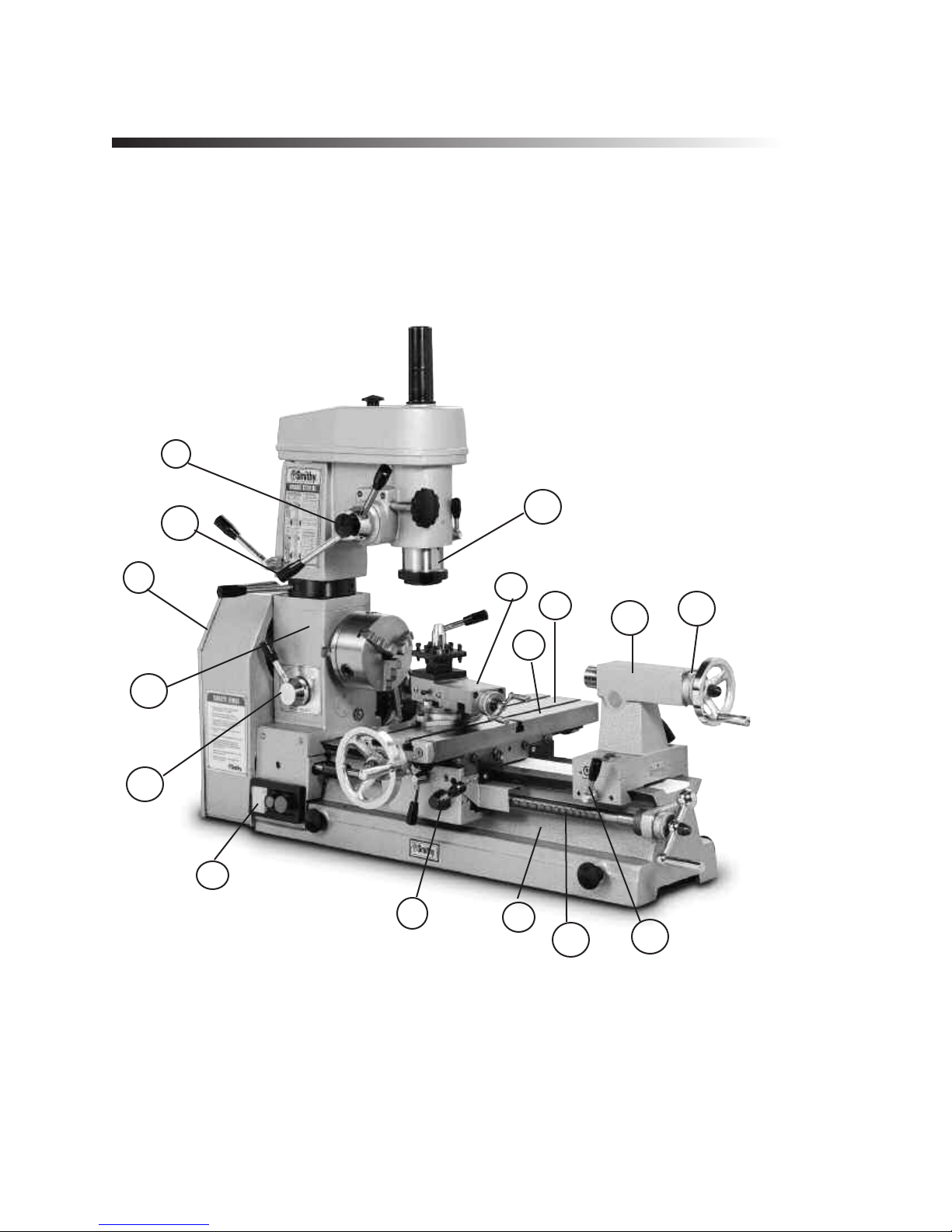
Figure 5.1 Basic parts of the MI-1220 XL
1.
Bed
-The Bed (Figure 5.1) is the machine's foundation. It is heavy, strong and built
for absolute rigidity. The two ways on the top are the tracks on which the carriage and
tailstock travel. To maintain an exact relationship between toolpoint and workpiece from
one end of the machine to the other
, the ways must be absolutely true and accurately
aligned to the line of centers and to one another.
5-1 For Assistance: Call Toll Free 1-800-476-4849
21
20
19
17
16
15
11
10
9
8
7
6
5
42
1

2.
Carriage
-The carriage consists of the saddle and apron. It moves by hand or power
along the bed, carrying the cross slides, compound rest, and toolpost. Its function is to
support the cutting tool rigidity and move it along the bed for different operations. It locks
into place by tightening the carriage lock under the cross slide handwheel.
3.
Change Gears
-The change gears cut different thread pitches. They also determine
the feed rate. Five change gears come installed on the machine; others are packed with
it.
Figure 5.2 Your machine arrives with this gear configuration. The C gear, behind B
meshes with D. Note the top two gears are permanent.
4.
Compound Rest
-Mounted on the cross slide, the compound rest swivels to any
angle horizontal to the lathe axis to produce bevels and tapers. Cutting tools fasten to a
toolpost on the compound rest. The calibrations on the front of the base are numbered
in degrees from 60 degree right to 60 degree left.
5.
Cross Slide
-The T-slotted cross slide (Figure 5.1 and 5.3) moves crosswise at 90
degree to the lathe axis by manual turning of the cross-feed screw hand-wheel. It also
serves as the milling table.
Figure 5.3 The cross slide moves laterally when you turn the cross slide handwheel.
Basic Parts of the MI-1220 XL
5-2
Or Visit www.smithy.com
Gib Adjustment
Screw
Cross Slide
Handwheel
Gib Adjustment
Screws
Saddle
Cross Slide
Lock
6.
Drill Press and Fine Feed Clutch
-Pushing in the drill-press clutch engages the fine
feed. To work the clutch, release the spring tension by rotating the drill-press handles
clockwise. Pull the clutch out to use it as a drill press or push it in to the fine feed. Use
the fine-feed handwheel to move the quill up and down.
7.
Forward / Off / Reverse Switch -
This is the main switch used to operate the
lathe. It is simply a forward / reverse switch for the motor. The motor turns counter
clockwise for normal lathe operation and clockwise for normal milling and drilling.
8.
Gearbox
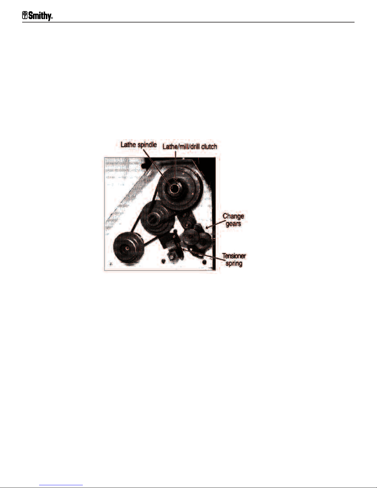
-The gearbox (Figure 5.1 and 5.4) houses the belts that drive the spindle
and change gears for the powerfeed. Select the thread pitch (for threading) or the feed
rate (for turning) by changing the four change gears on the right side of the gear box.
Figure 5.4 The gearbox houses the belts and change gears.
9.
Half-nut Engagement Lever
-This lever, located on the apron, transmit power to
the carriage when rotated 90 degrees to the right.
10.
Half-nut Speed Selector
-The two-speed selector for powering the leadsrew is on
the front of the headstock. The leadscrew turns twice as fast in the II position as in the
Iposition.
11.
Headstock
-The headstock, which is secured to the bed, houses the gears that drive
the powerfeed and the taper bearings that secure the lathe spindle.
12.
Lathe Belt Tensione
r-To adjust the lathe belt (Figure 5.5), pull the tensioner
handle forwardto tighten the belt, back to loosen it.
5-3 For Assistance: Call Toll Free 1-800-476-4849
Midas 1220 XL Operator’s Manual

Figure 5.5 To adjust the tension on the lathe belt, move the tensioner handle forward or back.
13.
Lathe / Mill / Drill Clutch
-The lathe/mill/drill clutch (Figure 5.4) are inside the
gearbox. A three-position clutch, it transfers power to either the lathe or the mill, but not
to both at the same time. To engage it, rotate it slowly while pushing or pulling on the
clutch sleeve. Pulling it to the left runs the lathe, to the right (all the way in) runs the
mill/drill. The middle is neutral.
14.
Lathe Spindle
-The end of the lathe spindle face in the tailstock is the spindle nose.
The spindle nose, which has an MT4 taper, rotates the workpiece and drives lathe chucks
and other work holding devices. All attachments such as three and four jaw chucks bolt
to the spindle flange either directly or via an adapter plate.
15.
Leadscrew
-The leadscrew, which runs the length of the bed, moves the carriage
for lathe turning or thread cutting. It works both manually and under power. You can also
use it manually with the mill.
16.
Locks
-Locks on the cross slide (Figure 5.3) carriage (Figure 5.1), quill (Figure 5.6),
and tailstock (two), Figure 5.1 and 5.7, keep them from moving. During machining, lock
all lock except the one on the part you want to move.
Figure 5.6 The quill moves in and out of the millhead, carrying the spindle.
5-4
Or Visit www.smithy.com
Basic Parts of the MI-1220 XL
17.
Micrometer Dial Collars
-Just inside the handles of the tailstock (Figure5.1),
crossfeed (Figure 5.1), drill press (Figure 5.1), compound feed (Figure 5.1), and
leadscrew (Figure 5.1) there are collars calibrated in inches. The compound feed,
leadscrew, and crossfeed are calibrated in two thousandths, the tailstock in thousandths,
and the drill press in 40-thousandths.
These micrometer dial collars can move independently around the handle shafts. This
independent motion is called float. Floating dials on the cross slide, tailstock, and
leadscrew let you zero the collars at any point and read the feed travel from that point
on the dial for added accuracy.
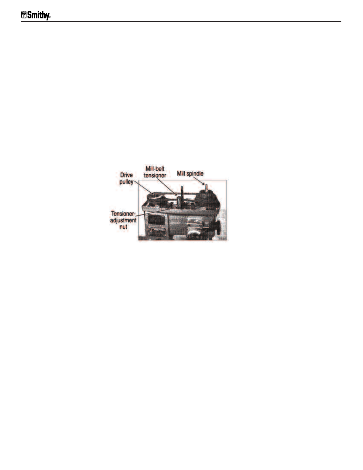
18.
Mill Belt Tensioner -
To adjust the mill belt (Figure 5.7), swing the roller assembly
to the front and place the belt on the back of the roller. Loosen the roller assembly and
slide it back and forth in its slot.
Figure 5.7 With the millhead cover off, you can adjust the mill-belt tension.
19.
Millhead Height Adjustment
-Unlock the mill-head lock and place the height
adjustment handle in one of the three holes in the black collar. Turn the collar to raise
and lower the millhead.
20.
Mill Spindle
-The mill spindle (Figure 5.7) attaches to the quill, which moves in and
out of the head. The quill lock keeps the quill still when you install or remove tools from
it and while milling horizontally. Usually, tools fit into collets that attach through the
spindle via drawbars.
21.
Tailstock
-The tailstock, which provides right-end support for the work, moves
along the bed and can stop at any point. It has an MT3 taper and holds centers, drills,
reamers, taps and other tools. To move the tailstock spindle, turn the tailstock hand
wheel.
To offset the tailstock, adjust the two base-locking bolts (Figure 5.8). To offset to the left,
loosen the left adjusting bolt and tighten the right. To offset to the right, loosen the right
adjusting bolt and tighten the left.
5-5 For Assistance: Call Toll Free 1-800-476-4849
Midas 1220 XL Operator’s Manual
Table of contents
Other Smithy Lathe manuals


Popular Lathe manuals by other brands


Delta
Delta 46-715 instruction manual

Oneway
Oneway 3008 instructions

LNS
LNS QUICK LOAD SERVO S3 Troubleshooting and Spare Parts Manual

Little Machine Shop
Little Machine Shop Mini Lathe user guide

Jet
Jet E-1440VS Operating instructions and parts manual

Central Machinery
Central Machinery 65044 Set up and operating instructions