Smithy Granite 1324 Series User manual

Quick-Start Guide for Smithy Metal-Working Machine
Introduction to the Quick Start Guide
Dec 2008 1
Quick-Start Guide
O
Ov
ve
er
rv
vi
ie
ew
w
Introduction
In This Document
Safety is #1
Questions?
Congratulations on your purchase of a Smithy machine. With proper setup and
care, your machine should provide many years of quality work and enjoyment.
This guide covers general instructions for several Smithy metal-working machines.
You will receive a detailed operating guide, reference manual, and DVD packed in
with your machine. We recommend keeping this quick-start guide with those items
when they arrive.
Enjoy your Smithy machine!
This document covers basic information that you will need to prepare for the
delivery and to begin setting up your Smithy machine. The topics in this document
include:
Smithy machines have been proven to be safe and reliable. However, if abused or
operated improperly, any machine can cause injury to you or others. Please read
this guide and the operating guide carefully before you start machining. Proper use
will create a safe working environment and prolong the life of your machine.
In this manual, the symbols below draw attention to specific operating issues.
For pre-delivery questions not covered in the guide, dial 1-800-476-4849,
Monday through Friday, 8:00 a.m. to 5:00 p.m. (Eastern Standard Time).
Topic
Tracking Your Shipment and Preparing for Delivery
Taking Delivery
Opening the Crate
Removing the Machine from the Pallet
Securing the Machine to a Work Bench
Page
2
4
6
7
11
DANGER If this action is not avoided, it will cause permanent harm to your health,
such as death or serious injury, and it may also cause permanent damage to your machine.
WARNING If this action is not avoided, it can cause potential harm to your health,
resulting in death or serious injury, and has potential to cause serious harm to your machine.
CAUTION If this action is not avoided, it may cause potential harm to your health,
such as minor to moderate injury, and may also cause moderate harm to your machine.
!!
!!
!!

Quick-Start Guide for Smithy Metal-Working Machine
Tracking Your Shipment and Ordering Smithy Accessories
Dec 2008 2
T
Tr
ra
ac
ck
ki
in
ng
g Y
Yo
ou
ur
r S
Sh
hi
ip
pm
me
en
nt
t
The best way to be prepared is to know exactly when your machine will arrive. Your “Pro Number”
in the cover letter serves as your tracking number for your machine. You have several options avail-
able to track your Smithy as it makes its way to you.
Track by Phone
Track Online
Track by Email
Ordering Smithy
Accessories
Estes Express - 1-866-378-3748- Tell the receptionist that answers the phone that
you would like to track your shipment and you will be directed to the next available
customer representative.
UPS - 1-800-PICKUPS - Select #1 and say your tracking number.
U.S. Mail - 1-800-275-8777 - Select desired language and select #5.
Estes- Go to www.estes-express.com. . Enter your pro number in the “Shipment
Tracking Box” and click on submit.
UPS - Go to www.ups.com. Select United States from the drop down field. Click
on the blue arrow. Click on the “Tracking” tab at the top of the screen.
U.S. Mail - Go to www.usps.com. Click on “Track and Confirm”.
UPS - If we are given your email address at the time of ordering, we will enter it
when we fill out your shipping paperwork. UPS will send you automatic updates as
your shipment moves.
We make every effort to ship your complete order by one method. Big. heavy items,
like Smithys, Smithy workstations, and machine stands, are delivered by truck. If
your order contains more than one major item, we make every attempt to get both
on one truck.
We are often able to pack items under 100 lbs inside a larger item’s box and ship
them together. In some cases, orders are too large to be shipped in one box. Items
that are not able to be packaged into larger items’ boxes are shipped through UPS
Ground, and/or U.S. Mail.
Please note, some items - like Smithy 4-Jaw chucks - are packaged in small wood-
en crates, which we DO NOT pack inside with your Smithy in order to avoid dam-
age to your machine. Those items will be shipped via UPS or US Mail.
We handle complex Smithy orders every day - orders usually consisting of at least
one crate and several boxes of varying sizes and weights. We work closely with
Estes and UPS to make sure you’re getting fast, convenient delivery at a reasonable
cost.
Your order may arrive in several installments, over a period of 7-10 days after you
receive this letter.

You will need a work bench that is capable of supporting the weight of your machine
plus up to 300 pounds for the weight of tools, holding devices, work material, etc. If
you purchased one of the optional work benches available from Smithy, these
benches have been designed to support the weight of the specified machine.
You can also make your own work bench. Just make sure it is sturdy enough to
support the machine (plus 300 pounds) and that the bench top is rigid, level, and
well-supported. The height should be such that machine controls are at waist level.
Your work bench should be located in a vibration-free area with a floor that is
designed to support the full weight of the bench, machine, accessories, and materi-
als.
Smithy strongly discourages the use of casters or wheels on metal-working
machine benches. The weight of the machine could result in the bench tip-
ping while being moved. Once the machine is mounted, consider your work
bench to be permanent. If you must move the machine, first remove it from
the bench.
Set up the work bench so you have plenty of working space. Leave at least 3 to 4
feet of clearance on the operating side of the machine (at left in the drawing below).
Note the suggested clearances for the other sides of the machine.
Machines with 110-volt motors require a properly grounded (3-wire), 110-volt AC
electrical circuit protected by a 20-ampere (20 amp) breaker. Machines equipped
with 220-volt motors require a 220-volt AC circuit single phase protected by a 15-
ampere (15 amp) 220-volt breaker. Preferably, the outlet should be on a separate
circuit. Smithy also recommends that you not use an extension cord. However, if
you do, ensure that the cord is rated for a current of at least 20-amperes. Please
check with your local electrical codes when installing a new circuit into your work
area.
Quick-Start Guide for Smithy Metal-Working Machine
Preparing for Delivery
Dec 2008 3
P
Pr
re
ep
pa
ar
ri
in
ng
gf
fo
or
rD
De
el
li
iv
ve
er
ry
y
Here are some things you can do to prepare your shop or work space for your new Smithy
machine.
Work Bench
DANGER!
Clearance
Power
Requirements
!!
Millhead
Leave 2 to 3 feet to allow for millhead to swing
and for access to the back of the machine.
Tailstock
Operating Side (Front)
Gear/Pulley Enclosure
Leave 2 to 3 feet to allow stock
to hang over the end of the bed.
Leave 2 to 3 feet to open
enclosure or pass working
stock through the spindle.
Leave 3 to 4 feet to allow working space.
Lifting Handle (not visible on drawing)
Lifting
Handle
Lifting
Handle
Lifting Handle

Quick-Start Guide for Smithy Metal-Working Machine
Taking the Delivery
Dec 2008 4
T
Ta
ak
ki
in
ng
gD
De
el
li
iv
ve
er
ry
y
Here are some recommendations for taking delivery of your Smithy machine.
Receiving the
Machine
Weight of the
Machine
Vehicles
Inspecting the
Crates or Cartons
In most cases, you will pick up the crated machine at a trucking terminal or depot.
Before picking up your machine, contact the delivery terminal, ask about the loading
arrangements, and arrange for timely pick-up. You may also be able to arrange to
have the machine delivered to your shop location if you have not already done so.
The table below lists the approximate shipping weight and crate dimensions for
Smithy metal-working machine models and optional benches. Use these weights
and dimensions in planning to pick up your order.
Smithy recommends that you use an open-bed pick-up truck, a cargo van, a cube
van, or a sturdy trailer to pick up your machine. Smaller vehicles may not have the
load capacity or sufficient clearance for loading at the shipping terminal.
On arrival, thoroughly check each crate and carton for signs of loss or damage.
While a shipping company employee is present, open any crate or carton that
shows signs of loss or damage.
Examine the contents with the shipping company employee.
If any damage is present, record an exact, detailed description of the results of the
examination on both the shipper’s and your delivery receipt. Be specific.
Model Shipping Weight
(pounds)
Crate Dimensions
(inches)
Midas 1220 XL 530 44 x 23 x 38
Midas 1220 LTD 620 44 x 23 x 38
Midas 1231 LTD 670 44-4/3 x 22-3/4 x 38
Granite 1324 Series 775 49-1/2 x 22-3/4 x 43-1/4
Granite 1340 Series 815 65 x 22-3/4 x 43-1/4
CX-329 840 39 x 43 x 45
CX-239 1075 70 x 30 x 30
LX-329 1058 32 x 40 x 54
LX-1340 1500 36-1/2 x 30 x 30
Work Bench (80-000) 1 carton @ 140 60 x 25 x 13-1/4
Work Bench for CZ-239 (80-010) 1 carton @ 48
1 carton @ 68
1 @ 26 x 15 x 11
1 @ 26 x 14 x 18
Work Bench for CX, LX 1 carton @ 76 1 @ 20 x 25 x 17
Work Bench for LZ-1340 1 carton @ 90
1 carton @ 90
1 @ 27 x 17 16
1 @ 27 x 16 x 12
Work Bench for GN-1340 Series
(80-020)
1 carton @ 66
1 carton @ 49
1 @ 30 x 16 x 18
1 @ 30 x 14 x 18
Work Bench (80-045) 1 carton @ 160 1 @ 59-1/2 x 25 x 13-1/2
Continued on the next page...
Quick-Start Guide for Smithy Metal-Working Machine
Taking the Delivery
Dec 2008 5
T
Ta
ak
ki
in
ng
gD
De
el
li
iv
ve
er
ry
y,
,continued
Important Note
Loading the
Machine
The crate is intended to protect the machine; damage to the crate does not
necessarily mean that your Smithy machine has been damaged. However,
noting any damage to the crate on the delivery receipt will make it much easi-
er to substantiate a claim if there actually is damage.
After you have inspected the crate and signed for the machine, a shipping company
employee will load your machine into your vehicle. The loading procedure depends
upon your vehicle and the facilities at the terminal.
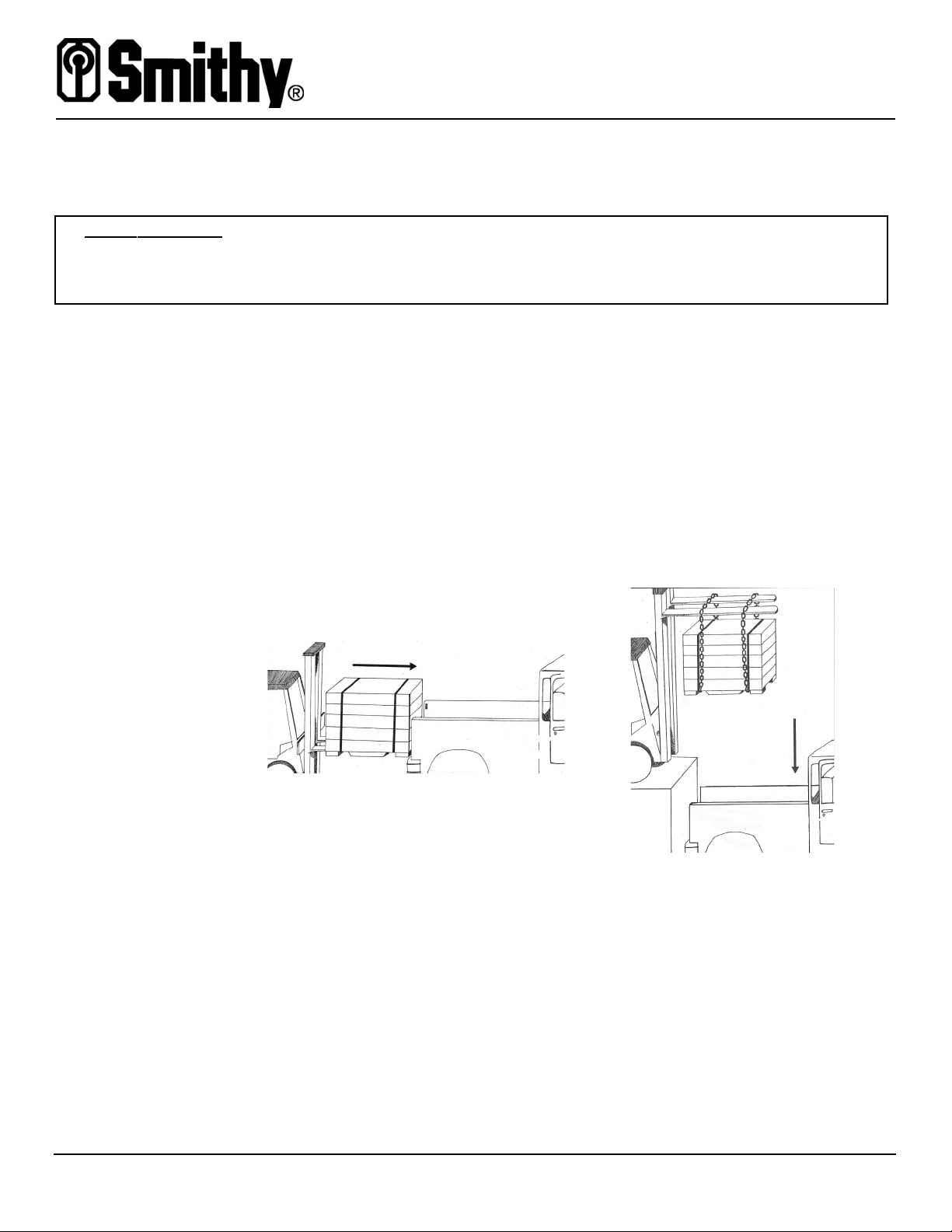
If the shipping company’s forklift is not restricted to the loading dock, you can have
the crate loaded directly into the truck or trailer bed with the forklift as shown below
at left.
If the forklift is restricted to the loading dock, chains or straps can be used to lift the
crate and lower it into the truck or trailer bed as shown below at right. Of course,
this arrangement will not work well for smaller, closed vehicles.
Regardless of how you load the machine, always be sure to tie the load down
securely so that it does not shift during transport.
Use this procedure if the
forklift is restricted to the
loading dock.
Use this procedure if the forklift is
not restricted to the loading dock.
Quick-Start Guide for Smithy Metal-Working Machine
Opening the Crate
Dec 2008 6
O
Op
pe
en
ni
in
ng
gt
th
he
eC
Cr
ra
at
te
e
Follow these steps to open the crate.
CAUTION!
Step 1
Step 2
Step 3
Step 4
CAUTION!
Step 5
Step 6
Step 7
Wear leather work gloves and safety glasses for this operation, especially
when cutting the metal bands, which are under tension.
Remove the packing list from the plastic bag attached to the crate and put the docu-
ment in a safe place.
Cut the metal bands encircling the crate with tin snips. Note: If you have ordered a
Granite or Granite Industrial machine, the plywood crate cover has been
screwed to the pallet. Unscrew the top two screws on the two plates on both
sides of the crate and the one plate on the end of the crate.
Determine the end of the crate at which the tailstock is located. You may need to lift
the crate 3 or 4 inches, and run your hand along the base. If you feel 10 to 12 inch-
es of sheet metal, you need to the lift the opposite end.
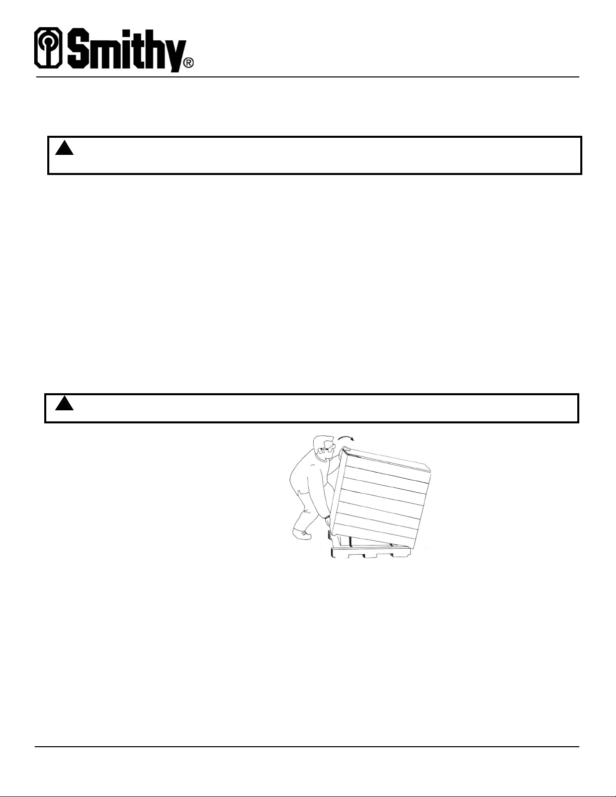
Using the proper lifting techniques, lift the tailstock end of the top of the crate
upward. To avoid pinching your fingers while lifting, place your hands toward the
corners of the crate and not in the middle. While lifting, pull the crate toward you
slightly so that it easily clears the tailstock.
Crate covers can weight up to 100 pounds. Ask a friend or family member to
help, if necessary.
Set the crate aside, out of the immediate work area. You may want to keep the
crate in case you ever need to return the machine for repair.
Check the packing list against the contents of the crate to ensure that everything
listed is accounted for in your shipment. Also, check the contents of the crate
against the inventory lists in the operating guide to ensure that all machine compo-
nents are present.
Check the machine carefully for signs of damage, especially if you noted damage to
the crate earlier.
!!
!!
Quick-Start Guide for Smithy Metal-Working Machine
Moving Your Smithy from the Pallet
July 2006 7
M
Mo
ov
vi
in
ng
gY
Yo
ou
ur
rS
Sm
mi
it
th
hy
yf
fr
ro
om
mt
th
he
eP
Pa
al
ll
le
et
t
Before removing your machine from the pallet, review the instructions on page 11 for securing
your machine to the work bench. Depending on the model, your fully assembled Smithy machine can
weigh 900 pounds or more. Use a mechanical device to lift the entire machine, or disassemble some
parts of the machine and reassemble them on the bench, as outlined in this guide.
Important Note
Removing with
Mechanical
Power
Step 1
Step 2
Step 3
Step 4
Step 5
Step 6
Step 7
DANGER!
CAUTION!
For your safety, Smithy recommends that at least one additional person be
present when moving your machine, even if you are using a mechanical lifting
device.
Follow these steps to remove the machine from the pallet if you have a hoist or
mechanical lift to position the machine on the stand. You can obtain a suitable
engine hoist from an equipment rental center.
Remove any hold-down straps and the plastic protective covering.
Remove the Smithy boxes that contain your Quick Start Pack.
Use wrenches to remove the nuts and bolts that hold the machine base to the pal-
let.
Pull out the four lifting handles in the base of the machine. There are two lifting han-
dles on the operator’s side of the machine and two on the back side of the machine.
On each side, there is a lifting handle near the millhead and one near the tailstock.
Remove levers or wheels that could be damaged by lifting chains or straps.
Move the table and tailstock as far to the right as possible (toward the end of the
machine) to balance the weight of the machine.
Attach chains or lifting straps to the lifting handles. If necessary, you can unscrew
the ends of the lifting handles to slide the loop of a lifting strap onto the handle. Be
sure all points of attachment are snug and cannot shift.
If you removed the lifting handle ends, be sure to replace them before lifting
to prevent the straps from sliding off the handles.
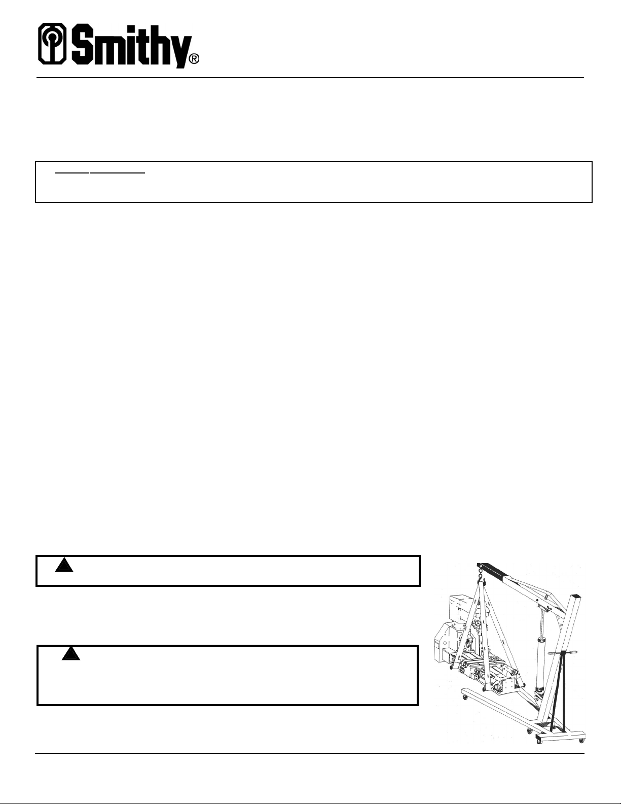
Ensure that the machine is not plugged into elec-
trical power.
The drawing shows a properly rigged lifting arrange-
ment.
Viewed from the operator’s side of the machine,
the lifting straps must be attached from the right
front to the right back and left front to the left
back. Do not cross left and right straps.
!!
!!
Continued on the next page...

Quick-Start Guide for Smithy Metal-Working Machine
Moving Your Smithy from the Pallet
July 2006 8
MMoovviinnggYYoouurrSSmmiitthhyywwiitthhMMeecchhaanniiccaallPPoowweerr,,continued
Step 8
Step 9
Step 10
Removing
without
Mechanical
Power
Step 1
Step 2
Step 3
Step 4
CAUTION!
Lift the machine off the pallet with a lifting device, such as a hoist, keeping it as low
to the ground as possible. Move the machine to the location of the permanent work
bench.
Lift the machine just high enough to clear the top of the work bench.
Move the machine over the work bench and gently set it down in position.
Follow these steps to remove the machine from the pallet if you do not have access
to a hoist or mechanical lift. The objective is to remove as much of the weight as
possible before lifiting. Plan on having four people available to lift the machine onto
the bench.
Remove any hold-down straps and the plastic protective covering.
Use wrenches to remove the nuts and bolts that hold the machine base to the pal-
let.
Remove the Smithy boxes that contain your Quick Start Pak.
Remove the Millhead (see diagram below)
Lock the millhead locking handle. Using a sharp knife or razor blade, score the paint
where the millhead attaches to the headstock. Depending on the model, you may
need to open the gear enclosure and remove up to two screws.
To access and remove the four hex-socket capscrews at the base of the millhead
support column, raise the millhead and offset at 45º.
Verify that the millhead is locked to the column. Then lift the millhead and column
off the lathe head. You may have to rock it back and forth gently while lifting it.
The millhead can weigh up to 100 pounds. Ask a friend to stabilize the mill-
head to prevent it from tipping while you remove the last capscrew. Tippage
could result in injury to your or damage to your machine.
!!
Continued on the next page...
Headstock
Millhead
Millhead Locking Handle
Capscrew Locations (4)
Column Base

Quick-Start Guide for Smithy Metal-Working Machine
Moving Your Smithy from the Pallet
Dec 2008 9
MMoovviinnggYYoouurrSSmmiitthhyywwiitthhoouuttMMeecchhaanniiccaallPPoowweerr,,continued
Step 5
Important Note
Step 6
Remove the Tailstock (see diagram below)
Loosen the locking handle and slide the tailstock off the end of the bed.
Hold the tailstock gib in place so it does not fall out. There is a locking pin
behind the lock handle that can also fall out. Watch carefully as you remove
the tailstock.
The gib for the 1200 series is on the operator’s side of the machine.
Remove the Lathe Chuck (see diagram below)
Removal of the lathe chuck depends on which Smithy machine you have.
GN-1300 Series
Using the chuck key supplied with the
machine, turn the square sockets in the
spindle flange counterclockwise until the
hashmarks are aligned. Remove the chuck
without letting it fall onto the machined
ways.
All Other Machines
Using a wrench, loosen the bolts on the
back side of the lathe spindle flange.
After all the bolts have been removed,
use a rubber mallet or the palm of your
hand to loosen the chuck from the spin-
dle flange.
Chuck
Mounting
Bolts
Locking
Handle
Gib
Chuck
Mounting
Sockets
Continued on the next page...

Quick-Start Guide for Smithy Metal-Working Machine
Moving Your Smithy from the Pallet
Dec 2008 10
MMoovviinnggYYoouurrSSmmiitthhyywwiitthhoouuttMMeecchhaanniiccaallPPoowweerr,,continued
Step 7
Important Note
Important Note
Step 8
Step 9
Step 10
Step 11
Remove the Carriage Assembly
Smithy does not recommend that you remove the carriage assembly unless it
is absolutely necessary. It is very easy for several small parts to fall into the
apron assembly and cause problems later.
If the carriage assembly must be removed, start with the coupler sleeve that con-
nects the leadscrew to the driveshaft on the left-hand side of the leadscrew (see
blow-up at left in drawing below). It is pinned to the leadscrew by a tapered pin.
Locate the smaller end of the pin and drive the pin out.
On the right trestle, remove the hex-socket capscrews (see blow-up at right in draw-
ing below). Note: Depending on the model, the cap screw for removing the testle
could be located on either the operator’s side (as shown below) or at the end of the
bed. Tap lightly on the right trestle to loosen it from the lathe bed. Do not remove
the locating pins. You will need them in place to realign the carriage. Engage the
half-nut, run the carriage to the right and off the rack, and slide the carriage off the
bed. **
As you are removing the carriage, the gib and locking pin could fall out. Be careful
not to lose them.
The drawing above is shown with the tailstock in place. However, the tailstock
will need to be removed before the carriage can be removed. See Step 6
above.
With a person at each lifting handle, use proper lifting techniques to move the
machine to the location of the permanent work bench. Proper lifting technique
includes squatting down so that you use your leg muscles to lift rather than bending
over at the waist and risking a back injury.
Lift the machine high enough to clear the top of the work bench.
Move the machine over the work bench and gently set it down in position.
After following the instructions on page 11 to secure the machine to the bench,
reassemble any parts that were removed.
** On models: GN-1324, GN-1340, GN-1324-I, GN-1340-I, MI-1220 LTD & MI-1231 LTD

Quick-Start Guide for Smithy Metal-Working Machine
Securing the Machine to the Work Bench
Dec 2008 11
S
Se
ec
cu
ur
ri
in
ng
gt
th
he
eM
Ma
ac
ch
hi
in
ne
et
to
ot
th
he
eW
Wo
or
rk
kB
Be
en
nc
ch
h
If you have not already done so, you will need to assemble or build the work bench you intend to
use. Once the machine is resting on the permanent work bench, you will need to secure it to the
bench top with bolts.
Mounting
Hardware
Important Note
Aligning the
Machine
Important Note:
There are four mounting-bolt holes on the machine base. Follow the mounting hard-
ware recommendations shown for the benches available for purchase from Smithy.
Use equivalent hardware if you have built your own work bench, adjusting the
length of the bolts for the thickness of your bench top.
MI-1220Xl &, MI-1220 LTD
Metal Chip Tray Bench (80-030 or 80-045)
3/8” x 3-1/4” bolts, 3/8” washers, and 3/8” nuts
Maple Top Bench (80-000)
3/8” x 3-1/4” lag bolts
GN-1324/GN-1324 MX and GN-1324 IMX
Metal Chip Tray (80-030 or 80-045)
3/8” x 2” bolts, 3/8” washers, and 3/8” nuts
Maple Top Bench (80-000)
3/8” x 2” lag bolts
The bench for the Granite 1340, 1340 MX, 1340 IMX and for all Dedicated
Lathes and Mills include all necessary mounting hardware.
The chip tray of the 80-045 bench comes with three mounting pads for the
machine, two mounting pads are pre-drilled. The two pads that are closest together
support the headstock end of the machine and should be on the left side when fac-
ing your work bench from the operating side.
The easiest way to align the machine base to the bolt holes is to suspend the
machine just above the bench top with a hoist. Put mounting bolts in opposite cor-
ners of the machine base to use as guides as you gently lower the machine onto
the bench top. You can then add bolts to the remaining mounting holes and tighten
all mounting hardware. If you are using a bench with a chip tray, be sure to align the
mounting holes on the base to the holes in the chip tray.
If you are using the maple top (80-000) or a top for which holes must be drilled,
gently lower the machine onto the bench top, mark the location of the mounting
holes, lift and move the machine, drill pilot holes for the lag bolts, move the machine
back into place, and then fit and tighten the bolts. You can also lay out the bolt pat-
tern as shown in the diagrams on the pages that follow.
All four holes are not accessible on all machines.
Continued on the next page...
Quick-Start Guide for Smithy Metal-Working Machine
Securing the Machine to the Work Bench
Dec 2008 12
SSeeccuurriinnggtthheeMMaacchhiinneettootthheeWWoorrkkBBeenncchh,,continued
Bolt Patterns
1200 Series
Mounting Bolt
Layout
1300 Series
Mounting Bolt
Layout
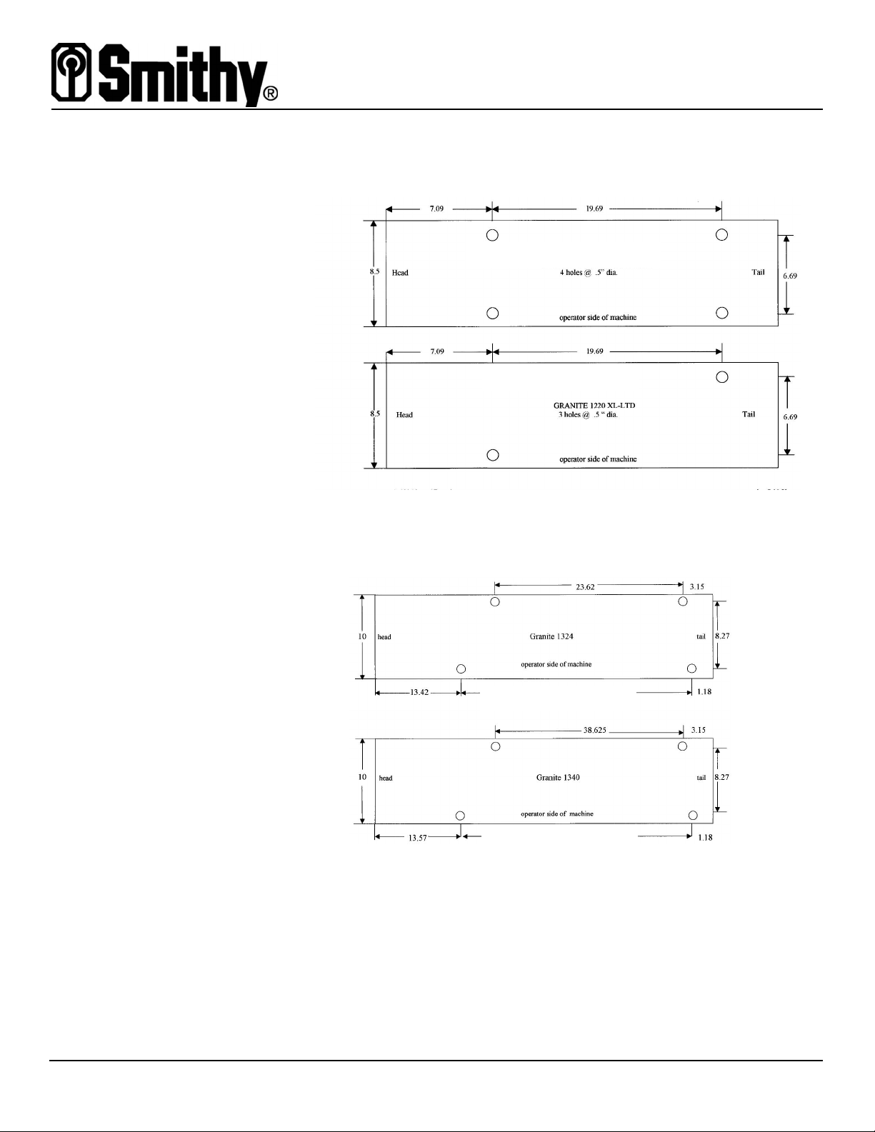
If you have made your own work bench, use the lay-out diagrams below to pre-drill
holes for the mounting hardware.
Continued on the next page...
Midas 1220 LTD
3holes @ 0.5 inch diameter
Midas 1220 XL
3holes @ 0.5 inch diameter
GN-1324, GN-1324 MX & IMX
4 holes @ 0.5 inch diameter
GN-1340, GN-1340MX & IMX
4 holes @ 0.5 inch diameter

Quick-Start Guide for Smithy Metal-Working Machine
Securing the Machine to the Work Bench
Dec 2008 13
SSeeccuurriinnggtthheeMMaacchhiinneettootthheeWWoorrkkBBeenncchh,,continued
CX-329 & LX-329
Mounting Bolt
Layout
CZ-239 Mounting
Bolt Layout
LZ-1340
Mounting Bolt
Layout
Ready for
Cleaning and
Setup!
Note: Hole size is 1/2”. Use 3/8”
to mount to your stand.
When you have completed securing the machine to the bench top, you are ready to
begin cleaning and setting up the machine. Watch the DVD and read your operation
guide thoroughly to familiarize yourself with your machine and the operations of
your machine.
Pulleybox
69.25”
10”
8.25”
12.25”
8.25”
0.75”
11.5” 3.75”4.5”
0.75”
7”
0.75” 0.75”
6.875”
0.625”
1.5”
LZ-1340 Bolt Pattern
- All holes are measured to center
- Hole diameter is 1/2”
- Use 7/16” bolts
- Drawing is not drawn to scale
This manual suits for next models
11
Table of contents
Other Smithy Lathe manuals


