Smokeeter SE 10 User manual

Electronic Air Cleaner
MODEL SE 10
OWNER’S MANUAL
To Place an Order Call ACS, Inc. @(800) 878-5030
1
POWER REQUIREMENTS
115 VAC, 60 Hz,
.9 Amps Max.
POWER CORD
10' 16 ga. with molded
grounded plug
POWER CONSUMPTION
104 Watts (Max.)
AIR HANDLING CAPACITY
90 to 250 CFM
WEIGHT
HANGING................27 lbs (10 KG)
SHIPPING................32 lbs (12 KG)
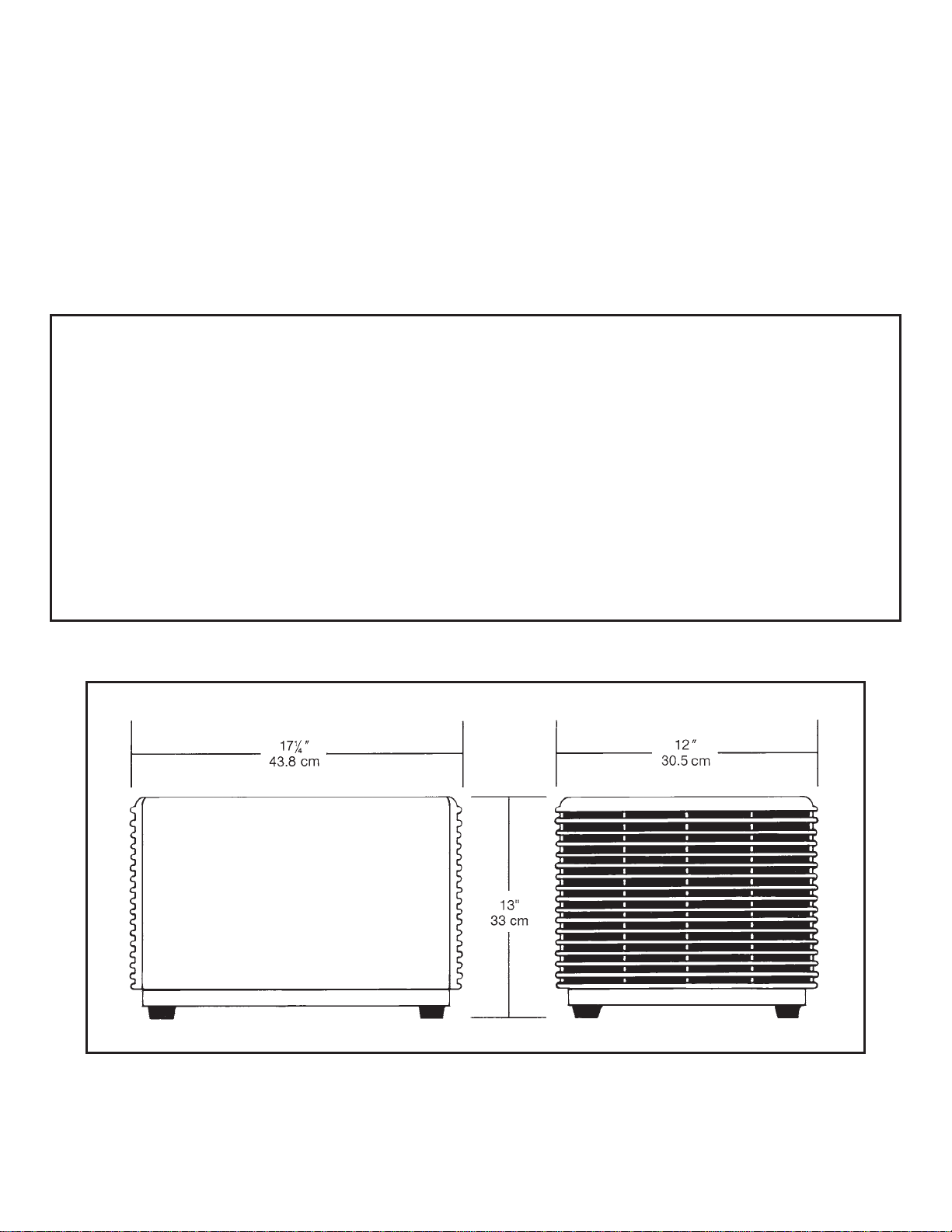
DIMENSIONS
Height Width Length
13" 12" 171⁄4"
(33 cm) (30.5 cm) (43.8 cm)
SPECIFICATIONS
MODEL SE 10

2
MODEL SE 10
TABLE OF CONTENTS
SECTION PAGE
I. Introduction 3
II. Inspection of Equipment 3
Ill. How Your SMOKEETER/CRYSTAL-AIRE Operates 3
IV. Installation 4
V. Operation 4
VI. Cleaning 5
THE FOLLOWING INFORMATION IS PROVIDED
FOR TRAINED SERVICE PERSONNEL ONLY
VII. Periodic Maintenance and Troubleshooting 6
VIll. Replacement Parts 8
IX. Illustrated Parts 10
Unicell Assembly 12
Wiring Diagrams 13
IMPORTANT NOTICE
BEFORE OPERATION, PLEASE REMOVE ALL PACKING MATERIAL FROM
INSIDE UNIT. THIS CAN INCLUDE MARKED TIE DOWN SCREWS,
CARDBOARD, STYROFOAM AND PLASTIC WRAP ON CARBON FILTER.
MODELS VARY IN MATERIAL USED.
3
I. INTRODUCTION
Your new air cleaner is the most advanced product of
its type on the market today and will provide a safer,
healthier environment. As you begin its operation, we
would like to remind you of a few important facts.
First, we appreciate your business, and because we
appreciate your business, we have manufactured an air
cleaner engineered to rigid specifications, incor-
porating the latest technological advances. It is built
using the best materials available and is subjected to
rigorous quality control checks. A warranty backs
every air cleaner that leaves our factory.
Second, like any piece of equipment, your air cleaner
needs periodic maintenance. Properly cared for, it will
operate at peak efficiency for many years to come.
Finally, while we hope you never have any problems,
United Air Specialists, Inc. (UAS) is always ready to
lend assistance through our factory-trained sales-
people. Should you need information or service, con-
tact your local salesperson or the Customer Service
Department at United Air Specialists, Inc., 4440 Creek
Road, Cincinnati, Ohio 45242, 1-800-252-4647.
II. INSPECTION OF EQUIPMENT
Upon receipt of your SMOKEETER/CRYSTAL-
AIRE, check for any shipping damage. A damaged
carton indicates that the equipment may have
received rough handling during shipping that may
have caused internal damage. Notify your delivery
carrier and enter a claim if any damage is found.
Before operating unit, remove all packing material
including carbon afterfilter, packaging and unicell
shipping screws.
III. HOW YOUR SMOKEETER/
CRYSTAL-AIRE OPERATES
The air mover draws air through the ionizer. As par-
ticles pass through the ionizer section, they are given
an intense positive charge. These charged particles
are then collected on cell plates. The clean air is
redistributed into the room through an outlet diffuser.
An activated carbon afterfilter helps control odors
in the air.
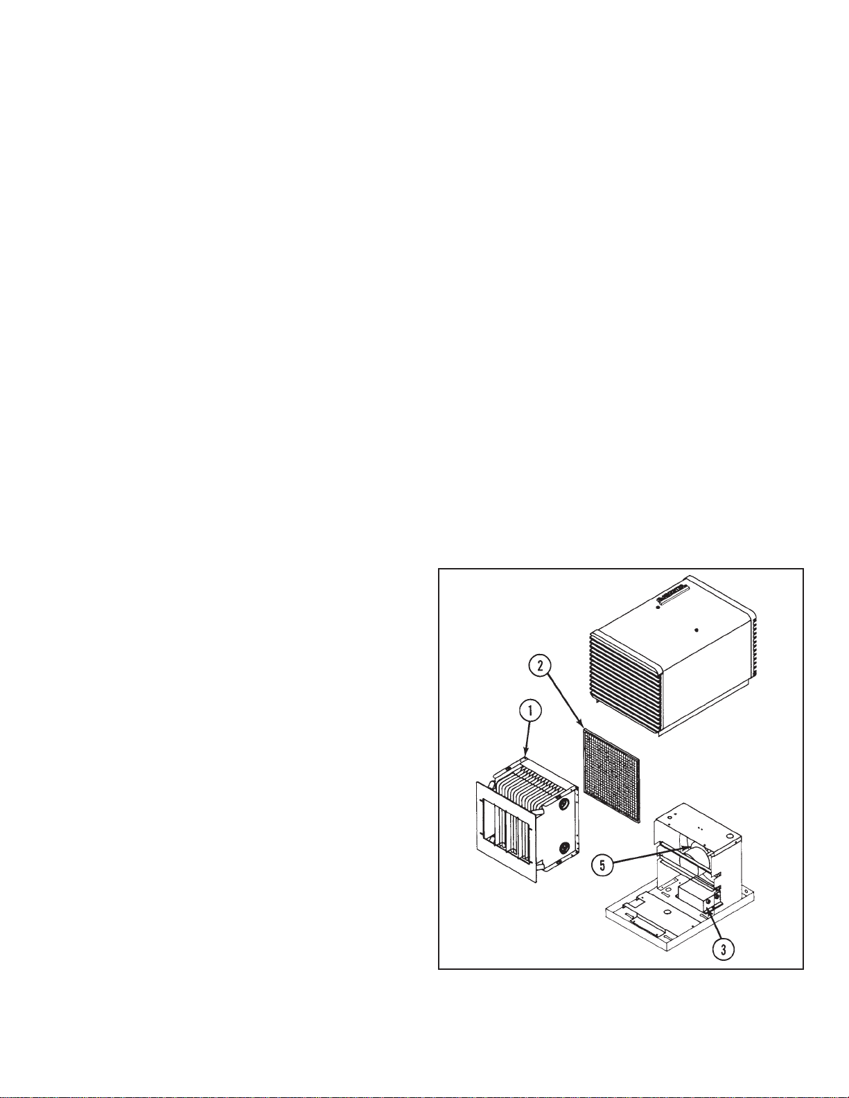
COMPONENTS MAKE IT WORK
(See Figure 1)
1. UNICELL is comprised of the ionizing section and
the collecting section. The ionizing section is made
of fine tungsten wires supported between metal
plates. When high voltage is applied to these
parts, a “corona” field is generated, imparting a
high voltage charge on particles that pass through
it.
The collection section is made up of a series of flat
metal plates. These plates act like a magnet and at-
tract the charged particles, removing them from the
air. The plates are alternately charged positive and
ground. The positive plates repel the particles while
the ground plates attract them, yielding a very high
efficiency.
2. ACTIVATED CARBON AFTERFILTER helps remove
odors in the air.
3. POWER PACK is a dual high voltage supply. It sup-
plies 12,000 volts DC to the ionizer and 6,000 volts
DC to the collection cell.
4. SOLID-STATE SPEED CONTROL (not shown) allows
airflow adjustment.
5. AIR MOVER is a three blade fan designed for quiet
operation. The motor features an automatic reset
thermal protector.
FIGURE 1
4
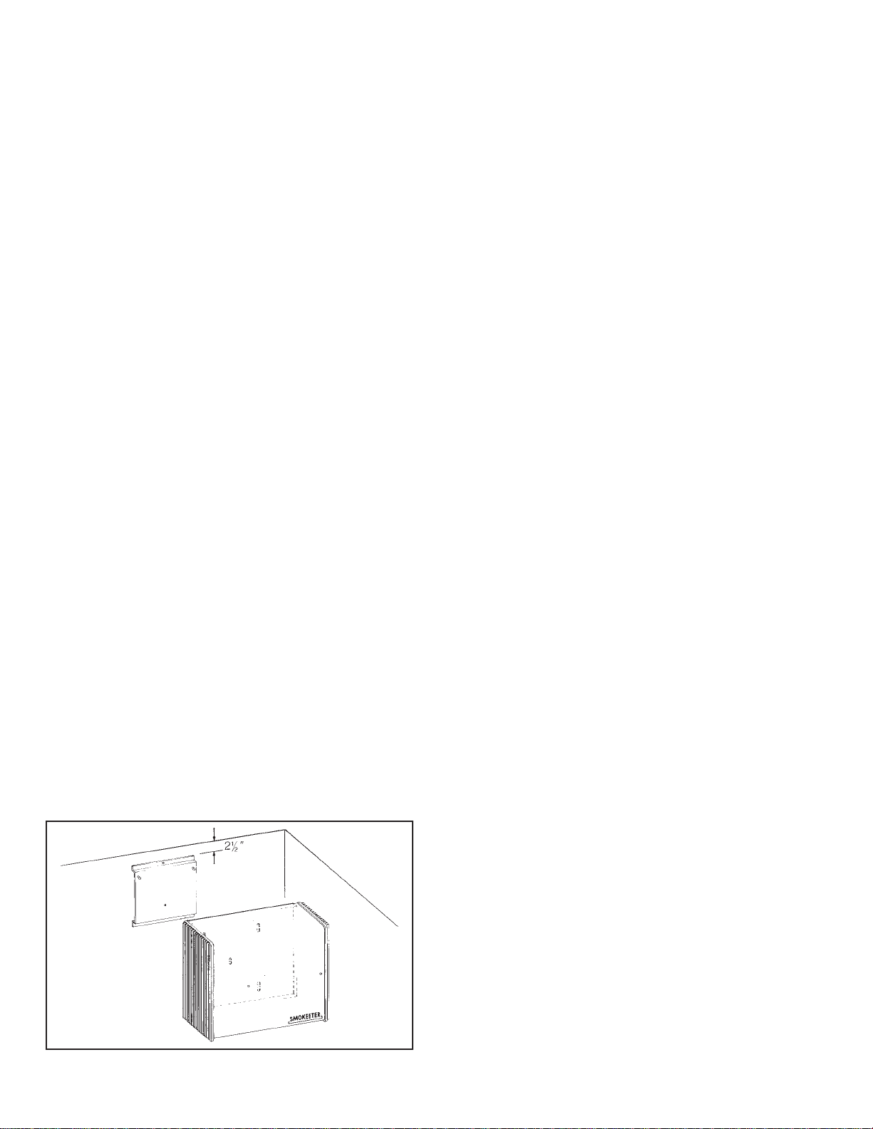
FIGURE 2
IV. INSTALLATION
NOTE: This product has been designed specifically
for commercial and residential applications
such as offices, conference rooms, cafeteria
and living areas. United Air Specialists
assumes no responsibility for those applica-
tions unlike the aforementioned.
The SMOKEETER/CRYSTAL-AIRE is designed to
draw the contaminated air through the unit and
exhaust clean air back into the room. The clean
air is used to push contaminated air around the
room to the inlet of the unit. Directions of air
patterns and proper placement of the unit should
be established by your local SMOKEETER/
CRYSTAL-AIRE distributor or by United Air
Specialists, Inc.
The SMOKEETER/CRYSTAL-AIRE can be installed
by:
1. Placing on desk, file cabinet or other stable surface.
2. Mounting on a wall.
CAUTION: Power connection — The power cord
on this product should be used in con-
nection with a properly-sized and
appropriately located 115 VAC ground-
ed outlet receptacle. No alteration of
the power cord should be attempted
nor should extension cords be used.
To reduce the risk of electric shock,
this equipment has a grounding-type
plug that has a third (grounding) pin.
This plug will only fit into a grounding-
type power outlet. If the plug does not
fit into the outlet, contact qualified
personnel to install the proper outlet.
Do not alter the plug in any way.
WALL MOUNTING OPTION
Awall mounting bracket is provided for mounting
the unit on walls.
Securely attach the wall mounting bracket against
the wall, allowing 21⁄2" from the ceiling for clearance
of the unit (see Figure 2).
WARNING: Use fasteners and anchoring devices that
will ensure support of the 27 pound unit.
After the mounting bracket is attached, remove the
unicell assembly from the cabinet to facilitate
handling and lighten the weight (see Removing
Components — page 5).
Slide the keyhole slots in the unit base over the
studs on the wall bracket and allow the base to drop
into place, resting on the studs. Using the screw
provided with the unit, secure the base to the moun-
ting bracket.
The SMOKEETER/CRYSTAL-AIRE should now be
tested for secure support.
Reinstall the components and attach the cabinet.
Plug the unit into a grounded 115 volt AC outlet.
REVERSING AIRFLOW
The unit is shipped to you ready for installation
in a left-to-right airflow configuration. If a right-
to-left airflow is desirable, simply turn unit 180°
(unit will be upside down). Remove plastic logo and
place upright in same position (logo is now located in
upper left).
V. OPERATION
For best results and to assure maximum air quality,
your SMOKEETER/CRYSTAL-AIRE should be
started before the air becomes contaminated. An
indicator lamp on the unit is illuminated during
normal operation of both the power pack and the
unicell and will dim when the unicell requires
servicing. A solid-state speed control switch allows
you to adjust the fan speed. If you notice a decrease
in cleaning efficiency, increase the fan speed to
increase the unit’s effectiveness.
FOR YOUR INFORMATION — Each SMOKEETER/
CRYSTAL-AIRE has been thoroughly tested prior to
shipment from the factory. Even so, there may
be some initial arcing of the components at start
up. The noise should cease after a few minutes
of operation.
5
VI. CLEANING
CAUTION: Servicing this product for purposes other
than routine cleaning of the collection com-
ponents (unicell) should be performed by
trained authorized service personnel. Any
effort to exceed this service by non-quali-
fied personnel may lead to bodily injury
and/or equipment failure.
This section is defined for cleaning and periodic main-
tenance. The internal components must be removed
prior to cleaning.
CAUTION: The unit should be inspected frequently
and dirt removed to prevent excessive
accumulation which may result in flashover
or fire damage. An electrical interlock is
provided for protection — do not defeat its
purpose.
HOW TO REMOVE COMPONENTS
1. Turn off the SMOKEETER/CRYSTAL-AIRE.
•Loosen the two knobs and lift cabinet wrapper.
Wait approximately 15 seconds to allow for any
residual high voltage to bleed off.
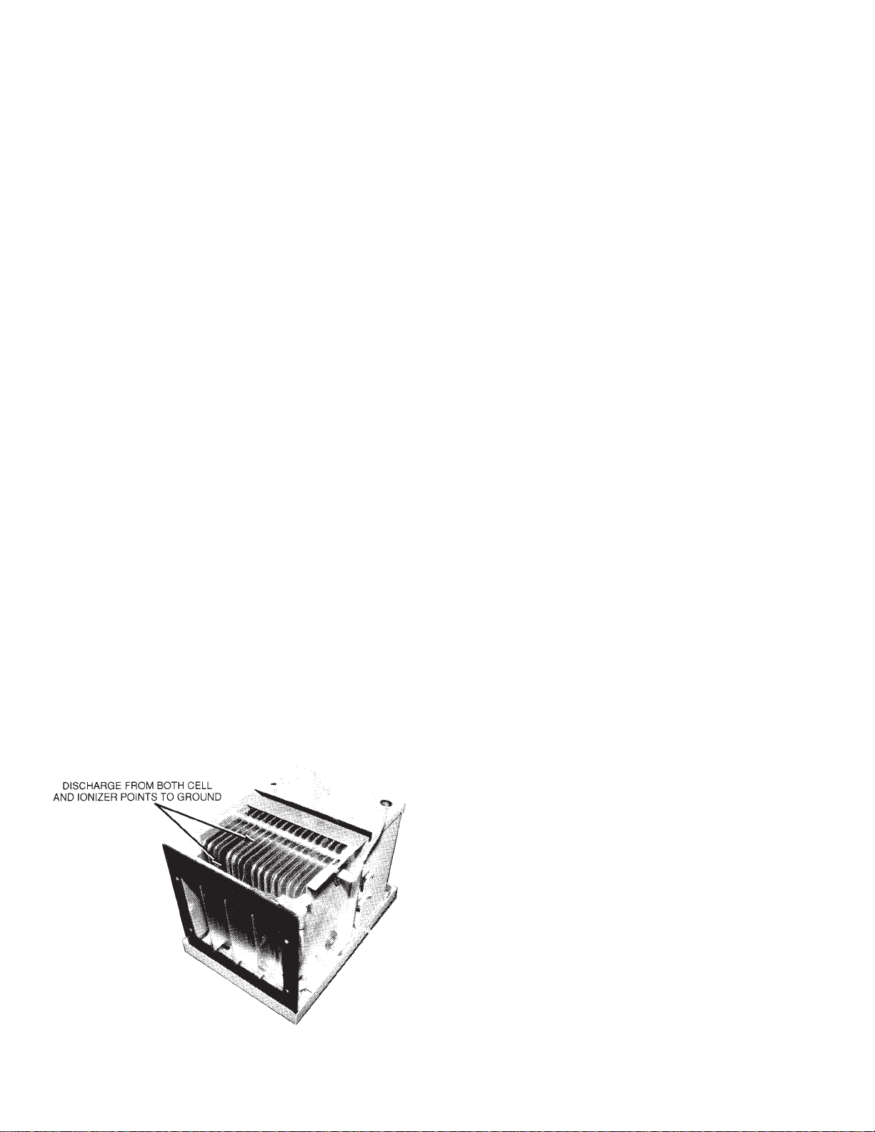
•For added safety, manually discharge the unicell
in the following manner. Place the blade of a
common screwdriver (with insulated handle)
across the ionizer wire and ionizer fin. Next,
place the screwdriver blade between any two
cell plates. This will remove any residual charge
that may not have bled off. Disconnect high volt-
age wires (see Figure 3).
2. Remove the carbon afterfilter by sliding from the
track.
3. Slide the unicell from the cabinet.
CLEANING
Major cleaning is confined to the unicell and the inside
cabinet. The unicell and cabinet should be cleaned
periodically to assure continued efficiency. Cleaning
may be required from once a month to once every four
months depending on the air quality.
NOTE: The carbon filter cannot be cleaned and
needs to be replaced once every six to 12
months.
1. The unicell can be cleaned by soaking in a hot solution
of SMOKEETER/CRYSTAL-AIRE brand detergent for
30-60 minutes. If possible, agitate the solution to aid
in dirt removal. If agitation is not possible, soaking time
should be increased.
CAUTION: Do not use temperature exceeding 160°F
and do not steam clean as this may cause
permanent damage to the unicell. If deter-
gent other than SMOKEETER/CRYSTAL-
AIRE is used, care must be taken to assure
that it contains an aluminum inhibitor so
that it does not attack the aluminum com-
ponents. Be sure to follow manufacturer’s
cleaning instructions.
2. Remove the components from the detergent bath
and immediately flush away any residue and rinse
thoroughly with hot water. Shake off excess water
and let components dry for 30-60 minutes. Set the
cell so that its plates are in a vertical position for
drainage.
3. Vacuum clean the interior of the cabinet and clean
off all electrical connections before reinstalling the
components.
4. Clean the outside cabinet and inlet/outlet grilles by
wiping down with a lint free soft cloth and a suitable
household cleaner, (i.e. Mr. Clean, 409, etc.)
5. Reinstall the components.
6. Attach high voltage wires.
7. Reinstall cabinet wrapper.
8. Plug in and turn on unit.
FIGURE 3
6
VII. PERIODIC MAINTENANCE AND
TROUBLESHOOTING
The following sections are for the use of trained service
personnel only.
WARNING — THE FOLLOWING PROCEDURES WILL
EXPOSE HAZARDOUS LIVE AND MOVING PARTS. DIS-
CONNECT AIR CLEANER BEFORE PROCEEDING.
All SMOKEETER/CRYSTAL-AIRE air cleaners are
manufactured to give years of trouble-free
performance. As with any piece of equipment,
however, breakdowns can occur. Due to the
simplicity of design, breakdowns are restricted to
these components:
— the air mover*
— the power pack
— unicell
— speed control switch
— safety switch
— indicator lamp
This section covers the troubleshooting procedure and
a guide which will enable you to determine the cause of
most problems. Refer to Section VIII for replacement
parts.
*This model is equipped with a permanently lubricated
motor and no further oiling is required.
COMPONENT FUNCTION
1. Power Pack — the electrical circuit is designed
around the power pack which contains the necessary
components to convert 115 Volts, single-phase, 60
hertz to the high voltage DC required for the unicell.
2. Unicell Ionizing Section — the ionizing section
supports four tungsten wires charged positive to a
nominal 11,000 volts DC. The baffle plates parallel to
the wire are at ground potential. Its function is to
electrically charge the contaminated particles as
they pass through it.
3. Unicell Collecting Section — the collecting section
consists of alternately charged plates. Plates are
alternately charged with a nominal 5,500 volts DC
positive. The field between the plates forces the
charged particles to the ground plates and removes
them from the airstream.
4. Air Mover — the air mover draws in contaminated
air and exhausts clean air through the outlet.
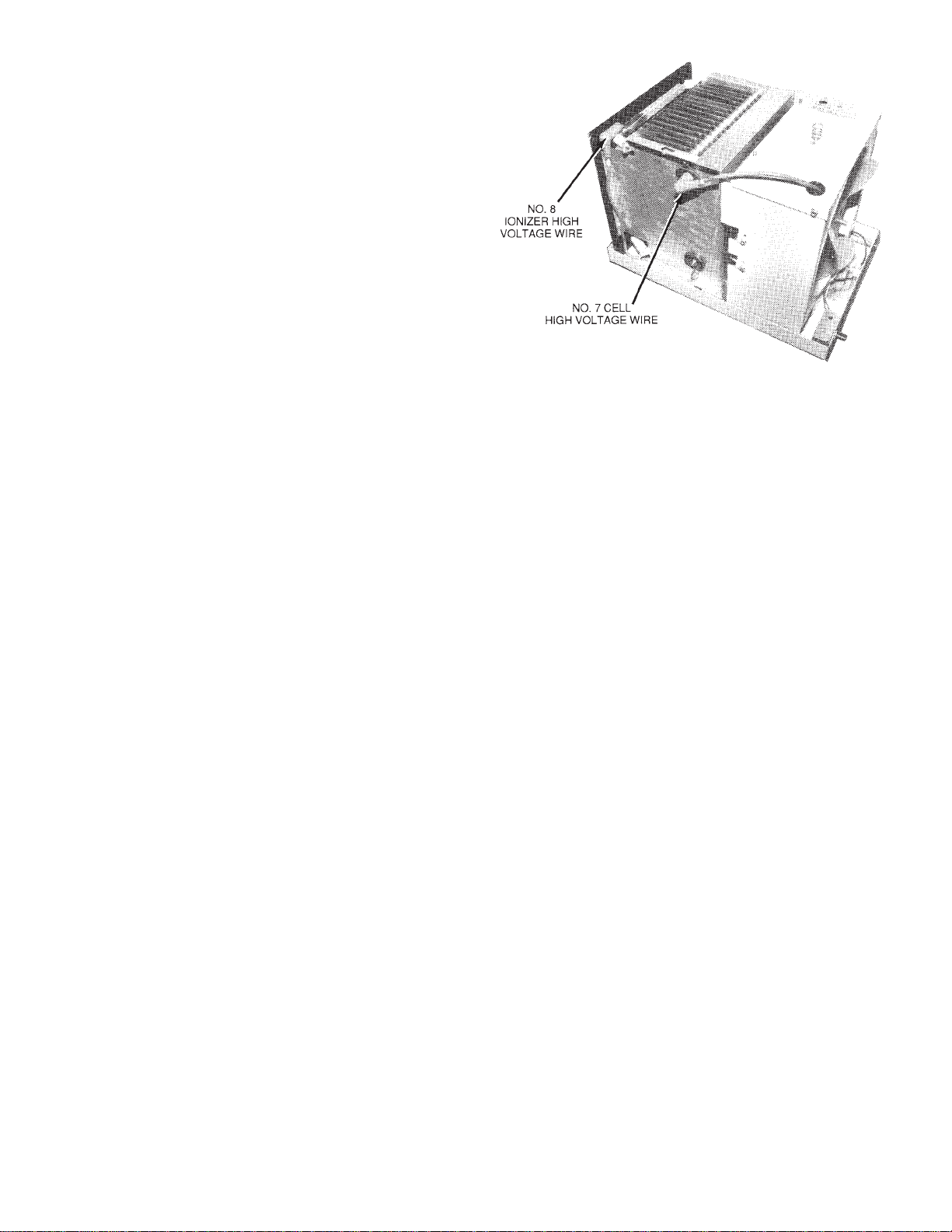
HOW THE HIGH VOLTAGE IS SUPPLIED TO THE
COMPONENTS
The power pack supplies high voltage DC to the
ionizing and collecting sections of the unicell by the
use of high voltage lead wires. Two separate terminals
are used on the output side of the pack. Terminal #8
supplies nominal 11,000 volts DC positive to the ionizer.
Terminal #7 supplies 5,500 volts DC to the cell (see
Figure 4).
TOOLS REQUIRED FOR TROUBLESHOOTING
—Screwdriver — (common type) 8" or longer with in-
sulated handle.
—Volt-Ohm Meter — for measuring low voltage input
(115 VAC), continuity (OHMS) and low voltage DC.
—High Voltage Probe (DC) positive polarity — for
checking the high voltage power supply (minimum
range from 0 to 15 KV DC).
HOW TO MEASURE HIGH VOLTAGE
For accurately measuring the high voltage, a 0 to 15 KV
minimum scale high voltage probe capable of mea-
suring positive polarity is required.
FIGURE 4

7
MEASURING UNICELL IONIZER VOLTAGE
(See Figure 5)
1. Turn the unit off and remove the cabinet. This will
disengage the safety interlock.
2. Connect the ground clip of the positive polarity
probe to the base unit.
CAUTION: Always ground the high voltage probe to
a solid ground connection on the base
unit.
MEASURING UNICELL COLLECTOR VOLTAGE
(See Figure 6)
1. Connect the ground clip of the positive polarity
probe to the base unit.
2. Engage the safety interlock switch and measure the
collector high voltage by placing the probe’s tip on
one of the charged plates. The voltage reading
should be 5.0 to 6.0 KV DC.
3. Turn unit speed control switch on and cautiously
engage the safety interlock switch by depressing
the button.
CAUTION: Be sure to disengage safety interlock
switch after measuring voltages.
4. Place the probe’s tip on the ionizer and measure
the positive DC voltage. The voltage should read
10.0 to 11.0 KV DC.
•If measurements are abnormal, refer to the
troubleshooting guide for cause and correction.
•If measurements are abnormal, refer to the
troubleshooting guide for cause and correction.
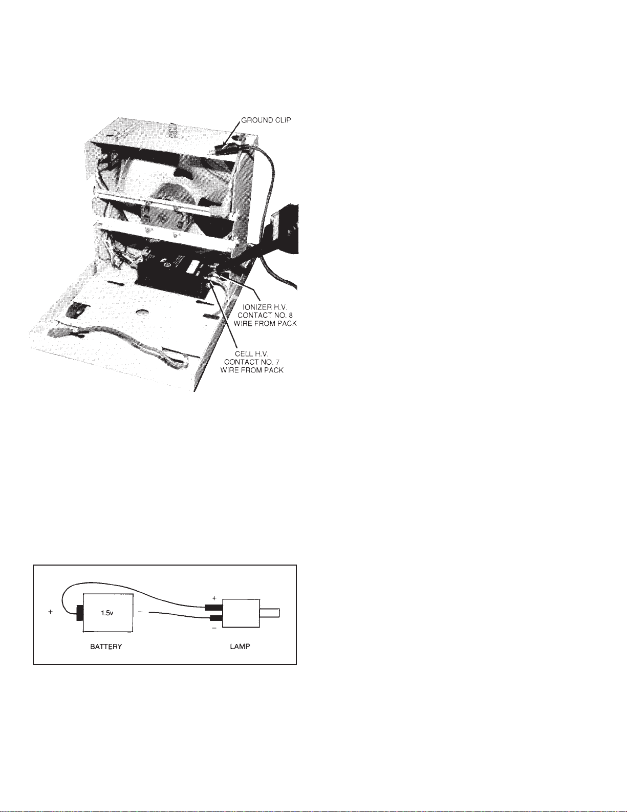
CHECKING THE POWER PACK OUTPUT
(See Figure 7)
1. Remove unicell from the cabinet.
2. Engage the safety interlock switch and measure the
output from the ionizer terminal of the power pack
by placing the probe’s tip on the ionizer high voltage
contact.
•Output reading without the unicell should read 11.0
to 13.0 KV DC positive.
FIGURE 5
FIGURE 6
8
3. To measure the collection cell output voltage, place
the probe’s tip on the cell high voltage contact.
•Output without the unicell should read 5.0 to 6.5 KV
DC positive.
CHECKING LAMP VOLTAGE
1. Check power supply output lamp output by con-
necting a good 2 volt lamp.
2. Check lamp operation with 1.5 volt battery as
shown in Figure 8.
VIII.REPLACEMENT PARTS
Replacement parts can be ordered from your local
distributor or from UAS. To order parts from UAS,
call or write:
UNITED AIR SPECIALISTS, INC.
4440 CREEK ROAD
CINCINNATI, OHIO 45242
1-800-551-5401
ATTN: SMOKEETER/CRYSTAL-AIRE
CUSTOMER SERVICE
The following information will be required for prompt
service:
1. Unit Model No. on bottom of base unit at air
mover end.
2. Unit Serial No. on bottom of base unit at air mover
end.
3. Part No. of part (see Section IX, Illustrated Parts).
When returning a defective part under warranty, you
must call UAS for a customer return authorization
number. This number should appear on the package
that is being returned. With this control number, we can
assure you will receive prompt service. You can also
return defective parts to your local distributor.
FIGURE 7
FIGURE 8

9
TROUBLESHOOTING GUIDE
PROBLEM POSSIBLE CAUSE CORRECTIVE ACTION
A. Control switch on, 1. Defective lamp. 1. Replace lamp.
indicator lamp off, 2. Faulty connection to lamp. 2. Check connection to lamp.
air mover operates. 3. Loss of high voltage. 3. Check power pack.
B. Control switch on, 1. Air mover faulty. 1. Replace air mover.
indicator lamp on, 2. Foreign object locking 2. Clean foreign object from
air mover does not air mover. air mover.
operate. 3. Faulty control switch. 3. Replace control switch.
4. Connector not properly 4. Check connection at
connected (at control control switch.
switch).
C. Control switch on, 1. Unit is not plugged in. 1. Plug unit into 115 VAC
air mover and lamp off. receptacle.
2. Safety interlock switch 2. Engage safety interlock
not engaged. switch.
3. Safety interlock switch 3. Replace safety interlock
defective. switch.
4. Control switch defective. 4. Replace control switch.
D. Air mover operates on 1. Control switch defective. 1. Replace control switch.
low or high speed only.
E. Poor air quality. 1. Unicell dirty. 1. Clean unicell.
2. Unicell malfunctioning. 2. Check unicell for:
a. Foreign matter between
plates
b. Ionizer wire loose or
broken
c. Defects in insulators
3. Unicell installed 3. Install unicell as shown
backwards or upside in Figure 1.
down.
4. High voltage contacts 4. Clean high voltage
dirty. contacts.
5. Unit being operated on 5. Increase air mover speed.
too low a speed.
6. Placement of unit not 6. Contact your local
creating a good air distributor or United Air
pattern. Specialists.
F. High voltage output 1. Loss of input 115 VAC. 1. Determine loss of input
low or zero. voltage.
2. Unicell malfunctioning. 2. Check unicell for:
a. Foreign matter between
plates
b. Ionizer wire loose or
broken
c. Defects in insulators
3. Power pack defective. 3. Replace power pack.
*Refer to Wiring Diagram and Illustrated Parts
10
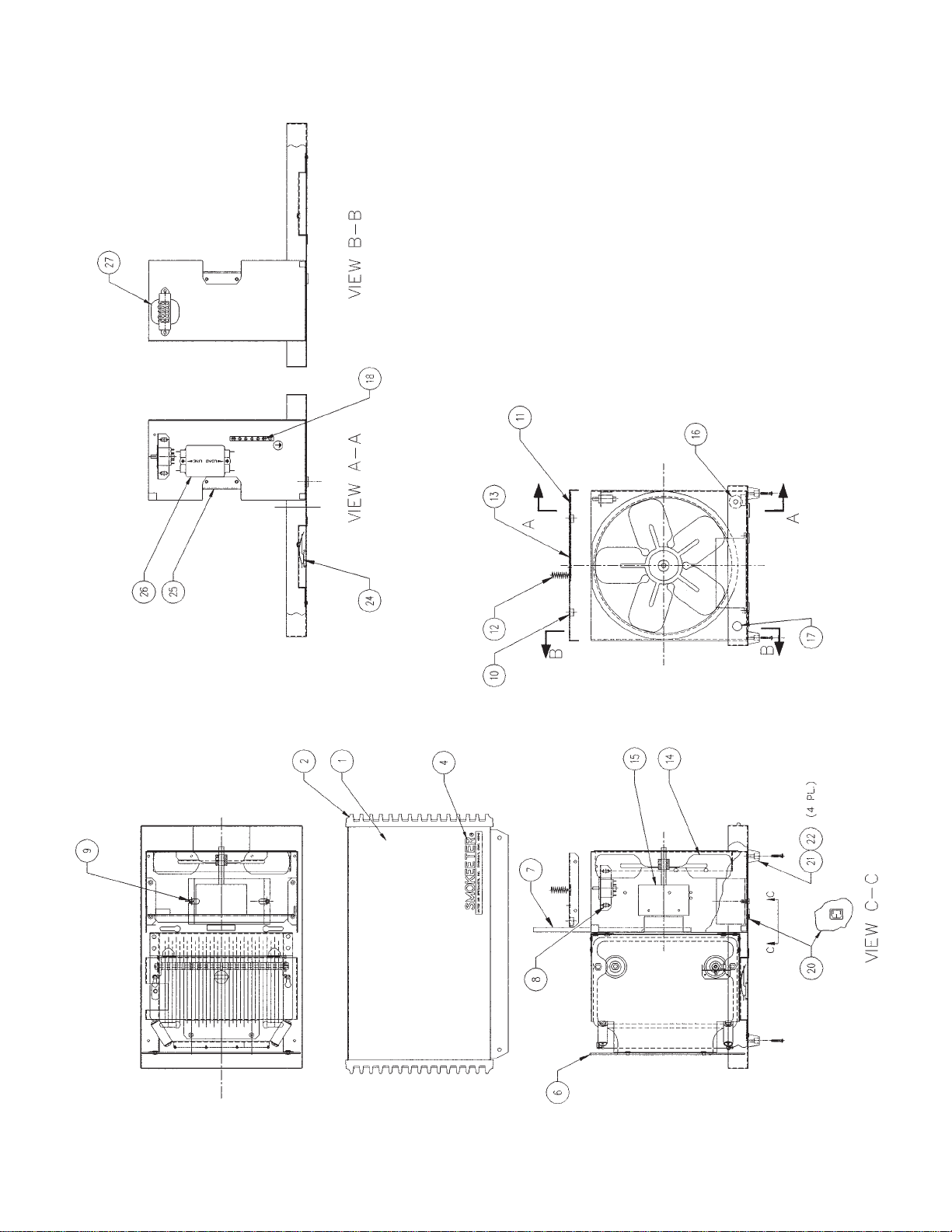
IX. ILLUSTRATED PARTS

11
SE 10 REPLACEMENT PARTS
ITEM NO. PART NO. DESCRIPTION QTY.
1CHOOSE 1 10-8878 WRAPPER, OYSTER 1
10-3048 WRAPPER, WOODGRAIN 1
2CHOOSE 1 33-0136 GRILLE, OYSTER 2
33-0146 GRILLE, BLACK 2
3CHOOSE 1 30-0589 KNOB, OYSTER 2
30-0588 KNOB, BLACK 2
4CHOOSE 1 41-1026 SMOKEETER LOGO, OYSTER 1
41-1130 SMOKEETER LOGO, WOODGRAIN 1
41-1246 CRYSTAL-AIRE LOGO, OYSTER 1
41-1247 CRYSTAL-AIRE LOGO, WOODGRAIN 1
510-2735 PRE-FILTER SCREEN 1
602-2723 UNICELL 1
733-0154 CARBON FILTER 1
820-2841 INTERLOCK SWITCH 1
9CHOOSE 1 21-1219 POWER PACK, 90-130V 1
21-1246 POWER PACK, 200-250V 1
10 30-0537 TINNERMAN NUT 2
11 36-0072 LEAF SPRING, INTERLOCK ACTUATOR 1
12 36-0014 CONTACT SPRING, COIL 1
13 10-3491 FAN COVER 1
14 32-0156 ALUMINUM PROPELLER 1
15 02-2625 MOTOR ASSEMBLY 1
16 20-1314 LED INDICATOR 1
17 CHOOSE 1 03-1513 SPEED CONTROL (VARIABLE SPEED UNITS) 1
20-1421 ROCKER SWITCH (2-SPEED UNITS) 1
18 20-1368 GROUNDBUS 1
19 20-2922 CORD, 10' GREY 1
20 20-2921 IEC 320 CONNECTOR 1
21 30-1735 SCREW, SELF-TAPPING, #10-32X3/4 1
22 39-0286 FOOT, MOLDED 1
23 RESERVED
24 03-1535 CONTACT SPRING 1
25 10-9347 MOTOR BRACKET 1
26 OPTIONAL 25-0229 EMI FILTER 1
27 230 V UNITS 21-1255 TRANSFORMER, 23OV-12OV, IEC APPROVED 1
28 NOT SHOWN 03-0862 HIGH VOLTAGE WIRE KIT 1
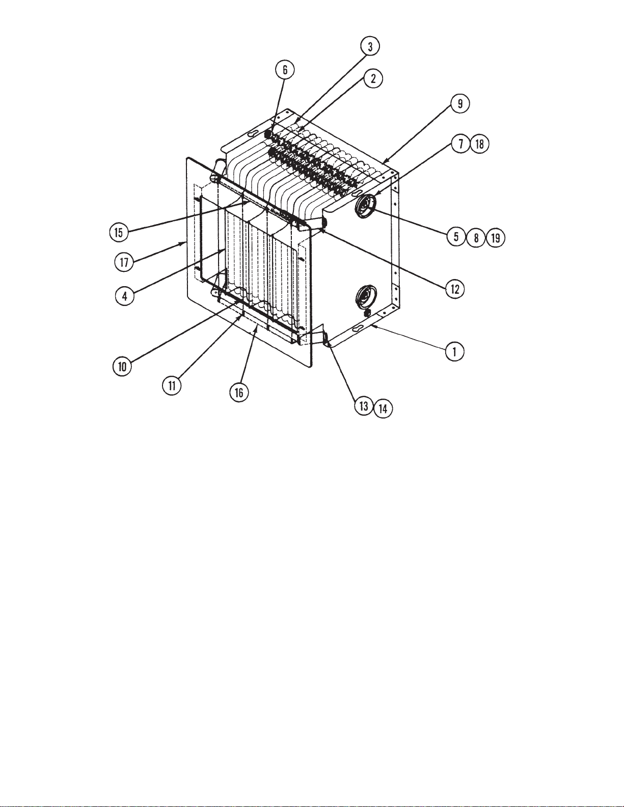
12
SE 10 UNICELL ASSEMBLY
02-2723
ITEM PART
NO. NO. DESCRIPTION QTY.
110-2780 END PLATE 2
210-0946 CELL PLATE, NARROW 16
310-0944 CELL PLATE, WIDE 12
410-2805 IONIZER GROUND PLATE 3
535-0072 CELL ROD 8-15/16" LG 4
635-0067 CELL SPACER 62
737-0008 CELL INSULATOR, DISK 4
830-0449 HEX NUT-1/4-20 8
910-2811 CORNER ANGLE 2
10 02-2721 IONIZER WIRE ASSEMBLY 4
11 36-0037 IONIZER WIRE SPRING 8
12 37-0013 INSULATOR (CERAMIC) 4
13 30-0039 LOCKWASHER #8 INT TOOTH 8
14 30-0119 SCR, PAN HD 8-32x5/16 LG 8
15 18-0795 IONIZER RAIL (TOP, WITH H.V. CONTACT) 1
16 10-2786 IONIZER RAIL (BOTTOM) 1
17 37-0064 UNICELL MASK 1
18 30-0283 CELL SPACER WASHER 4
19 20-1312 TERMINAL, CELL 1
20 20-1313 TERMINAL, IONIZER 1
*To convert cell with “spark plug” type H.V. connections to current H.V. connections, order kit
#03-1595.
13
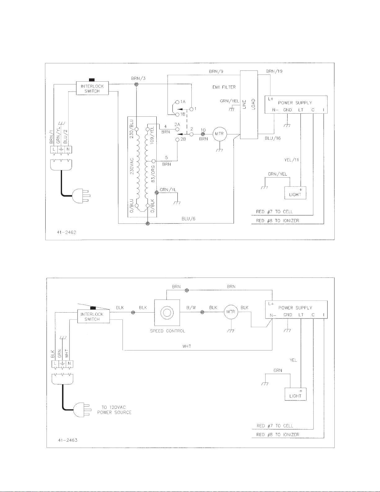
WIRING DIAGRAMS
SE 10 230 VAC, 2-Speed
SE 10 120 VAC,Variable Speed

To Place an order contact ACS, Inc. @ (800) 878-5030
UNITED AIR SPECIALISTS, INC,
LIMITED WARRANTY
UAS warrants all equipment manufactured and sold by UAS against defective parts and
workmanship for one year from date of shipment to Purchaser, except that commercial or
nonindustrial air cleaners (other than engineered systems) are warranted for three years from such
date. This warranty is subject to the limitations in UAS’ standard terms and conditions provided to
Purchaser. Any unauthorized repairs or modifications or abnormal use or misuse of equipment will
void all warranties. In no case will UAS’ responsibility or warranty extend to equipment not
manufactured by UAS.
THE FOREGOING WARRANTY IS EXCLUSIVE AND IN LIEU OF ALL OTHER WARRANTIES,
WHETHER WRITTEN, ORAL OR IMPLIED, INCLUDING ANY IMPLIED WARRANTY OF
MERCHANTABILITY, FITNESS FOR A PARTICULAR PURPOSE OR NONINFRINGEMENT.
As Purchaser’s exclusive remedy for any defects in the equipment, UAS will exchange or repair any
defective parts during the warranty period, provided such parts are returned, prepaid, to UAS’factory.
The obligation of UAS is limited to furnishing replacement parts F.O.B. UAS’ factory or making repairs
at UAS’ factory of any parts which are determined, upon inspection by UAS, to be defective. UAS
is not responsible for labor or transportation charges for the removal, reshipment or reinstallation of
the parts.
IN NO EVENT WILLUAS BE RESPONSIBLE FORANY SPECIALOR CONSEQUENTIAL DAMAGES.
PRINTED IN USA
Part No. 44-2454
8/97
Table of contents
Other Smokeeter Air Cleaner manuals


Popular Air Cleaner manuals by other brands


EcoWays
EcoWays GENESIS Pro manual

Klarwind
Klarwind Klarwind-500s user manual

LUCCI Air
LUCCI Air ALLO manual

Deltech Fitness
Deltech Fitness PYRAMID 8000 Installation, operating and maintenance manual

Suntec Wellness
Suntec Wellness Klimatronic AirCare 200 instruction manual

Heaven Fresh
Heaven Fresh HF 86 instruction manual