SMS TAKEDO-3VF User manual

TAKEDO- 3VF
NXP
For asynchronous motors
or
Permanent Magnets Synchronous
Motors
USER MANUAL
P09.1 137 01-12-2017 R. Bocconi
REV. SOFTWARE DATE R.T. Check and Approval

TAKEDO - 3VF NXP USER MANUAL Release P09.1 dated 01-12-2017
2
A QUICK GUIDE TO PUTTING ON DUTY OPEN LOOP
ASYNCHRONOUS MOTORS (without encoder) Page 3
B QUICK GUIDE TO PUTTING ON DUTY CLOSED LOOP
ASYNCHRONOUS MOTORS (with encoder) Page 4
C QUICK GUIDE TO PUTTING ON DUTY SYNCHRONOUS MOTORS
Page 5
LIST OF CONTENTS
DIRECT ARRIVAL AT FLOOR – ASYNCHRONOUS MOTORS Page
32 Par.
9.1
DIRECT ARRIVAL AT FLOOR – SYNCHRONOUS MOTORS Page
42 Par.
13.2
IDENTIFICATION (OPEN LOOP) Page
21 Par.
6.4
SAFETY WARNINGS Page
9 Par.
2.1
PRECAUTIONS Page
10 Par.
2.2
POWER CONNECTION Page
10 Par.
3
ELECTROMAGNETIC COMPATIBILITY (EMC) Page
12 Par.
3.2
CABLE BENDING MEASUREMENT Page
21 Par.
6.6.2
STARTUP TORQUE Page
22 Par.
6.6.3
ONE FLOOR TRAVEL – ASYNCHRONOUS MOTORS Page
25 Par.
6.8
ONE FLOOR TRAVEL – SYNCHRONOUS MOTORS Page
42 Par.
13.1
VACON EC CONFORMITY DECLARATION Page
50
EMERGENCY Page
26 Par.
6.10
ENCODER FOR ASYNCHRONOUS MOTORS Page
29 Par.
8
ENCODER FOR SYNCHRONOUS MOTORS Page
37 Par.
11
ACTIVE FAULTS AND ALARMS Page
16 Par.
5.4
POWER LIMIT Page
21 Par.
6.6.1
MAINTENANCE Page
27 Par.
7
FAULT HISTORY Page
19 Par.
5.5
SYSTEM MENU Page
19 Par.
5.6
PUTTING ON DUTY SYNCHRONOUS MOTORS Page
39 Par.
12
MONITOR Page
16 Par.
5.1
CLOSED LOOP ASYNCHRONOUS MOTORS Page
28
SYNCHRONOUS MOTORS Page
35
PARAMETERS Page
45 Par.
14
SPECIAL PARAMETERS – CLOSED LOOP ASYNCHRONOUS MOTORS Page
34 Par.
9.2
SPECIAL PARAMETERS – SYNCHRONOUS MOTORS Page
44 Par.
13.3
LOAD CELL Page
22 Par.
6.6.3
OPEN LOOP ADJUSTMENTS Page
24 Par.
6.7
CLOSED LOOP ADJUSTMENTS Page
31 Par.
9
SYNCHRONOUS MOTORS SETTINGS Page
41 Par.
13
PRELIMINARY ADJUSTMENTS Page
20 Par.
6.1 - 6.3
BRAKING RESISTOR Page
10 Par.
3.1
MOTOR NOISE Page
25 Par.
6.9
SAFETY GEAR UNLOCKING Page
23 Par.
6.6.4
EXPANSION BOARDS Page
19 Par.
5.7
APPLICATION DIAGR. FOR ASYNCHRONOUS MOTOR WITHOUT ENABLE Page
13 Par.
4.1
APPLICATION DIAGR. FOR ASYNCHRONOUS MOTOR WITH ENABLE Page
14 Par.
4.2
APPLICATION DIAGR. FOR SYNCHRONOUS MOTOR Page
36 Par.
10
INVERTER SELECTION GUIDE Page
11
KEYPAD AND MENU Page
15 Par.
5
FAN CONTROL Page
21 Par.
6.5

TAKEDO - 3VF NXP USER MANUAL Release P09.1 dated 01-12-2017
3
A
QUICK GUIDE TO PUTTING ON DUTY
OPEN LOOP ASYNCHRONOUS MOTORS
(without encoder)
1) Make all connections as indicated in the manual.
2) Check the following parameters:
Parameter
Description
Unit
SMS setting
Value to be set
Value
S6.1 Language Italian Select according to
country of use
S6.2 Application AsynchMotor AsynchMotor
3) Enter data in the following parameters:
Parameter
Description
Unit
SMS setting
Value to be set
Value
P2.1.2 Motor Nominal Voltage V 400 Motor rating plate data
P2.1.3 Motor Nominal Frequency Hz 50 Motor rating plate data
P2.1.4 Motor Nominal Speed RPM 1440 Motor rating plate data
P2.1.5 Motor Nominal Current A I Inverter Motor rating plate data
P2.1.6 Motor Cos Phi 0.82 Motor rating plate data
P2.1.7.1 Lift Rated Speed m/sec 0.70 LIFT data
P2.1.7.2 Pulley Diameter mm 520
LIFT data
P2.1.7.3 Gear Ratio 1.58
LIFT data
P2.1.7.4 Ropes Ratio 1:1 LIFT data
P2.1.7.5 Update Data No Yes
4)
Run IDENTIFICATION Routine
:
- Set parameter P2.1.8 to “ID No Run” and make a call command: the contactors energizes, the brake
doesn’t open, and “RUN” lights up.
- When the “RUN” light goes off, “STOP” appears and parameter P2.1.8 automatically turns to “No
Action”, deactivate the call (e.g. by opening the operation valve).
5) If it does not work perfectly, see the full MANUAL.

TAKEDO - 3VF NXP USER MANUAL Release P09.1 dated 01-12-2017
4
B
QUICK GUIDE TO PUTTING ON DUTY
CLOSED LOOP ASYNCHRONOUS MOTORS
(with encoder)
1) Make all connections as indicated in the manual.
2) Check the following parameters:
Parameter
Description
Unit
SMS setting
Value to be set
Value
S6.1 Language Italian Select according to
country of use
S6.2 Application AsynchMotor AsynchMotor
3) Enter data in the following parameters:
Parameter
Description
Unit
SMS setting
Value to be set
Value
P2.1.2 Motor Nominal Voltage V 400 Motor rating plate data
P2.1.3 Motor Nominal Frequency Hz 50 Motor rating plate data
P2.1.4 Motor Nominal Speed RPM 1440 Motor rating plate data
P2.1.5 Motor Nominal Current A I Inverter Motor rating plate data
P2.1.6 Motor Cos Phi m/sec 0.82 Motor rating plate data
P2.1.7.1 Lift Rated Speed m/sec 0.70 LIFT data
P2.1.7.2 Pulley Diameter mm 520
LIFT data
P2.1.7.3 Gear Ratio 1.58
LIFT data
P2.1.7.4 Ropes Ratio 1:1 LIFT data
P2.1.7.5 Update Data No Yes
P2.1.12 Encoder Type Incremental Incremental
P2.1.13 Encoder Direction Not inverted
Not inverted
if motor is going up
Inverted
if motor is going up
P2.5.1 Motor Control Mode Open loop Closed Loop
P2.5.4.1 Magnetizing Current A 0.5 * I Inverter
If unknown:
-
for 1/2 speed motors for
lifts, enter
1/3 of value in P2.1.5
-
for motors with inverters,
enter
2/3 of value in P2.1.5
P7.3.1.1 Pulse/revolution
(Number of encoder pulses) 1024
Number of pulses /
revolution of installed
encoder
4) If it does not work perfectly, see the full MANUAL.
5) For other accessory functions such as POWER LIMIT, ONE FLOOR TRAVEL ONLY, DIRECT FLOOR
ARRIVAL etc. see the full manual.

TAKEDO - 3VF NXP USER MANUAL Release P09.1 dated 01-12-2017
5
C
QUICK GUIDE TO PUTTING ON DUTY
PERMANENT MAGNET SYNCHRONOUS MOTORS
FREE MOTOR, NO CABLES
1 – BRAKE AND BRAKE CONTROL MICRO-SWITCH CONNECTION
(see TAKEDO-3VF NXP Manual and the Amendment 3)
R = 1,2kΩ1/4W

TAKEDO - 3VF NXP USER MANUAL Release P09.1 dated 01-12-2017
6
2 –
MOTOR AND ENCODER CONNECTION
(MAKE EARTH CONNECTIONS AS SHOWN IN THE PHOTOS)
12.9
12.9

TAKEDO - 3VF NXP USER MANUAL Release P09.1 dated 01-12-2017
7
3) Check the following parameters:
Parameter
Description
Unit
SMS setting
Value to be set
Value
S6.1.2 Language Italian Select according to
country of
S6.2.2 Application AsynchMotor PermMagnSync
4) Enter data in the following parameters:
Parameter
Description
Unit
SMS setting
Value to be set
Value
P2.1.2 Motor Nominal Voltage V 400 Motor rating plate data
P2.1.3 Motor Nominal Frequency Hz 8.00 Motor rating plate data
P2.1.4 Motor Nominal Speed RPM 60 Motor rating plate data
P2.1.5 Motor Nominal Current A I Inverter Motor rating plate data
P2.1.6 Motor Cos Phi 0.90 Motor rating plate data
P2.1.7.1 Lift Rated Speed m/sec 1.00 LIFT data
P2.1.7.2 Pulley Diameter mm 320 LIFT data
P2.1.7.3 Gear Ratio 1.01 LIFT data
P2.1.7.4 Ropes Ratio 1:1 LIFT data
P2.1.7.5 Update Data No Yes
P2.1.12 Encoder Type Incremental Encoder Type:
Incremental or EnDat
P2.1.13 Encoder Direction Not inverted
Not inverted
if motor is going up
Inverted
if motor is going up
P2.1.14 Calculated Poles 0
Make sure the number of
poles calculated
matches
the number for the motor
P2.1.16 Motor Rs 0 If motor rating is
unknown, leave at 0
P2.1.17 Motor Xs 0 If motor rating is
unknown, leave at 0
P7.3.1.1 Pulse/revolution
(Number of encoder pulses) 2048
Number of pulses /
revolution of installed
encoder
5) If the encoder is an EnDat type, follow the procedure illustrated in paragraph 12.9 A) of the full MANUAL
step by step.
6) If the encoder is an incremental type, follow the procedure illustrated in paragraph 12.9 B) of the full
MANUAL step by step.
7) If it does not work perfectly, see the full MANUAL.
8) For other accessory functions such as POWER LIMIT, ONE FLOOR TRAVEL ONLY, DIRECT FLOOR
ARRIVAL etc. see the full manual.

TAKEDO - 3VF NXP USER MANUAL Release P09.1 dated 01-12-2017
8
INTENTIONALLY BLANK PAGE

TAKEDO - 3VF NXP USER MANUAL Release P09.1 dated 01-12-2017
9
1 – INTRODUCTION
The TAKEDO–3VF NXP is an inverter drive with built-in EMC filter and smoothing choke, responding to
Council Directives 3/89/CEE (electromagnetic compatibility) 336/73/CEE (low voltage equipment).
To ensure compliance with EN12015 regarding low frequency harmonics, a further 3% inductance is
required.
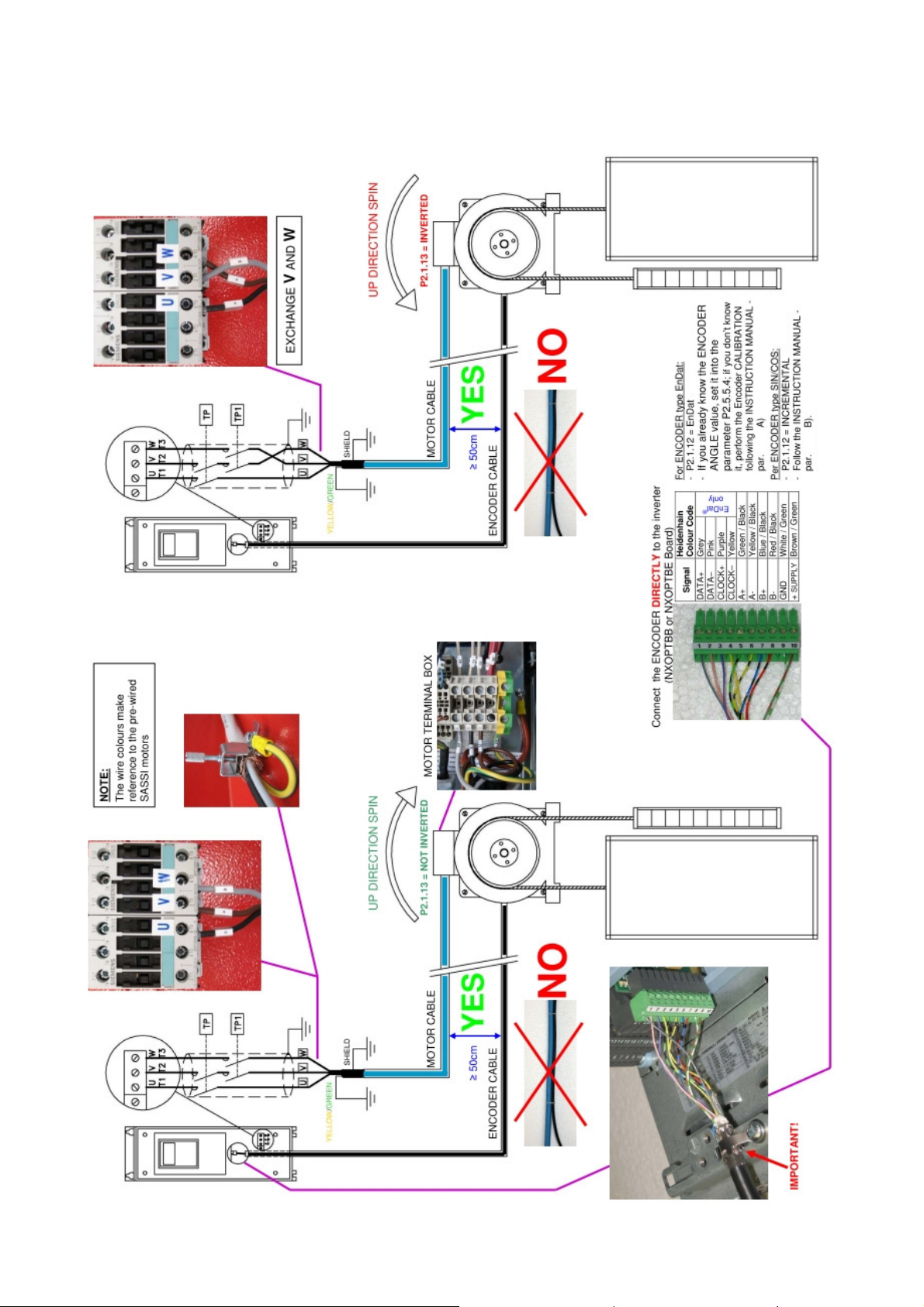
The drive can operate both in open loop and closed loop modes. For operation in closed loop mode, an
optional circuit board is required, and an encoder as described in the following pages.
This manual provides you with the necessary information about the starting up and operation of the NXP
frequency converter. You can find further information about application and installation in a lift control panel
in the ANNEX NXP FOR PANEL WIRING SPECIALISTS , available in electronic edition on our website:
www.sms.bo.it.
2 – SAFETY WARNINGS AND PRECAUTIONS
Full details are available in the original VACON manual (NXP range inverters) which can be consulted
at www.it.vacon.com.
Read this manual in its entirety before powering up the equipment, following the procedures step by step. In
detail, please read the following chapters carefully:
5.4 – ACTIVE FAULTS AND ALARMS
6 – ADJUSTMENT PROCEDURE
2.1 SAFETY WARNINGS
Follow the procedures indicated below with due care, so as to avoid any risk of serious accident.
1- The leakage current from the inverter to ground is greater than 30mA, and accordingly, the power
circuit must incorporate a differential circuit breaker with Id not less than 300mA, type B or type A
(type B is preferable). Under European directives, the ground connection must use a cable of not less
than 10 mm² section.
2- If the parameters used to program the drive are incorrect, the motor may rotate faster than synchronous
speed. Do not run the motor beyond its specified electrical and mechanical limits. The installer is
responsible for ensuring that movements are generated in conditions of safety, without exceeding
specified operating limits.
3- Risk of electrocution. Power up the inverter only with the front cover fitted. NEVER remove the cover
during operation. Before carrying out any operation on the equipment, isolate from the electrical power
supply and wait a few minutes for the internal capacitors to discharge.
4- The external braking resistor heats up during operation. Do not install it close to or in contact with
inflammable materials. To improve heat dissipation it is good practice to fix the resistor to a metal plate.
Ensure it is properly protected and cannot be touched.
5- The inverter must always be connected to the mains supply. In case of interruption wait 1 minute at
least before restoring the supply. TOO NEAR INSERTIONS OF THE MAINS CAN CAUSE A
PERMANENT DAMAGE OF THE INVERTER
2.2 PRECAUTIONS
Follow the procedures indicated in the manual with care so as to avoid the risk of damaging or destroying the
drive.
1- Do not connect the equipment to a voltage higher than the permissible input voltage. An excessive
voltage can cause irreparable damage to internal components.
2- Check the fan regularly: check the air flow is constant and remove and built-up dust.
3- To avoid the risk of damaging the drive in case it stays not working without power supply for a
long time, you should follow these precautions:
- If the inverter doesn’t work since several months, before starting the operation, regenerate the
bus capacitors powering up the drive at least for 1 hour preventing it can operate.
- If the inverter doesn’t work since one year or more, to regenerate the bus capacitors power up
the drive, preventing it can operate, for 1 hour at an input voltage less than 50% the rated
voltage, then for 1 hour at the rated input voltage.
4- Do not connect capacitors to the inverter outputs.
5- If the drive protection functions trip, do not reset the fault before having analysed and removed the
cause of the fault.
6- The lift system should be counterweighted at 50%, if counterweighted at 40% the current in up direction
with full load is greater and requires a larger capacity inverter to that normally necessary, with
consequent greater cost.
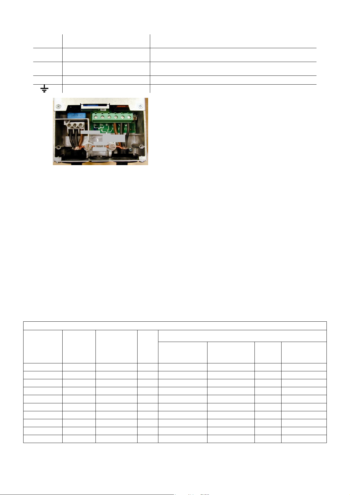
7- Use a drive having rated current equal to or greater than the motor rated current .
8- The braking resistor have to be connected between B+ and R-.
If connected between B+ and B-, the inverter will be permanently damaged.

TAKEDO - 3VF NXP USER MANUAL Release P09.1 dated 01-12-2017
10
3 – CONNECTING THE POWER CIRCUIT
L1;L2;L3 A.C. mains power input Connect the three phases of the power supply to any three
terminals, in any order
L1;L2 D.C. power input Connect the batteries in the event of emergency operation
(evacuation)
U;V;W Inverter output Connect the three output phases to the contactors, then to the
motor.
B+;R- External braking resistor Connect the external braking resistor
Ground Connect to the ground system
Exa example of power circuit connection
3.1 SAFETY WARNINGS
1- Ground the unit before powering it.
2- To increase the protection of the internal diodes and connecting wires (especially against the
overvoltage due for example to atmospheric phenomena), you should connect three fast-acting fuses
(one for each phase) in series with the a.c. power input terminals; fuses must be rated to match the
different size designations as indicated in
TABLE – Recommended braking resistors and fuses.
The fuse kit, complete with box, is available on request.
3- To avoid irreparable damage to the inverter, do not connect braking resistors with resistance or
power ratings lower than those indicated in TABLE. For long run lifts or high reverse gain gears,
install the braking resistor with oversized power but with the same value in ohms (if needed, contact
SMS for advice!).
4- The inverter drive is connected <<up line>> of the power contactors. The drive is able to pilot operation
of the motor in two directions, accordingly, the system can incorporate only two power contactors to
switch the inverter – motor line, as prescribed in safety regulations.
5- The external braking resistor heats up during operation. Do not install it close to or in contact with
inflammable materials. Ensure it is properly protected and cannot be touched.
6- Wire and bond ground connections in accordance with professional standards (as indicated under
heading 3.2) to avoid problems with EMC interference.
7- Take particular care over the power connections. If the input and output connections are reversed, the
inverter will be inevitably damaged.
INVERTER 400 VOLT (380-500V) SERIES
MOTOR
RATED
CURRENT
(A)
CODE
DIMENSIONS
LxHxW
(mm)
FAST
ACTING
FUSES (A)
BRAKING RESISTOR
SUPPLIED BY
SMS
(Geared motor)
SUPPLIED BY
SMS
(Gearless motor)
MINIMUM
VALUE
(Ω
ΩΩ
Ω)
DIMENSIONS
LxWxH (mm)
14 TKP00145 128x292x190 16 Ask SMS 50Ω1500W
42Ω445x110x140
20 TKP00205 144x391x214 35 Ask SMS 2x50Ω1500W
42Ω445x110x140(*)
27 TKP00275 144x391x214 35 Ask SMS 2x50Ω1500W
21Ω445x110x140(*)
35 TKP00355 195x519x237 50 Ask SMS 2x50Ω1500W
21Ω445x110x140(*)
46 TKP00465 195x519x237
63 Ask SMS 3x50Ω1500W
14Ω445x110x140(*)
61 TKP00615 237x591x257 80 4x50Ω1500W
4x50Ω1500W
6,5Ω445x110x140(*)
72 TKP00725 237x591x257 100 5x50Ω1500W
5x50Ω1500W
6,5Ω445x110x140(*)
87 TKP00875 237x591x257 125 8x50Ω1500W
8x50Ω1500W
6,5Ω
445x110x140(*)
105 TKP01055 291x758x344 160 10x50Ω1500W
10x50Ω1500W
3,3Ω
445x110x140(*)
140 TKP01405 291x758x344 200 12x50Ω1500W
12x50Ω1500W
3,3Ω
445x110x140(*)
(**)
Full dimension is the one indicated multiplied by the number of resistors.
TABLE – Fuses and recommended braking resistors
For higher powers and voltages, or advice on application, contact SMS.
Mains cable
Motor cable
CC
Braking
resistor
Groun
d
terminal

TAKEDO - 3VF NXP USER MANUAL Release P09.1 dated 01-12-2017
11
IMPORTANT: For high travel (>30m) or gear with high inverse efficiency, install the braking resistor
recommended as value in ohm, but power corresponding to the next higher size,
or install the TAKEDO ENERGY, which allows for the regeneration of the energy
dissipated by the braking resistor, with subsequent energy saving.
IMPORTANT:
In case of motor operating frequency lower than 25Hz, the motor nominal current which can be applied
must be derated according to the following GIUDE TABLE.
INVERTER SELECTION GUIDE

TAKEDO - 3VF NXP USER MANUAL Release P09.1 dated 01-12-2017
12
(b)(a)
3.2 INVERTER/MOTOR CABLING RULES TO ASSURE EMC CONFORMITY
The correct INVERTER – MOTOR cabling must follow the rules below:
1- The building ground plant must be connected to both the inverter and motor.
2- The inverter/contactor and contactor/motor cable runs must be as short as possible, shielded with four
poles (three phases plus yellow/green ground wire), or four unshielded wires bound together running in a
duct or grounded metal tube. In other words, in the same cable or tube there must be a ground wire
running as close as possible to the power cables. In the case of a shielded cable the shield must be
unbroken between the inverter/contactor and contactor/motor.
The shield have to be grounded at both ends with a 360°clamp (Fig. 1), or with special terminals
If the shield cannot be grounded with a 360°clamp on the motor terminal block itself, the shield must be
grounded on the motor casing before the cable enters the terminal box.
3- Use a shielded cable also for the inverter input power line to avoid radiated EMC emissions in the system.
The mains input power cables and inverter output cables MUST NOT be run in the same duct and their
runs must be as far apart as possible (at least 50 cm. 50 cm.).
4- The power and control cables must be run as far apart as possible and not parallel to each other, even if
they are shielded; if the cable runs cross they must do so at an angle of 90°.
5- Independently of the connection to the building grounding plant, the motor casing MUST be connected
both to the cable shield and to the yellow/green ground wire inside the shielded cable.
6- The inverter emits electromagnetic radiation which can be captured and transmitted by cables, in
particular by the flexible cables in the shaft.
To avoid this problem, use shielded cables for the control panel logic / inverter connections, with the
shield grounded at both ends. DO NOT use shielded cables without grounding the shields: this leads to
higher levels of EMC disturbance than if unshielded cables are used. Any wire in a multi-pole cable
which is not in use must be grounded at both ends .
7- Any cable, whether control and external shaft or car connections, must never run parallel/near to the
power cable, even if shielded; if they must be parallel for any reason, they should be run through separate
metal ducts.
8- The pulse generator cable must be shielded and the shield grounded at the inverter end, as far as
possible from the motor cable. The motor/pulse generator coupling must be isolated to avoid parasitic
currents looping through the pulse generator. As for all other shields, the ground connection must be via a
360°clamp.
9- All ground connections should be as short as possible and wide .
Copper braid (a) is better than wire (b).
10-
To avoid unintentional tripping of the differential circuit breakers take the following steps:
make the power cable runs as short as possible.
Use circuit breakers designed for harmonics (type B or type A, with tripping current 300mA).
Reduce the inverter carrier frequency (if possible); the lower the frequency the noisier the motor will be
but the smaller the grounding currents and EMC phenomena; motor windings will be less stressed.
SHEATH
ASSEMBLY PANEL
SHIELD
OMEGA CONNECTOR
UNPAINTED AREA

TAKEDO - 3VF NXP USER MANUAL Release P09.1 dated 01-12-2017
13
4 – BASIC APPLICATION DIAGRAMS
N.B.: THE FILTER AND REACTANCE ARE
INSTALLED INSIDE THE INVERTER.
TO ENSURE OPTIMUM EMC COMPATIBILITY,
INPUT AND OUTPUT CABLES MUST BE
SHIELDED.
TAKEDO 3VF
NXP
U
A-
A+
B-
B+ 3
10
9
14
20
19
L2
W
V
22
23
26
25
8
16
15
TP1
LOW SPEED
INSPECTION SPEED
UP
HIGH SPEED
+24Vdc
I<250mA
-
1
2
4
L1
TP
SHIELDED
CABLE
CONTACTORSI
3 – PHASE
LINE
OPEN COLLECTOR OUTPUT
I<50mA D.C. ; V=24 Vdc
CONTCTOR OFF COMMAND
or SPEED DETECTOR
Programmable through par. 2.7.1
(Default = MOTOR SWITCH)
M
3-PH
SHIELDED
CABLE
EARTH CABLE
SHIELDED CABLE
SHIELDED CABLE
SHIELDED CABLE
YELOW
NOTE 1: ENCODER BOARD IS NOT PRESENT
IN OPEN LOOP VERSION.
NOTE 2: CABLE COLOURS REFER TO
LIKA I58H ENCODER
–
OPERATION
BRAKING
RESISTOR
+
OPERATION
RO2
RO1
NXOPTA2
BOARD
FAULT RELAY
Imax<400mA ; Vmax<=125 Vdc
DOWN
+
L3
6
R-
B+
(OPTION)
ENCODER
BOARD
NXOPTA4
(LIine driver)
or
NXOPTA5
(Push-pull)
S
T
R
SHIELDED CABLE
TP
TP1
SHIELDED CABLE
12
18
(
-
)
TB BRAKE CONTACTOR
Imax<400mA ; Vmax<=125 Vdc
DO1
(+)
9
7(GND)
NXOPTA1
BOARD
SHIELDED CABLE
RED
GREEN
BLUE
ORANGE
BLACK
4.1
–
ASYNCHRONOUS MOTOR
WITHOUT
ENABLE LOGIC
B-
TAKEDO
ENERGY
(OPTION)

TAKEDO - 3VF NXP USER MANUAL Release P09.1 dated 01-12-2017
14
N.B.: THE FILTER AND REACTANCE ARE
INSTALLED INSIDE THE INVERTER.
TO ENSURE OPTIMUM EMC COMPATIBILITY,
INPUT AND OUTPUT CABLES MUST BE
SHIELDED.
TAKEDO 3VF
NXP
U
A-
A+
B-
B+ 3
10
9
14
20
19
L2
W
V
23
22
26
25
8
16
15
TP1
LOW SPEED
INSPECTION SPEED
UP
HIGH SPEED
+24Vdc
I<250mA
-
1
2
4
L1
TP
SHIELDED
CABLE
CONTACTORS
3 – PHASE
LINE
OPEN COLLECTOR OUTPUT
I<50mA D.C. ; V=24 Vdc
CONTCTOR OFF COMMAND
or SPEED DETECTOR
Programmable through par. 2.7.1
(Default = MOTOR SWITCH)
M
3-PH
SHIELDED
CABLE
EARTH CABLE
SHIELDED CABLE
SHIELDED CABLE
YELLOW
NOTE 1: ENCODER BOARD IS NOT PRESENT
IN OPEN LOOP VERSION.
NOTE 2: CABLE COLOURS REFER TO
LIKA I58H ENCODER
–
OPERATION
BRAKING
RESISTOR
+
OPERATION
RO2
RO1
NXOPTA3
BOARD
FAULT RELAY
Imax<400mA ; Vmax<=125 Vdc
DOWN
+
L3
6
R-
B+
(OPTION)
ENCODER
BOARD
NXOPTA4
(LIine driver)
or
NXOPTA5
(Push-pull)
S
T
R
SHIELDED CABLE
SHIELDED CABLE
12
18
(
-
)
TB BRAKE CONTACTOR
Imax<400mA ; Vmax<=125 Vdc
DO1
(+)
9
7(GND)
NXOPTA1
BOARD
SHIELDED CABLE
RED
GREEN
BLUE
ORANGE
BLACK
4.2
–
ASYNCHRONOUS MOTOR
WITH
ENABLE LOGIC
AND
BRAKE MICRO CONTROL IN COMPLIANCE WITH AMENDMENT
3
B-
TAKEDO
ENERGY
(OPTION)
TP
TP1
2
4
3
5
BRAKE MICRO 2
BRAKE MICRO 1
R = 1K2
Ω1/4W
R
28
29

TAKEDO - 3VF NXP USER MANUAL Release P09.1 dated 01-12-2017
15
5 – KEYPAD AND PROGRAMMING
The control and programming keypad is included in the TAKEDO-3VF NXP. For the instructions for
use, please refer to the original Vacon manual, available on the website: www.vacon.com.
Sub-menus are accessible from the main menu using the key. The Mon the first line of the text indicates
the main menu. It is followed by a number designating the relative sub-menu. The arrow (→
→→
→)in the bottom
right corner of the display indicates an additional sub-menu that can be retrieved by pressing
the key. To go back to the main menu from the sub-menu, just press the key.
Data are split into menus and submenus on the keypad. Each main menu has seven levels M1 - M7.
Press the or keys to go to another menu.
M1=Monitor M5=Fault History
M2=Parameters M6=System Menu
M4=Active Faults M7=Expander Boards
Each menu contains submenus, which can also be on several levels. To access the submenus, press
the key, then use the +/- keys to show the various quantities; to quit the submenu, press the key.
KEY TO SYMBOLS CONTAINED IN MENUS AND SUBMENUS:
M= Menu (internal modes G,V,P,H,F) V= Read only
G= Group (internal modes V,P) H= Fault history
P= Modifiable parameter F= Active faults
5.0 COPYING PARAMETERS USING THE KEYPAD
The programming keypad can also be used to copy parameters to or from the inverter. This function is very
useful when you need to transfer the optimal parameter set found for a lift on another lift of the same
type, but YOU CAN ONLY USE IT TO COPY PARAMETERS BETWEEN INVERTERS EQUIPPED WITH
THE SAME APPLICATION SOFTWARE RELEASE (the Application software release is written on a label
under the keypad).
5.0.1 – COPYING FROM INVERTER TO KEYPAD
Press the left arrow until "M" appears in the top left followed by the menu number (eg. M2).
Press the up or down arrow keys to reach M6. Follow the instructions on the display:
5.0.2 – COPYING FROM KEYPAD TO INVERTER
The same method as described above applies.
Selecting S6.3.3 instead of S6.3.2 results in "From the panel" instead of "To the Panel" being shown on the
display. Then continue as before.
Note: During the copy from keypad to inverter some data copy will appear as “Locked” . This happens
because there are fixed parameters that are not modifiable (reserved). If the Enter key is pressed at
any time, “Locked” appears (about 6-7 times), copy continues and “OK” will be displayed.
Attention: Copy from a keypad when its data comes from an inverter of the same size of the one you
are copying into.
Connecting the keypad to the inverter in which you want to copy the data , it will appear:
M6
System menu
S1>S8
→
S6.1 appears when you
press the right
arrow.Press the up arrow
until you reach S6.3.
S6.3
TransferParam
P1>P4
→
S6.3.1 appears when you
press the right arrow.
Press the up arrow until
you reach S6.3.2.
S6.3.2
To Panel
Select
→
Press the right arrow.
S6.3.2
To Panel
AllParameters
Press enter to start
copying parameters.
S6.3.2
To Panel
Wait .....
Wait for copying to
complete.
S6.3.2
To Panel
OK
Copying complete. The
control panel now
contains the inverter data.
Copy To Panel?
enter/reset
Push RESET because
you want to copy the
control panel data to
the inverter.
Copy From
Panel?
enter/reset
Press ENTER to start
copying then wait.

TAKEDO - 3VF NXP USER MANUAL Release P09.1 dated 01-12-2017
16
6.1 M1 = MONITOR
This menu displays values and data during inverter operation and it is split into 4 different sub-menus. The
caption V1→
→→
→Vn appears under the name of the menu. This means ‘n’ quantities can be monitored.
Contents
Description
Content
s
Description
G1.1 Drive – Motor
V1.1.1 Output frequency V1.1.8 DC-link Voltage
V1.1.2 FreqReference V1.1.9 Unit temperature
V1.1.3 Motor Speed V1.1.10
Advan Cont Memory
V1.1.4 Motor Torque V1.1.11
Motor Power (absorbed)
V1.1.5 Motor power V1.1.12
Overload Number
V1.1.6 Motor Current V1.1.13
Current Limit Number
V1.1.7 Motor Voltage
G1.2 Input – Output
V1.2.1 DIN1 DIN2 DIN3
Up Down Emergency V1.2.4
Programmable outputs:
DO1 R01 R02
Contactors Fault Brake
V1.2.2 DIN4 DIN5 DIN6
High Low Inspection V1.2.5
NXOPTB5 board programmable outputs:
RE1 RE2 RE3
Contactors Motor Block Speed Detector
V1.2.3
with
NXOPTA2
board
DIN7 DIN8
Run Enable Micro Brake
(term. 2) (term. 4)
V1.2.6 Analog output / Analog Iout
V1.2.3
with
NXOPTA3
board
DIN7 DIN8 DIN9
Brake Micro 2 Brake Micro 1 Run Enable
(term. 2) (term. 4) (term. 28-29/A3)
G1.3 Ride Values
V1.3.1 Lift Speed m/s V1.3.5 LowSpeedDistan (mm)
(Low speed distance)
V1.3.2 Encoder Freq (Hz)
(+ upward, - downward) V1.3.6 FinalStopDistan (mm)
(Stop distance)
V1.3.3 TotalStopDistan (mm) V1.3.7 Total Rope Rides
V1.3.4 Slowing Distan (mm)
(Slowing-down distance) V1.3.8 Partial Rope Rides
G1.4 Braking A3
V1.4.1 Braking Space (mm)
V1.4.2 Mechanical Braking Space (mm)
V1.4.3 Steady Lift Space (mm)
Another very useful display is in menu M6 - S6.11.1 = POWER MULTI-MONITOR - pressing this key
displays motor current for each phase.
5.2 M2 = PARAMETERS
Full list of parameters with associated descriptions is in the paragraph “14 – PARAMETERS LIST”.
5.4 M4 = ACTIVE FAULTS AND WARNINGS
Listed below are the most common fault messages. Be careful not to reset the alarm or fault without first
having investigated the problems that caused the protection mechanism to cut in.
Always deselect the run command before resetting any fault.
Code Description Remedies / Indications
1
Overcurrent: current 4 times the nominal value
detected at the inverter output.
Check the condition of cables and motor, also the
size of the inverter drive.
2
Overvoltage: bus voltage is too high. Increase the deceleration time, check the value
of the braking resistor.
5 Charge switch: The charge switch is open when
the drive is in running.
Reset the fault and restart . If the fault happens
again, contact SMS.
7 Saturation trip: several potential causes,
including a faulty component.
Cannot be reset from the keypad. Switch off power.
DO NOT RE-CONNECT POWER! Contact
manufacturer. If this fault appears simultaneously with
Fault 1, check motor cables
and motor
.

TAKEDO - 3VF NXP USER MANUAL Release P09.1 dated 01-12-2017
17
Code Description Remedies / Indications
8
System error:
-component damaged
-malfunction
-Verify data register,
see 7.3.4.3.
Reset the fault and restart . If the fault happens
again, contact SMS.
9
Undervoltage: BUS voltage is too low.
Check that the voltage input to the inverter drive
is correct and steady. If the fault occurs during
acceleration, increase the acceleration time.
3
10
11
Power stage faults
:
detection of fault in power
connections (input or output phase missing, earth
fault, etc)
Check the power cables on the input/output sides
and/or the motor insulation .
12
Braking fault
: fault affecting braking resistor or
chopper.
Check the connection and/or the size of the
resistor.
13
14
16
Temperature inverter undertemperature (-10°C)
inverter overtemperature (+90°C)
motor overtemperature
Make certain the air flow around the drive is
sufficient to cool the heat sink and/or check for
possible motor overload.
15
Motor stall
: the motor has not started while the
inverter has already reached 90% of the limit
current settled in P2.1.1.
Check the brake or the counterweight if the stall
happens in down run without load.
17 Motor underload Make certain the motor is not too small for the
rated power of the drive.
22
23
EEPROM “Checksum” err
or:
- Parameter recovery failed
- Damaged or malfunctioning component
Reset the fault and restart .
If the fault happens again, contact SMS.
25
Microprocessor watch
-
dog error:
- operational fault
- component failure
Reset the fault and restart.
If the fault happens again, contact SMS.
26
Start up prevented:
Start-up of the inverter has
been impeded. Cancel prevention of inverter start-up.
32
Fan not working
Contact SMS.
36
Control unit:
The control unit can’t control the
power unit and vice versa. Replace the control unit.
37
Device changed:
Optional board or control unit
changed.
Reset
38
Device added:
An optional board or power unit
with different nominal rating has been added. Reset
39
Remove device:
An optional board or p.
ower unit has been removed. Reset
40
Device unknown:
Unknown optional board or
drive.
41
IGBT temperature: IGBT Inverter Bridge
overtemperature protection has detected a short
term too high overload current.
Check loading.
Check motor size.
Check brake opening.
Check torque at low revs (see paragraph 7.7.1).
43 Encoder error
Channels inverted (modify parameter P2.1.13
“EncoderDirection”);
no/faulty connection, or faulty encoder.
SUBCODE S6 – in case of PMSM, it means wrong or missing
connection to terminals 1-2-3-4, when the encoder type is set
to ABSOLUTE (ENDAT)
SUBCODE S7 – wrong or missing channel connection
SUBCODE S9 – angle identification error in PMSM
52
Keypad communication error:
The connection
between the control keypad and the frequency
converter is broken.
Check keypad connection and possible keypad
cable.
54
Slot error:
Optional board or connection slot
faulty.
Check board and slot
Contact SMS. .
56 Speed Error
Channels inverted (modify the parameter P2.1.13
“EncoderDirection”) or the motor doesn’t follow
the speed curve set by the inverter because of a
wrong setting.
57 Over Torque Motor limit torque exceeded. Verify the working
current and the correct brake opening.

TAKEDO - 3VF NXP USER MANUAL Release P09.1 dated 01-12-2017
18
Code Description Remedies / Indications
59 Wrong run
The run direction (up or down) has been
activated for more than 5 seconds without a
speed level. Check the control panel commands.
60 Levelling
Low speed input falls during slow-down, before
the motor has reached the steady low speed
level
61 Low current
The inverter doesn’t open the brake because
current doesn’t reach the value set in P2.3.1.1 for
open loop or in P2.3.2.1 for closed loop.
62 Emergency Emergency input signal falls during the
emergency run.
63 Output phases No current in one phase or unbalanced current in
the output phases.
64 Low reference
The active speed level has a frequency reference
which is lower than the DC electrical braking start
frequency (open loop only).
67
Overspeed
The inverter has gone over maximum frequency.
68 AdvanceContact
(Please see the “Alarm 68 NOTE”).
Direction commands, and therefore also the
contactors between the inverter and motor, open
before the inverter switch-off.
69 No Enable
If you use the ENABLE START input
(terminal 2), it indicates that the contactor closed
signal was not given within 2 seconds of the
contactor command.
70 Invalid LicKey After the SMS application software download ,
the licence code is not entered correctly.
71 Identification Error
The motor identification or the rotor angle
identification for PMSM has not come correctly to
an end..
72 Brake Open NOK One safety brake input control has not detected
the brake opening after the P2.3.4 time.
73 Brake Close NOK One safety brake input control has not detected
the brake closing after the P2.3.5 time.
74 SM Angle Id NOK
In case of PMSM, the brake doesn’t open
because the encoder angle identification at start
is not correct.
75 SM Phase NOK
In case of PMSM, the brake doesn’t open
because there is no good feedback to the initial
current pulse (maybe a phase is open or the
identified angle is not correct)
76 Max Brake Space
During emergency stop with car at speed, the
braking distance is wider than the one set in
P2.3.8.
Check the braking force of the safety brake.
77
Max Stop Space When the inverter was not operated, the motor
travelled at a distance greater than P2.3.9.
78 Time Out Enable The input RUN ENABLE is active, without
direction and speed commands.
79 Max P: wait 10s
In “Safety gear unlocking” mode, the motor did
not move within 5 seconds
(it automatically resets after 10 seconds).
80 Replace Ropes The limit of rides set in P2.1.19 has been
exceeded.
81 Floor Level NOK
During releveling, the motor executed an
abnormal stopping procedure because of an
incorrect command sequence.
If other types of fault should occur, please contact SMS.

TAKEDO - 3VF NXP USER MANUAL Release P09.1 dated 01-12-2017
19
Alarm 68 NOTE After 20 trips of this alarm, the drive goes out of service and you need to use RESET key
to resume the operation.
To check the total amount of the Alarm 68 trips, please see the Menu
M1 MONITOR – V1.1.10.
Eliminate the malfunction by delaying director command and hence also contactor
opening. If you can’t do this (for example, in lifts with manual doors, where people open
the car door once the car has stopped), set parameters P2.3.1.5 and P2.3.1.2 to 0.
If the fault persists, please contact SMS ..
EARLY OPENING OF MOTOR CONTACTOR SHORTENS INVERTER LIFE. INVERTER
LIFE
5.5 M5 = FAULT HISTORY
The caption H1→Hx appears under the menu. This indicates how many faults are memorized. Up to 30
faults can be memorized and displayed chronologically in reverse order (most recent fault displayed first).
Pressing the key when viewing the fault code opens the "Instant fault data register", in which the values
of several key variables are saved (e.g. output frequency, motor current, motor torque, etc.) as they occur.
Press the or keys to scroll this register.
To reset faults, the (ENTER) key must be pressed and held for at least 3 seconds.
5.6 M6 = SYSTEM MENU
The caption S1→Sn appears under the menu. This means there are “n” submenus.
S6.1 Language Setting: ITALIAN / ENGLISH / FRENCH / GERMAN.
S6.2 Application Setting: AsynchMotor / PermMagnSync
SMS advises against modifying other parameters relative to this MENU.
If necessary, contact SMS or use the original manual available at www.vacon.com.
5.7 M7 = EXPANDER BOARDS
The caption G1→Gn appears under the menu. This means there can be up to “n” submenus. The number of
submenus depends on the number of optional circuit boards connected.
G7.1 NXOPTA1 G1→
→→
→G2 (Board on Slot A)
SMS advises against modifying the parameters relative to this submenu.
G7.2 NXOPTA2 G1→
→→
→G1 (No. 2 digital relay outputs, slot B)
G7.2.1 I/O monitor V1→
→→
→V2
Parameter
Description
UM
Def.
Value
V7.2.1.1 DigOUT:B1 (Digital output B.1) -
V7.2.1.2 DigOUT:B2 (Digital output B.2) -
G7.2 NXOPTA3 G1→
→→
→G1 (No. 2 digital relay outputs + No. 1 input, slot B)
G7.2.1 Monitor I/O V1→
→→
→V3
Par.
Description
m. u.
Def.
Value
V7.2.1.1 DigIN:B1 (Inlet B.1) -
V7.2.1.2 DigOUT:B1 (Digital output B.1) -
V7.2.1.3 DigOUT:B2 (Digital output B.2)
G7.4 NXOPTB5 G1→
→→
→G1 (No. 3 digital relay outputs, slot D) (OPTIONAL)
G7.3.1 I/O Monitor V1→
→→
→V3
Par.
Descrizione
u.d.m.
Def.
Valore
V7.4.1.1 DigOUT:D1 (Digital output D.1) -
V7.4.1.2 DigOUT:D2 (Digital output D.2) -
V7.4.1.3 DigOUT:D3 (Digital output D.3) -
Menus for ENCODER boards are illustrated in the section on CLOSED LOOP application and for
SYNCHRONOUS MOTORS.
enter

TAKEDO - 3VF NXP USER MANUAL Release P09.1 dated 01-12-2017
20
6 - ADJUSTMENT PROCEDURE
There is a guided procedure in order to set the basic parameters of the motor (SET UP) which starts
automatically at the very first switch-on of the drive, or when you modify the Application type
(SYSTEM MENU S6.2).
Care should be taken however, as the SET UP procedure restores default values of all parameters,
cancelling any programmed speed levels or customized input/output configurations that the
switchboard engineer may have been set.
Before starting to change any parameter or regulation, proceed in this way :
6.1
–
Go to the System Menu M6 and check that the right Application is set in S6.2, i.e. referring to the
motor you are going to control (Asynchronous Motor or Permanent Magnet Synchronous Motor).
If necessary, change the type of application which will start the SET UP tool. On completion, skip
straight to point 6.1 - b).
If the right type of application has been set, continue as follows:
6.1 – a) ENTER MOTOR RATINGS DATA IN PARAMETERS P2.1.2 / 3 / 4 / 5 / 6
If the motor rpm at nominal load is not known, or if the nominal value on data plate is 1500 rpm:
- if the motor is 1 or 2 speed, or for conventional ACVV regulator, set 1350/1380 rpm
- if it is for a VVVF speed regulator, set 1440 rpm.
If the cos phii value is not known:
- if the motor is 1 or 2 speed, or for conventional ACVV regulator, set 0.76
- if it is for a VVVF speed regulator, set 0.82.
6.1 – b) ENTER LIFT SYSTEM RATINGS DATA IN PARAMETERS P2.1.7.1 / 2 /3 / 4
(speed, pulley diameter, gear ratio, ropes ratio).
If parameter P2.1.7.5 (Update Data) is set to "Yes", the maximum frequency (P2.2.1) will be
calculated automatically, as well as the various speed levels (high, low, inspection, etc. from
P2.2.7 to P2.2.13) and the speed value for one floor travel only (P2.2.20).
IMPORTANT
Speeds are expressed in frequency (Hz): if you want to see the car speed in m/s for a given
frequency, press and release the START key.
This check allows you to verify if the lift is set to the required speed.
6.2
– PLACE THE DECELERATION COMMANDS AT A DISTANCE FROM FLOOR AS INDICATED IN
THE TABLE
DECELERATION DISTANCE TABL
E
Nominal lift speed (m/s) 0.6 - 0.8
1.0 1.2 1.4 1.6 1.8 2.0
Deceleration distances (mm) 1000 1400 1700 2000 2200 2600 2800
If the distance is greater than the one shown in the Table, the lift system will operate more smoothly.
You can check the actual deceleration distance (distance between the deceleration switch and the
stop switch) through the menu M1 MONITOR – V1.3.3 (TotalStopDistance), but this works only if the
parameters “Maximum frequency” P2.2.1 and “Lift nominal speed” P2.2.2, corresponding to the
maximum frequency, are set in the right way.
Also, place the stop switch in the middle position in relation to the floor:
The STOPPING DISTANCE TABLE shows guideline values to consider in order to define activation
distance of the stop switch (or switches):
STOPPING DISTANCE TABLE
Nominal lift speed (m/s) 0.6 – 0.8
> 1.0
Total stopping distance (D) (mm) 60 80
= , = means to center the magnet of length ‘D’ at floor level
FLOOR
LEVEL
D
=
=
SINGLE
STOP
MAGNET
DOUBLE
STOP
MAGNET
FLOOR
LEVEL
D
=
=
To enable the DIRECT ARRIVAL AT FLOOR
FUNCTION (only available in CLOSED LOOP mode)
see paragraphs 9.1 and 13.2, with D ≥200mm.
Other manuals for TAKEDO-3VF
2
Table of contents