E-POW INSTRUCTION MANUAL Release 1 date 05-09-2013
6
4.1 SETUP
After having made the CONNECTIONS, open the cover of E-POW and close the main power switch, keeping
the operation valve open.
The first task is to enter the motor data in the drive in the “BASIC PARAMETERS” group.
Instructions on how to edit parameters are provided in the attached TAKEDO 3VF NXS/P Manual.
The green IOK led must illuminate on the circuit board; the green MR led flashes.
Check that switch SW1 is set to RUN and close the operation valve.
Make a call for an upper floor, checking that the motor rotates in the correct direction. If the motor turns in
the wrong direction, invert two of the conductors in the motor terminal box.
Then check if the encoder rotation direction is right (see TAKEDO 3VF NXP Instruction Manual).
Once you have checked the correct rotation directions, return the car to an intermediate floor. Make another
call: the following Led will illuminate on the board: QU/QD, QUA/QDA, QP (if not already lit), RUN and TF.
The deceleration and stopping sequence is as follows: in the slowing-down zone the led CF lights on, the car
decelerates and arrives at the floor. Led CF and QU/QD switch off and then the following leds switch off in
sequence (with a short delay from one to the next): TF, RUN, QUA/QDA and QP.
Setting the SW1 switch to MAN; led IM should illuminate. In this condition E-POW controls the motor in up or
down direction by pressing one of the buttons on the circuit board.
IMPORTANT
The push-buttons on the circuit board which control car movement when switch SW1 is set to MAN,
only operate if Led QP is illuminated, i.e. only if the safety chain contacts are closed.
Once the operations described above have been concluded successfully, operation of the installation can be
optimized. Acceleration, deceleration, and final deceleration can all be adjusted.
To reduce installation times it is good practice to make the adjustments on just one floor, performing up and
down runs until obtaining satisfactory stopping performance. The magnets for the other floors must be
identical and positioned in the same place, perfectly centred with respect to the floor.
4.2 KEY TO SIGNALLING LEDS
MR = flashing: indicates the board is working correctly
IM = inspection service
IOK = inverter ready
QD = down command
QU = up command
QUA = up contactor command
QDA = down contactor command
CF = low speed command
QP = safety chain contacts closed
RUN = run command for drive
TF = brake contactor command
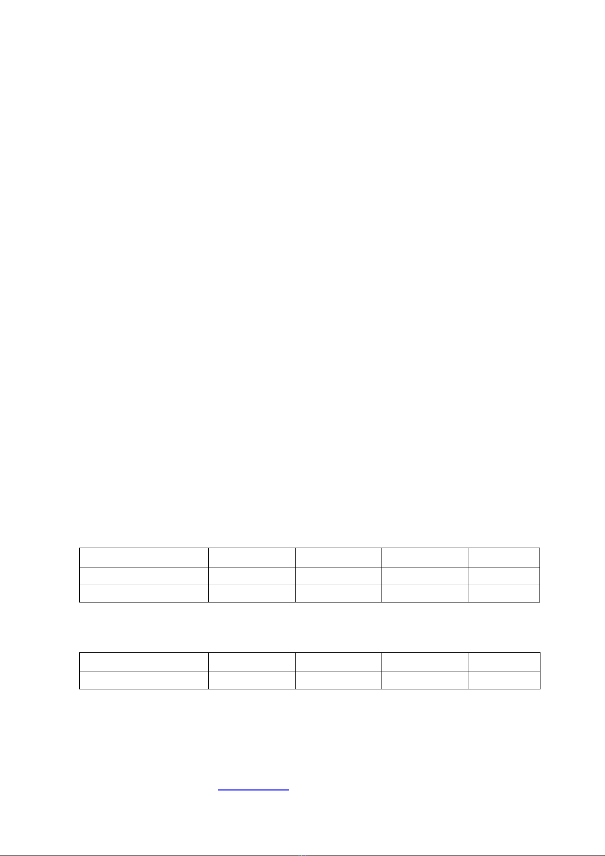
5 – OUTLINE DIMENSIONS AND WEIGHT
SIZE (kW) Width (mm) Height (mm) Depth (mm) Weight (kg)
(approximate)
5,5 – 7,5 – 11 (*1) 300 615 240 17
15 – 18,5 – 22 (*2) 300 615 260 36
(*1) For sizes 7,5 – 11kW, N°1 EXTERNAL Braking Resistor (50Ω1500W)
(*2) For sizes 15 – 18,5kW, N°2 EXTERNAL Braking Resistors (50Ω1500W)
For size 22kW, N°3 EXTERNAL Braking Resistors (50Ω1500W)
BRAKING RESISTOR
Width (mm) Height (mm) Depth (mm) Weight (kg)
(approximate)
50Ω
ΩΩ
Ω1500W
480 110 140 2
For further information and advice contact:
SMS SISTEMI e MICROSISTEMI s.r.l. (Gruppo SASSI HOLDING)
Cap. Soc. 260.000 i.v.
Via Guido Rossa, 46/48/50 40056 Crespellano BO
R.E.A 272354 CF - Reg. Imprese Bo 03190050371 P.IVA IT 00601981202
Tel. : +39 051 969037 Fax : +39 051 969303 Technical Service: +39 051 6720710
Web : www.sms.bo.it E-mail : sms@sms.bo.it